

лекции, учебные пособия / технические тексты для группы б. / Ref 1 / Engineering today / Power units
.doc|
Hybrid power units for municipal buses Prof. Dr. Techn. Sci. N. GULIA Machine Design Department Moscow State Industrial University Dipl. Eng. S. YURKOV, ZIL plant Electrochemical generators (ECG), or the fuel cells, are the sources of energy in electrobuses. The efficiency of these generators can reach 0,7. ECGs operate on hydrogen, although with a special converter they may function on conventional fuel, thus making use of the existing infrastructure of the fuel and filling-up system. Analysis of the energy characteristic of municipal buses shows that the chemical energy of fuel is utilized for movement of the vehicle only by 15% and less. Approximately the same efficiency characterizes utilization of energy in electromobiles and electrobuses, in view of loss of electric power during power transmission, in transformers and converters, in battery charging units, in batteries themselves during their charging and operation, in electric machines, including traction and generating modes, as well as in braking systems with account of frequent acceleration and deceleration. In order to use internal combustion engines (ICEs) as well as ECGs in optimum automobile modes an additional energy storage is needed. The average power utilized by a municipal bus during movement is by several factors less than the ICG power in optimum mode, close to the mode of maximum power. Therefore this power may be used only periodically and saved in a storage. The power of the storage may be spent during movement of the bus and, what is important, it can be replenished when the bus slows down. When used in an electrobus, the ECG specific power, in optimum power mode (at maximum efficiency) roughly equals to 60 Wt/kg. Therefore, when choosing the frame of the ECG battery with account of the average power of the bus engine, the specific power of the ECG proves to be insufficient for development of maximum power of the bus. Besides, when the bus slows down, it is impossible to use the kinetic energy of the bus to recharge the ECG, because ECGs are not batteries. An additional energy storage is needed that could operate not only as a recuperator of surplus energy but as an energy concentrator as well, that would be continuously charged with small energy. So, the problem that needs to be solved is in choosing an additional energy storage and selecting the method of transmitting and retrieving energy to and from this storage. Hybrid automobile power units may be equipped with ICE or with an electric energy source, predominantly the ECG. The first group is represented by the following hybrid power units: hydro-gas with hydrostatic drive; electrochemical with electromechanical drive; fly-wheel with gear-less drive. The second group is represented by the following hybrid power units: condensing with electromechanical drive; flywheel with electromechanical drive; flywheel with gear-less drive. Hydro-gas hybrid power units with hydrostatic drive Experimental buses with hydro-gas storages and hydrostatic drive were developed and tested almost at the same time by researchers in "Volvo" (Sweden), Kursk Polytechnic Institute, Lviv bus producing plant and Gomel "Gidroprivod" plant. Fig. 1 represents the scheme of a bus with an ICE, hydro-gas storages and a hydrostatic drive. The torque from the engine (1) is transferred to the driving wheels of the bus through the gear-box (2), the cardan shaft (3), a reducing gear (4) and the final drive (5). When brakes are applied, the hydraulic unit (7) connected to the bus transmission through a cardan shaft (6), starts pumping a liquid (oil) from a tank (8) through a distributor (9) into a hydro-gas storage (10), accumulating energy in condensed gas (nitrogen). At this point the bus engine is off. When the bus starts speeding up, oil from the hydro-gas storage is supplied to the hydraulic unit (7), which is working in the mode of a hydraulic engine. The final stage of acceleration is carried out with the bus engine and the hydraulic engine working simultaneously.
Fig. 1. Scheme of a bus with ICE, hydro-gas storage and hydrostatic drive According to data from "Volvo", as well as Russian companies, fuel in buses with hybrid power units of this type is saved by 30...50% as compared to municipal buses. The amount of toxic emissions in exhaust gases is reduced by a factor of 3. However, due to their limited energy capacitance hydro-gas storage units are efficient only for recuperation of kinetic energy of buses during braking. Electrochemical hybrid power units with electromechanical drive The latest hybrid power unit with an electrochemical storage and an electromechanical drive has been implemented in Toyota's "Prius" model. The scheme of the power unit of this car is presented in fig. 2. An ICE (8) of 45 kWt turns an AC generator (7) that feeds the traction AC electric engine of 30 kWt (4). Engines (4) and (8) through differential gear (6) can connect with the driving wheels. Loading of each unit is determined by a board computer (1). Special batteries (3) are used as a storage – forty cans with capacitance of 260 Ah. Even the heat of the engine is utilized – through a special heat accumulating battery it facilitates release of hydrogen from a can with nickel hydride, producing additional energy. The hybrid power unit of the above type is complex and costly, but it allows to cut fuel consumption by a factor of 2.5 and significantly reduce toxic emissions in exhaust gases.
Fig. 2. Scheme of a hybrid power unit with electrochemical storage and electromechanical drive: 1 – board computer; 2 – current converters; 3 – batteries; 4 – AC electric engine; 5 – differential gear; 6 – final drive; 7 – AC generator; 8 – ICE Flywheel hybrid power units with gear-less drive A flywheel storage is the best choice for hybrids that include an ICE, because it stores energy directly in mechanical form and does not require conversions. In this case a storing super flywheel, produced by coiling highly strong materials – wire, bands or fibre, proves to be very efficient. A super flywheel is a Russian national invention. The first patent document was issued to Dr. N.V.Gulia in May 1964 (USSR author's certificate # 1048196 was issued in 1983), i.e. earlier than the first US patent (January 1965). In 1966...67 Dr. N.V. Gulia carried out the first tests of safety of super flywheels, specifically, of the belt type. In 1966...73 Dr. N.V. Gulia designed, developed and tested special variators, called discrete variators, which allowed to transfer the torque from the flywheel to the driving wheels. Economy in fuel consumption of 45% was reached. However a discrete variator turned out to be a complex additional unit in bus transmission, therefore this solution was never implemented in practice. Later the initiative in this sphere was taken up by countries with high level of technology development – USA, Japan and Western European countries. According to information from the Livermore National Laboratory (USA), actively participating in development of hybrids for cars, specific energy capacitance of graphite super flywheels can reach 545 Wt h/kg, that by far outperforms modern sodium and sulphur batteries used, for example, by BMW, with a similar characteristic reaching 144 Wt h/kg. Of all energy storages, application of the super flywheel has the best prospects due to a favourable combinations of high specific energy capacitance and safety characteristics (no fragments in break-downs). Electric, hydrostatic and mechanical transmissions may be used for hybrid power units with ICE and flywheel. The most promising is the mechanical gear-less transmission. Notwithstanding a sufficient number of pilot models, serial production of a gear-less mechanical transmission, capable of effective transfer of mechanical energy from the flywheel to the driving wheels of a vehicle, has not been achieved. This is explained by the necessity to attain a high level of efficiency and a wide variation range of the transmitting ratio (more than 20). Therefore, such companies, as "Lockheed" (USA), "Volvo" (Sweden), "MAN" (Germany), etc. use electric or hydrostatic transmissions for hybrid power units with ICE and flywheel. There are good prospects in use of gear-less transmission based on a planetary disc variator for the mentioned hybrid. High efficiency (around 0,95) of planetary variators in high gear allows effective recuperation of kinetic energy. Fig. 3 presents a scheme of a bus with a flywheel storage and gear-less transmission. Power from ICE (1) with reduced power (around 50% of the nominal figure) is transferred through gear (2), implemented either with remote control or in the form of an electromagnetic multi-disc clutch, through a reverse mechanism (3), located in a crankcase connected to the power take-off box (4). The power flow is divided after passing the reverse mechanism. Part of the power through the planetary disc variator (5), cardan shaft (6) and final drive (8) is transferred to the driving wheels of the bus. The other part is transferred to the super fly wheel of the flywheel storage (10) through the power take-off box (4), cardan shafts (7), bevel gearing with a spiral tooth and clutch (9). The flywheel storage is fixed to the bus frame with coiled or rubber suspensions (11) with dampers to suppress gyroscope loads.
Fig. 3. Scheme of bus with flywheel storage and gear-less drive Before starting movement of the bus during several minutes the super flywheel is driven up by the ICE (1) to the nominal rotation speed of the crankshaft of 15000 min (-1). Variator (5) at this point is in neutral position. Then the gear (9) is switched off, the bus starts off and gains speed of 8...10 km/h from an ICE of small power. The super flywheel runs idle. At that moment in between the ICE and the final drive step-down gearing with transmitting ratio of 2...3 is turned on in sequence with the variator, which significantly eases starting off the bus. After this transmission (2) can be turned off, ICE is stopped, transmission (12) is switched into gear and the movement of the bus is supported by the storage, which transmits the torque through the bevel gearing (9), cardan shafts (7), power take-off box (4), reverse mechanism (3), planetary disc variator (5), cardan shaft (6) and final drive (8) to the driving wheels. When the energy supply in the storage diminishes, transmission is switched into gear (2) automatically and the ICE (1) is started. While the ICE works in optimum mode the energy in the storage increases. This allows to use a planetary disc variator with the variation range of the transmitting ratio of 6...8 in the hybrid power unit. When applying brakes, the transmitting ratio of the variator (5) smoothly increases and the speed of the bus is reduced to 8...10 km/h, when its kinetic energy is very low. Further slow down of the bus is carried out by braking mechanisms. The energy is returned to the super flywheel. Only this recuperation of energy allows to save at least 30% of fuel during exploitation of the bus in urban conditions. It should be mentioned that all systems of the described hybrid scheme – flywheel storage, system of automatic start-ups, etc., except for the variator, have been tried out on recognized models of hybrid power units with fly wheels well enough. The described system is the most simple one, inexpensive, its technology is similar to existing automotive technologies. Due to the high efficiency of the planetary variator and the fact that the system does not include conversion of mechanical energy into electrical and back and avoids losses of energy, it is very economical in operation. The control scheme is much more simple as compared to other systems, for instance, Toyota's "Prius", mentioned above. Therefore, the expected outcome in reducing fuel consumption and toxic emissions should be at least at the level of competitors. Should application of electric and hydrostatic transmissions be considered in the same function as the variator is used in fig. 3, the technical solutions in this case should not differ. The variator (5) is changed for a gear-less transmission consisting of two reversible electric or hydrostatic machines. Functions of the reversing gear are carried out by relative electric or hydro-devices. It is important that the flywheel can be joined as in fig. 3 to the gear-less transmission, to the electric or hydro-machine, which is connected to the ICE. Thus, the flywheel storage does not require any additional electric or hydro-machine. This is a significant asset in decreasing its weight and dimensions. If the drives should be compared with electrochemical or flywheel storages, only the mass and volume of the flywheel storage should be taken into consideration. The additional electric machine should be excluded, because the number of electric machines in these drives is the same. Hybrid power units with electric power sources Condensing units with electromechanical drive Introduction of additional condensing energy storages in buses should require heavy and bulky condensers. Thus, modern condensing storages applied in the automotive industry, have specific energy characteristics of 0,55 Wt h/kg and 0,8 Wt h/litre. In this case, in order to store 2 kWt h of energy (a figure, recommended by experts for hybrid power units in buses) a condenser weighing more than 3000 kg or with a volume of 2,5 m3 would be needed, which is unrealistic. As a matter of comparison, a flywheel with specific energy capacitance of 50 Wt h/kg and energy store of 2 kWt h weighs only 40 kg for a bus with full mass of 20000 kg. Besides, in case of a break-down (short circuit) the powerful condensers are apt to catch fire which is extremely dangerous in passenger transport. Flywheel units with electromechanical drive The latest systems of hybrid power units based on ECG, specifically, those developed for taxi cars in the USA, have an additional flywheel storage with an electromechanical drive. The power scheme in this case is as follows: the power source (ECG) feeds a low power flywheel storage, regularly replenishing it with energy, while a reversible electric machine, connected to the flywheel and calculated for maximum power, required by the bus, is electrically connected through a system of current conversions and controls with the traction electric engine and mechanically – with the final gear, transmitting rotation to the driving wheels. The scheme of the hybrid power unit of a car with a flywheel storage and electromechanical drive of BMW company is presented in fig. 4.
Fig. 4. Scheme of hybrid power unit with flywheel storage and electromechanical drive The power source (1) through a system of converters and control (2) is connected to the reversible electric machine (3), calculated for maximum power required by the car. The electric machine (3) through complex differential gear (7) with step-up gear (6) is joined to the flywheel of the storage and final drive (4). Thus, the operation of the hybrid power unit is carried out, including recuperation of energy. However, one drawback, persisting in all systems with power electric transmission, especially in the case of buses, is the heavy weight of the reversible traction engine (similar to the trolley-bus). Another negative aspect in this scheme is the inefficient work of the high power electric machine (3) – driving up the hand-wheel (5) does not require a lot of power. Differential gear (7), complex in terms of structure and control, equipped with step-up gear (6) alongside a reducing final drive (4) is also a shortcoming. At the same time, it must be stressed, that the one single electric machine in the scheme is an unquestionable advantage of this technical solution. The flywheel storage is additionally supplied with a reversible electric machine practically in all existing schemes with electric power sources, which significantly complicates and overloads the construction. Flywheel units with gear-less drive
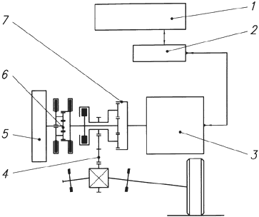
Fig. 5 presents a scheme representing a new concept of a power unit for an elctromobile, proposed by N.V. Gulia. Fig. 5. Scheme of bus with ECG, flywheel storage and gear-less drive The power source (ECG) (1) is connected to the electric engine (2). The electric engine (2) consumes a small amount of power from the ECG and transfers it to the super flywheel of the flywheel energy storage (10), thus storing mechanical energy, required for movement of the electrobus. Then, as opposed to all existing electromobile schemes, the scheme of transferring the torque into the transmission is absolutely the same as in automobiles. The torque from the super flywheel is transferred to the driving wheels through bevel gearing with clutch (9), cardan shafts (7), power take-off box (4), reversal mechanism (3), planetary disc variator (5) with supplementary gear-box, cardan shaft (6) and final drive (8). Thus, in the existing scheme of a hybrid power unit (fig. 3) an accelerating electric engine of low power fed by an ECG power source is included instead of ICE and transmission. The ECG power source with specific energy of 400 Wt h/kg and specific power of 60 Wt/kg calculated for a total run of 400 km of an elctrobus of 20000 kg will weigh about 1000 kg and produce up to 60 kWt of power at maximum efficiency. The speed accelerating electric engine of 50 kWt should weigh approximately 50 kg. The super flywheel with specific energy of 50 Wt h/kg and energy capacitance of 2 kWt will weigh 40 kg, while the storage unit should weigh 100 kg. The weight of the variators is around 150 kg. The total weight is less than 1500 kg, which is very close to the weight of the bus power unit. Thus, as far as weight and assembly characteristics are concerned, chassis of a conventional municipal bus may be used for an electrobus. As to dynamic characteristics, this electrobus will not be inferior to the bus with a 200 kWt engine. Environmental requirements will be fully observed. High efficiency of the ECG and effective recuperation of energy will guarantee consumption of fuel 3 times less than by conventional buses. In conclusion, it should be mentioned that development of the planetary disc variator for hybrid units for buses and electrobuses, is carried out primarily based on the ZIL-5301 automobile by the Moscow State Industrial University and ZIL plant with participation of the authors of this article.
|


|
Date of the publication: December 15, 2001 |