
text 01. Diesel engines
Part I. Slow-, medium- and high-speed diesel engines
A Diesel engine is a propulsion plant in which the heat that is generated by internal combustion of a mixture of fuel and air is converted into power.
There are slow-speed, medium-speed and high-speed Diesel engines. By "speed" is understood the number of revolutions per minute (RPM) the shaft can make. The slow-speed Diesel engine is applied in large vessels with large engine rooms. These engines are very reliable, but take up a lot of space.
Slow-speed Diesel engines consume Heavy Fuel Oil (HFO), which is an inexpensive fuel. This type of fuel, also called residual oil, is used in medium-speed Diesel engines, too.
These engines are favoured in large vessels, e.g. in ferries. Compared to the slow-speed engine the medium-speed engine is more compact. The medium-speed Diesel engine requires more maintenance.
High speed Diesel engines are used in small, highly manoeuvrable vessels. The rated capacity of such an engine is very high, but so is its fuel consumption.
Part II. In-line engines and V-engines
Diesel engines may have cylinders that are placed "in line" or in a bevel (oblique) position. Compared to the in-line engine the advantages of the V-engine are obvious: a V-engine requires only one crankshaft and takes up less space. Therefore the V-engine is very suited to be installed in engine rooms of limited size, contrary to the in-line engine, which cannot be used in small engine rooms due to its height. The in-line engine is not as costly as the V-engine. The construction of the in-line engine is simple, which makes the maintenance and overhauling relatively easy and cheap.
Part III. Trunk engines and Crosshead engines
As to the construction of Diesel engines we distinguish two main types: the trunk engine and the crosshead engine. In a trunk engine the piston pin and crank pin are directly connected to each other by the connecting rod. Trunk engines are of compact build and are mostly medium speed- or highspeed engines. Compared to the crosshead engines they do require more maintenance. The crosshead engine is taller because of the crosshead and piston rod, which require more space. These engines are mainly used in large vessels. The crosshead serves as a hinging connection between piston rod and connecting rod.

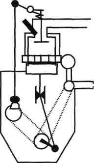
Crosshead guide shoes and crosshead guides absorb the forces onto the crosshead when the piston goes down.
With a direct-acting (or direct-reversible) crosshead engine maintenance costs can be kept to a minimum because there is no reversing gear. The crosshead engine is reputed to be very reliable, but is considered to be more costly compared to the trunk engine.
Part IV. Two-stroke engines and four-stroke engines
The piston in a cylinder makes a reciprocating motion - it goes up and down. The up and down motions of a piston are called strokes. The number of strokes of a piston that form a cycle in a cylinder is two or four. The two-stroke principle is applied in slow speed engines. Compared with the four-stroke engine, its advantage is that each cylinder is capable of generating more power, because the number of power strokes by the piston is twice as many as with the four-stroke cycle at the same crankshaft speed.
The disadvantage of the two-stroke engine is that, unlike with the four-stroke engine, its effective power is limited due to the fact that its ability to burn fuel is less than in a four-stroke engine. This latter engine is used in smaller vessels with medium-speed or high-speed engines.
Part V. The working of a two-stroke engine
The two-stroke cycle begins when the piston is in its Bottom Dead Centre (BDC).
Air enters the cylinder through the inlet ports. During the compression stroke the air in the cylinder is compressed while the piston travels upwards. Fuel is admitted to the cylinder at the end of this stroke. The mixture of air and fuel ignites spontaneously due to the high compression and consequent high temperature in the cylinder. During the power stroke the piston is pushed down by the "explosion" of the mixture in the cylinder.
The reciprocating piston and connecting rod will cause the crankshaft to rotate. Now the camshaft is actuated, so that the rocking lever can open the valve (a pushrod may be inserted as a distance piece between camshaft and rocking lever).
Thus, at the end of the power stroke, the exhaust valves are opened, allowing the exhaust gases to escape into the exhaust gas manifold, after which the remaining exhaust gases are removed out of the cylinder by scavenging air. The scavenging system that is most widely employed nowadays is the uniflow scavenging system, because it removes almost all the exhaust gases out of the cylinder. Cross scavenging – or loop scavenging systems are not effective enough and will leave behind small amounts of gases that will form carbon deposits in the cylinder. Before a new cycle is started, the exhaust valve is closed by the exhaust valve spring or by a hydraulic system.
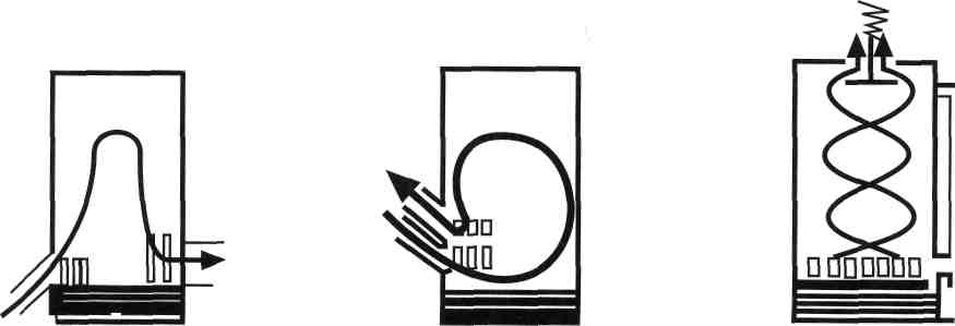
Cross scavenging Loop scavenging Uniflow scavenging
Part VI. The working of a four-stroke engine
Four-stroke engines are usually medium speed or high-speed engines.
The four-stroke cycle begins when the piston is in its Top Dead Centre (TDC).
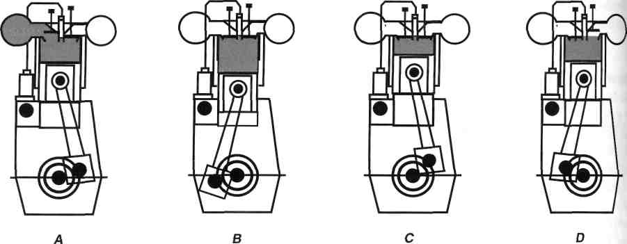
During the inlet stroke (also called suction stroke or air-induction stroke) the inlet valve is opened and air is drawn into the cylinder (A).
During the compression stroke, when the piston has just passed its Bottom Dead Centre (BDC), the inlet valve is closed and the air in the cylinder is compressed by the piston going up (B).
At the end of this stroke the fuel is injected by the atomizer. The nozzle on the atomizer divides the fuel into very small particles, so that it can mix with the air in the cylinder.
During the power stroke the mixture of air and fuel is burnt by the high temperature in the cylinder The "explosion" that follows will move the piston down (C). The reciprocating piston and connecting rod will cause the crankshaft to start rotating, which will actuate the camshaft. Now the rocking lever will actuate the valve mechanism.
In the four-stroke cycle the exhaust gases in the cylinder are removed by the piston itself. During this exhaust stroke the exhaust valve is opened, allowing the exhaust gases to escape from the cylinder (D).
Part VII. The valve mechanism
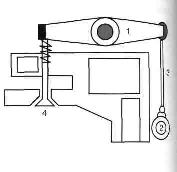
Part VIII. Reversing the engine. Controllable pitch propellers.
The slow speed Diesel engine is mostly a direct reversible - or direct acting - engine.
This means that the shaft is directly connected to the engine. In order to go from ahead to astern – or astern to ahead - we must stop the engine first and then reverse it. With a reversing gear the engine can be reversed without having to stop the engine first. It is used in small vessels. Vessels that require to be highly manoeuvrable, with variable rated capacities, are equipped with controllable pitch propellers.
By pitch is understood the distance travelled after one revolution of the propeller, but it also indicates the blade-angle of the propeller.
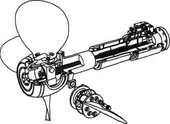
A Controllable Pitch Propeller, or C.P.P, is fitted with adjustable blades. These blades can be put in various positions, whereby the angle of the blades determines the speed at which the vessel will proceed.
In other words: the propeller-pitch can be controlled by adjusting the blades. The blades can even be put in such a position that the sailing direction can be altered from ahead to astern.
The advantage of the C.P.P. is that the number of revolutions per minute (RPM) will remain constant, in spite of an increase or reduction of sailing-speed.
The engine will have a longer life, because it does not suffer from extensive wear that is normally caused by a constantly changing RPM.
The Shaft
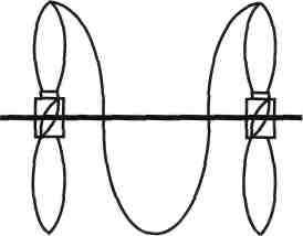
The shaft consists of the propeller shaft, the intermediate shaft and the crankshaft. They are connected to each other by means of flanges.
The end of the propeller shaft is conical (tapered) to make it easier to mount the propeller. The intermediate shaft is a distance piece between the crank shaft and the propeller shaft. Bearing-blocks and thrust blocks support the shaft. Thrust blocks take up the propulsion forces of the screw and convey them to the hull of the ship.
Diesel Engines: tasks
1) Idioms
The italicized words in the text are given below in alphabetical order. Find out what they mean as they appear in the text and learn them by heart.
actuate |
compression stroke |
direct acting |
adjustable blades |
connect |
direct reversible |
admit |
connecting rod |
disadvantage |
advantage |
consume |
distance travelled |
air induction stroke |
control |
distance piece |
alter |
Controllable Pitch Propeller |
distinguish |
angle |
convey |
effective power |
apply |
crank |
employ |
atomizer |
crankshaft |
equipped with |
bevel |
crankweb |
exhaust valve |
Bottom Dead Centre |
cross scavenging |
exhaust gases |
campeak |
crosshead engine |
flange |
camshaft |
cylinder |
fuel consumption |
chain |
decrease |
gearwheel |
compression |
determine |
generate |
ignite |
power stroke |
rotary motion |
increase |
power |
sailing direction |
insert |
propulsion plant |
scavenging |
internal combustion |
pushrod |
shaft |
limited |
rated capacity |
spontaneously |
loop scavenging |
reciprocating motion |
spring |
maintenance |
reduce |
stroke |
manifold |
reliable |
suction |
mixture |
remain |
thus |
nozzle |
remove |
Top Dead Centre |
oblique |
reverse |
uniflow scavenging |
overhaul |
reversing gear |
valve |
pin |
revolution |
valve seat |
piston |
rocker arm |
|
piston rod |
rocking lever |
|
