

Shader Debugging
Now that we have discussed the details of implementing shaders, let's talk about debugging. Determining what a shader is doing when it has gone astray is much easier when using a tool. Graphics chip IHV nVidia has provided a shader debugging tool on their web site (see http://www.nvidia.comon the developer area). I have marked the views provided by the nVidia shader debugger, shown below in Figure 6, so you can quickly locate where the shader details are presented.
First and foremost is the "Current Program" view. This contains our shader program and allows us to step through the instructions. The current instruction is displayed in blue, along with a dash symbol ("-") on the left. Any program lines with breakpoints set will have an asterisk ("*") along side them. The program display shows a disassembly of the currently set instruction; note it may look quite different to the source file originally used to compile the shader (particularly in terms of how register swizzle/masks are displayed). All programs finish with a "-end-" indicator to show that the shader is finished. Above the program display, in the column title, the current handle of the active shader is displayed. This matches the handle that the API returns as the result of aIDirect3DDevice8::CreateVertexShadercall.
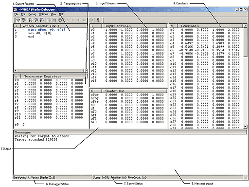
Figure 5. nVidia shader debugger
Other important views include:
"Temp Registers" view, which allows us to view intermediate results as we step through the program.
"Input Streams" view, which allows us to see our original source data, as does the "Constant" view for any constants we loaded.
"Shader Output" view, which is where you will see a numerical representation of the shader output.
Finally, the bottom of the shader shows us debugger status, scene status, and a message output view.

Figure 6. nVidia shader debugger toolbar, with relevant commands shown
The debugger can be driven from the menu or from the toolbar. All options available in the menus can be accessed from the buttons on the toolbar. It is often most convenient to use the toolbar. The toolbar contains icons for the available debugger commands, and the ones relevant to vertex shaders are shown in Figure 6.
See nVidia's documentation for full details on using these buttons and this valuable tool. This is one extremely useful tool and if you are going to be doing any hard-core shader development, I highly suggest downloading this tool and getting familiar with it. Note this cool tool also allows you to perform pixel shader debugging, but that's a future column.
Some Simple Shaders for Your Viewing Pleasure
We've covered the APIs to use shaders, vertex definitions, shader declarations, shader definitions, and the nVidia shader debugger. Now it's time to see our vertex shaders in action. The BaseVS sample starts up using the FF pipeline. Hitting the 'v' key enables vertex shaders. You can then choose a shader from the Vertex Shader menu.
The first vertex shader, SimpleVertexShader0, performs the basic transform and uses a constant color. Looking at the code again, below:
vs.1.0 // Shader version 1.0
m4x4 oPos , v0 , c4 // emit projected position
mov oD0 , c8 // Diffuse color = c8
This vertex shader uses the m4x44x4 matrix transform instruction to take a combined world*view*projection matrix and transform the vertex position by that matrix and place the resulting transformed position (a vector) in theoPosoutput register. Then a constant diffuse color is loaded into theoD0color output register. Note this shader depends on us loading a combined world*view*projection matrix as a constant. We did that using utility routine as follows:
LoadMatrix4( m_pd3dDevice , 4 , m_matWorld * m_matView * m_matProj );
The body of LoadMatrix4 is show below:
void LoadMatrix4( IDirect3DDevice8* pdevice , DWORD creg , const D3DXMATRIX& matrix )
{
D3DXMATRIX trans;
D3DXMatrixTranspose( &trans , &matrix );
pdevice->SetVertexShaderConstant( creg , &trans , 4 );
}
Note it loads the transpose of the original matrix, and uses IDirect3DDevice8::SetVertexShaderConstant to load the matrix into a constant register. In addition, a constant color was loaded inc8due to our invoking:
float color[4] = {0,1,0,0};
m_pd3dDevice->SetVertexShaderConstant( 8 , color , 1 );
It can't get much simpler than that. Figure 7 shows the result of this simple vertex shader.
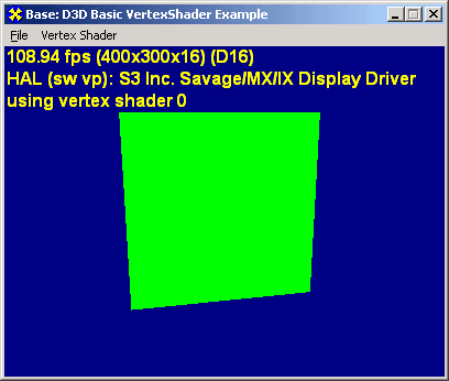
Figure 7. Constant-color vertex shader
I suggest you use the nVidia shader debugger to step through this shader if anything is unclear. Hint, Figure 5 shows using the shader debugger on this shader.
The second shader, SimpleVertexShader1, produces almost the same result, but does so in a slightly different fashion. Looking at the code forSimpleVertexShader1 below:
vs.1.0 // Shader version 1.0
dp4 oPos.x , v0 , c4 // emit projected x position
dp4 oPos.y , v0 , c5 // emit projected y position
dp4 oPos.z , v0 , c6 // emit projected z position
dp4 oPos.w , v0 , c7 // emit projected w position
mov oD0 , v5 // Diffuse color = vertex color;
We see that instead of combining the operation on each vertex component into one operation using the m4x44x4 matrix transform instruction, this shader operates on each vertex component using thedp44x1 vector transform instruction. This is exactly equivalent, and if you remember from last month's column, them4x4instruction was shown to expand to 4 slots/clocks. The above fourdp4instructions are exactly whatm4x4expands to. No mystery now! Note the vertex position is in input registerv0, and the diffuse color is in input registerv5just like our shader declaration stated. Also note that some standard constants are preloaded in constant registersc0-c3by way of the shader constant declaration line:
D3DVSD_CONST(0,1),*(DWORD*)&c[0],*(DWORD*)&c[1],*(DWORD*)&c[2],*(DWORD*)&c[3],
In addition, the transform is again loaded in constant registers c4-c7, due to our invoking:
LoadMatrix4( m_pd3dDevice , 4 , m_matWorld * m_matView * m_matProj );
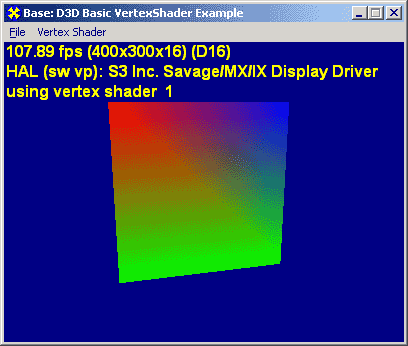
Figure 8. Diffuse-color vertex shader
Here the color stored in the input stream register is favored over the one loaded in the constant register that was used in the previous shader. See Figure 8 for an example of a simple diffuse color vertex shader.
The third shader, SimpleVertexShader2, adds texturing to our vertex shader bag of tricks. Looking at the code forSimpleVertexShader2 below:
vs.1.0 // Shader version 1.0
dp4 oPos.x , v0 , c4 // emit projected x position
dp4 oPos.y , v0 , c5 // emit projected y position
dp4 oPos.z , v0 , c6 // emit projected z position
dp4 oPos.w , v0 , c7 // emit projected w position
mov oT0.xy , v7 // copy texcoords;
The same constant registers are loaded as we saw for SimpleVertexShader1. The input stream bindings are the same with the addition of texture coordinates bound to input registerv7. We see that this shader also operates on each vertex component using thedp44x1 vector transform instruction. Then this shader moves texture coordinates from input registerv7to output registeroT0. That produces the textured output seen in Figure 9.
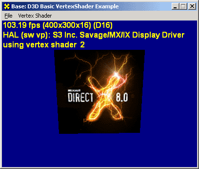
Figure 9. Simple texturing vertex shader
The fourth shader, SimpleVertexShader3, adds lighting to our vertex shader bag of tricks. Looking at the code forSimpleVertexShader3 below:
vs.1.0 // Shader version 1.0
dp4 oPos.x , v0 , c4 // emit projected x position
dp4 oPos.y , v0 , c5 // emit projected y position
dp4 oPos.z , v0 , c6 // emit projected z position
dp4 oPos.w , v0 , c7 // emit projected w position
dp3 r0 , v3 , c12 // N dot L in world space
mul oD0 , r0.x , v5 // Calculate color
mov oT0.xy , v7 // copy texcoords
We see that this shader also operates on each vertex component using the dp4 4x1 vector transform instruction. Then this shader performs the classic N dot L lighting operation using the dp3 vector transform instruction on the normal component in register v3. If the result of this operation is less than zero, the polygon is not facing the light and hence, not visible. We use that fact when calculating the result color using the mul operator into the output register oD0. Here we rely on the post-shader clamping of values to the range [0,1]; technically that calculation is part of the lighting phase, but why do it twice? Finally, the texture coordinates are updated into output register oT0 from register v7. One other detail, we have to change the texture stage operator to modulate so that we get the diffuse and texture combined as the resulting output color. This results in the "quad" as shown in Figure 10.

Figure 10. Simple lighting and texturing vertex shader
Note that in addition to the texture being modulated by the diffuse color, the "quad" shows all black on the back-face as it rotates away from the light which is visually correct in that the back-face has no lighting and should be solid black.
That concludes our coverage of simple vertex shaders. We've just started to scratch the surface. Other uses for vertex shaders include character animation, custom fog effects, and wacky lighting effects. The fact that you write the shader code and are not dependent on the functionality provided by the fixed function pipeline really does give developers freedom and control. I encourage you to take this code and the nVidia shader debugger tool and continue to experiment on your own.