

Определение на фотографиях контуров лица и подбородка / !!!IMPROVED CHIN FITTING ALGORITHM BASED ON AN ADAPTIVE SNAKE
.pdfIMPROVED CHIN FITTING ALGORITHM BASED ON AN ADAPTIVE SNAKE
Paul Kuo, John Hannah
Institute for Digital Communications, Joint Research Institute for Signal & Image Processing School of Engineering and Electronics, University of Edinburgh, King's Buildings Edinburgh, UK, EH9 3JL. Email: P.P.Kuo@ed.ac.uk
ABSTRACT
Fitting of the chin is an essential part of facial model tting systems. Many previous approaches to chin tting have used active contour models or snakes. However, achieving successful chin tting for a wide range of faces under varying lighting conditions has not proved straightforward. This paper describes an approach to chin tting based on active contour models which is capable of operating successfully under unbalanced lighting conditions and for a wide range of faces. The system uses a fast adaptive algorithm which adjusts the snake parameters according to image characteristics. Results are presented for chin tting on a large database of faces.
Index Terms— Image processing, Object recognition, Image edge analysis,
1. INTRODUCTION
Fitting the chin is a major requirement for face modelling and facial expression analysis. Traditional chin tting exploits dynamic curve tting techniques such as Active Contour Models (Snakes) and Deformable Templates. Kampmann [1] used a deformable template using four parabolas arguing that this was more accurate than a single parabola but only showed results for a limited range of face images. Hu et al [2] proposed a combined scheme of deformable templates and an active contour model. The chin contour was initially tted by a parabola then re ned by gradient vector ow snake. Sun et al [3] also used an active contour model to t non-parabola- like chins. A `shape reference' was trained using example faces and used to constrain their snake evolution. Wang et al [4] developed a scheme to extract and classify chins as round, pointed or trapezoidal using intensity and edge properties. They claimed fairly high rates of success for extraction and classi cation on a large data set.
Our new tting algorithm is also based on an active contour model approach but introduces a number of valuable new features. It can operate under non-uniform illumination by using different chin tting schemes depending on lighting conditions. It greatly reduces computational effort by using a 1D (one dimensional) `radial' active contour. Automatic adjustment of the snake parameters based on the characteristics of
the image allows chin tting in a wide range of faces.
2. OVERVIEW OF APPROACH
Figure 1 shows the overall block diagram of our chin tting system. A chin search region is derived from lip corner points (as located by [5]) and face boundary points (obtained by skin detection as in [6]). If an illumination analysis shows the face is frontal-lit, an active contour model is used to extract the entire chin. If it is side-lit, only the chin contour on the brighter side is tted. Facial symmetry is used to extrapolate this contour to the darker side to initialise a second snake. The entire chin is tted by combining results from both sides.
Locations of Lip corners |
|
|
|
|
|
|
|
|
|
|
|
|
|
|
||
from Lip Extraction |
|
|
|
|
|
|
|
|
|
Determining |
||||||
|
|
|
|
|
|
Defining the chin |
|
|
|
|
if the illumination |
|
|
|||
Skin Detection |
|
|
|
search region |
|
|
|
|
is frontal? |
|
||||||
|
|
|
|
|
|
|
|
|
|
|
|
|
|
|||
(locating jaw and chin points |
|
|
|
|
|
|
||||||||||
in region A1 & A2) |
|
|
|
|
|
|
|
|
|
|
|
|
|
|
||
|
|
|
|
|
|
|
|
|
|
|
|
|
|
|
|
|
|
|
Yes |
|
|
|
|
|
|
|
|
|
|
|
|
|
|
|
|
|
|
|
|
No |
|
|
|
|
|
|
||||
|
|
|
|
|
|
|
|
|
|
|
|
|
||||
|
|
|
|
|
|
|
|
|
|
|
|
|
|
|
|
|
|
Setting up Adaptive |
|
|
Detecting the direction |
|
|
|
|
Setting up Adaptive |
|
||||||
|
Active Contour Model |
|
|
of the light |
|
|
|
|
Active Contour Model |
|
||||||
|
|
|
|
|
|
|
|
|
|
|
|
|
|
|
|
|
|
|
|
|
|
|
|
|
|
|
|
|
|
|
|
|
|
|
Chin fitting by Adaptive |
|
|
Extrapolating the second |
|
|
|
Bright half of the chin fitted by |
||||||||
|
|
|
|
|
half of the chin |
|
|
|
||||||||
Active Contour Model |
|
|
|
|
|
Adaptive Active Contour Model |
||||||||||
|
|
by symmetrical property |
|
|
|
|||||||||||
|
|
|
|
|
|
|
|
|||||||||
|
|
|
|
|
|
|
|
|
|
|
|
|
|
|||
|
|
|
|
|
|
|
|
|
|
|
|
|||||
|
|
|
Second half chin fitting by |
|
|
Complete chin fitting by |
||||||||||
|
|
|
Second Active Contour Model |
|
|
joining the result of two snakes |
||||||||||
|
|
|
|
|
|
|
|
|
|
|
|
|
|
|
|
|
Fig. 1. Flowchart shows the processing steps of our system
3. CHIN CHARACTERISTICS ANALYSIS
Figure 2 shows a frontal face image (from the XM2VTSDB database [7]). The chin contour of a face comprises two types of regions. In regions A1 and A2, the chin contour is virtually the face boundary which is usually not too dif cult to detect. In region B the contour is much less distinct since the face and neck possess very similar skin colour. Figure 3 shows the
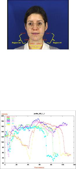
Fig. 2. Frontal image showing chin contour regions
pixel intensity pro les for the six equally spaced radial lines in Figure 2. By studying these radial intensity pro les for a range of images, the characteristics of a chin can be identi ed. In regions A1 and A2 an abrupt `fall' or dramatic change occurs when moving from skin to non-skin (e.g. lines 1 & 6 Figure 3). In region B the chin contour shows up as a (more gradual) intensity valley (e.g. in lines 2-5 Figure 3). The left hand ends of these intensity pro les are quite jagged due to the lips but need not be considered further.
Fig. 3. Intensity pro les of radial lines in Figure 2
4. DEFINING THE CHIN SEARCH REGION
The `jaw points' can be located by a line though the mouth centre (e.g. lines 1 & 6 Figure 3). Only limited head rotation is assumed. The chin search region is then de ned as the area between two concentric 180-degree arcs (centred at the mouth centre) and the face boundary. The diameter of the outer arc is set to be 1.2 times the width between the jaw points while the diameter of the inner arc is set to be 1.2 times the lip (corners) width.
5. ILLUMINATION ANALYSIS
In real world head-and-shoulders images, balanced frontal illumination may not always occur. Subjects will commonly
be lit from above the head but one side may be brighter than the other. A shadow is thus formed on the lower part of the poorer-lit side of the face. This makes chin location significantly more dif cult in this area. A simple technique to detect if the light is unbalanced and a shadow formed is required. A rectangular area is selected below the mouth centre, with length equal to the jaw width and height equal to twice the nose-mouth centres distance. This area is then divided into left and right regions and the average intensity of each is computed. One side being more than 1.5 times brighter than the other or the brightness difference being greater than 50 (grayscale 0-255) is taken to indicate unbalanced lighting.
6. CHIN FITTING IN FRONTAL-LIT FACE IMAGES
An active contour model (snake) is set up to extract the entire chin. The snake as rst proposed by Kass et al [8] is a parametric curve which is in uenced by its internal and external `forces'. The balance of the forces makes the snake converge to salient features (such as edges or intensity valleys) in the image. We use an in ating balloon snake [9] as the initialisation can be reasonably far away from the target feature.
The snake is automatically initialised to the inner arc (as de ned in Section 4) and expands towards the outer arc. This guarantees that the snake grows within the fairly homogeneous skin region. Thus the chin contour is the only feature that needs to be modelled in the snake equations.
Our active contour contains 19 control points at 10 degrees apart. This number of control points was selected based on experimental results. Our active contour only allows the control points to move radially. This 1-D movement of the control points reduces computational time greatly compared to a 2-D snake. In addition, a semicircular shape constraint is introduced, as the internal force is minimised when all the control points are an equal distance from the origin (mouth centre).
The energy equation associated with a snake v(s) is normally expressed as:
|
1 |
0 |
|
2 |
|
00 |
|
2 |
|
|||
E = |
|
|
|
jv |
(s)j |
|
+ |
|
jv |
(s)j |
|
+ Eimage + Epressureds |
0 |
|
2 |
|
2 |
|
|||||||
|
|
|
|
|
|
|
|
|
|
|
|
(1) |
The rst two terms denote the energy of the regularity of the snake. In our polar co-ordinate system, v(s) = (r(s); (s)), s 2 [0; 1]. Where r(s) is the distance from the mouth centre and (s) is the angle of inclination. The third term is the en-
ergy associated with the external force (Fimage) derived from the image. The last term is the energy associated with the
pressure force (Fpressure).
The external force is formulated based on the chin characteristic found in Section 3 and is capable of pushing the control points to an intensity valley. This force is given by:
Fimage(v(s)) = (r; ) |
dI |
(v(s)) |
(2) |
|
dr |
||||
|
|
|
The image intensity gradient term dIdr is evaluated at point v(s) on the snake along the corresponding radial line. The force is an expanding one when the image intensity gradient is negative and a shrinking one otherwise. (r; ) is a weighting factor whose value is dependent upon the image topology, so an algorithm allowing automated-adjustment is proposed in Section 6.1.
The pressure force (Fpressure) is simply a constant in ating force to make the snake progress towards the chin. A
value of 0:5 min ( min is discussed in Section 6.1) is used. The best t of the snake to the chin is found by minimising the total energy of Equation 1 after a number of iterations. Axed number of iterations (500) was used in our experiments but convergence could have been detected by setting a change threshold.
6.1. Adaptive Snake
Unfortunately, the intensity valley associated with the chin contour varies from face to face. In addition, some face images contain more `feature noise' and `unwanted edges' than others. To attempt to compensate for such variations, a topologically adaptive snake, inspired by Li et. al [10], was developed. Our snake outperforms their algorithm by using an automatically generated statistical model of image intensity to adjust the weighting factor (r; ) (Equation 2).
The pixels on a radial line within the search region are collected and the mean intensity ( I ) and standard deviation ( I ) are calculated. (r; ) is then implemented as:
(r; ) = w1( I ) w2(I I ) min |
(3) |
Where w1( I ) has the value 2 when I is zero, reducing linearly to 1 when I is > 20. This gives a larger for a homogeneous skin region (low I ) to emphasise the chin contour valley and a smaller as the `feature noise' level ( I ) increases, in order to avoid the snake being trapped at an undesired `noise' concavity. w2(I I ) has the value 2 when (I I ) is < 2 I , again decreasing linearly to 1 when I = I to encourage the snake to converge to a 'dark' valley but avoid instability. A larger is used when the image intensity at the control point is much lower than the mean I but w2 and therefore is set to zero if the intensity is higher than the mean. (The intensity valley of the chin contour is assumed to be below the mean intensity of the facial skin.)
Thus (r; ) has an overall dynamic range of 4 min. Themin (typically 0.02) was determined by extracting the chins
from several very `noisy' facial images.
7.CHIN FITTING IN SIDE-LIT FACE IMAGES
7.1.Chin Contour Extrapolation
If the facial illumination is unbalanced a balloon snake initialised as before cannot be used. This is because the additional shadow and spurious edges on the darker side of the
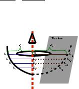
face will interfere with the progress of the snake. To avoid this we have to initialise the snake at a position which is much closer to the chin contour. Since the brighter side of the face can be identi ed as described in Section 5, the previous t- ting technique can be applied to extract the chin contour on this side. Initialisation of the snake on the darker side of the chin can then be performed by extrapolation using the symmetrical property of the face.
A line through the mouth centre (and centred between the eyes) is used as a reference as shown in Figure 4. Since the jaw points (S0 and Sn 1) on both sides of the face have been found previously, the chin on the shadow side of the face (Sn 2, Sn 3...) can be extrapolated by using the ratio of the distance of the two jaw points from the reference line. That
is, JL : JR = S1C1 : Sn 2C1= S2C2 : Sn 3C2 and so on in Figure 4. This xed-ratio extrapolation can handle cases of
moderate 3-D head rotation.
Fig. 4. Snake initialisation for the shadowed chin
7.2. Chin tting
A second snake using this extrapolated contour as its initialisation is employed to re ne the chin tting on the darker side. As the snake initialisation is now very close to the chin, an external force alone is suf cient and no pressure force is required. The external force is modi ed because the intensity valley previously used is no longer present. Instead, due to the structure of the protruding chin bone, the chin contour often shows a rapid intensity change in the shadow. This can be a re ection on the chin bone or just because the higher curvature of the chin makes the brightness change more quickly. In addition, the control points of the second snake are only allowed to move within a few pixels from their initial position.
8. RESULTS OF CHIN FITTING
Our tting algorithm achieves fairly high success rates (around 94% for frontal and side lit images, excluding beards) in our main test database (XM2VTSDB [7]). In addition, frames from Susie and Akiyo sequences were used to further test our unbalanced lighting chin tting. Figures 5(a)- 5(f) show the chin tting in frontal-lit images while tting to unbalanced lit images is shown in Figure 5(g)-5(u). Failures are mainly
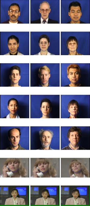
(a) subject 02511 |
(b) subject 03321 |
(c) subject 02711 |
(d) subject 02321 |
(e) subject 00511 |
(f) subject 03411 |
(g) subject 000 |
(h) subject 001 |
(i) subject 027 |
(j) subject 036 |
(k) subject 005 |
(l) subject 034 |
(m) subject 009 |
(n) subject 045 |
(o) subject 042 |
(p) |
(q) |
(r) |
(s) |
(t) |
(u) |
Fig. 5. Some results of the chin tting
due to beards Figure 5(n) and a `soft' chin (hardly discernible visually). (Figure 5(o))
9. CONCLUSIONS AND FUTURE WORK
We have reported an improved chin tting algorithm based on an adaptive snake. The adaptability allows the snake to auto-adjust its weighting factors according to the image topology so that it can t chins in a wide range of face images. For unbalanced-lit face images, the chin in the shadow is extrapolated by using the symmetrical property of the face and re ned by a second snake. Successful chin tting has been
demonstrated on a wide range of face images.
Future work will focus on tting chins with other shadow types, partially occluded chins and dealing with larger head rotation. Further improved chin tting will be used to enhance the accuracy of our wire-frame face modelling system. This will lead to more realistic expression synthesis and facial animation.
10.REFERENCES
[1]M Kampmann, “Automatic 3-d face model adaptation for model-based coding of videophone sequences,” Trans IEEE Circuits and Systems for Video Technology, vol. 12, no. 3, pp. 172–182, (2002).
[2]M. Hu, S. Worrall, A. H. Sadka, and A. M.Kondoz, “A fast and ef cient chin detection method for 2-d scalable face model design,” in Visual Information Engineering. IEE, 2003, pp. 121–124.
[3]D. Sun and L. Wu, “Face boundary extraction by statistical constraint active contour model,” in Proceedings of International Conference on Neural Networks and Signal Processing. IEEE, Dec 2003, vol. 2, pp. 14–17.
[4]J. Y. Wang and G. D. Su, “The research of chin contour in fronto-parallel images,” in Proc Second International Conference on Machine Learning and Cybernetics, Xi'an, 2003, IEEE, pp. 2814–2819.
[5]P. Kuo, P. Hillman, and J.M. Hannah, “Improved lip tting and tracking for model-based multimedia and coding,” in Visual Information Engineering. IEE, 2005, pp. 251–258.
[6]P. Hillman, J. M. Hannah, and P. M. Grant, “Global tting of a facial model to facial features for model-based video coding,” in Proceedings, 3rd International symposium on Image and Signal Processing and Analysis (ISPA03), (2003), vol. 1, pp. 359–364.
[7]K. Messer, J. Matas, J. Kittler, and K. Jonsson, “Xm2vtsdb: The extended m2vts database,” Audio and Video-based Biometric Person Authentication (AVBPA1999), (1999).
[8]M. Kass, A. Witkin, and D. Terzopoulos, “Snakes:active contour models,” International Journal of Computer Vision, vol. 1, no. 4, pp. 321–331, (1987).
[9] L.D. Cohen, “On active contour models and balloons,”
CVGIP: Image Understanding, vol. 53, no. 2, pp. 211–218, (1991).
[10]X. B. Li and J. K. Wang, “Adaptive ballon models,” in Proceedings of International Conference on Computer Vision and Pattern Recognition (CVPR). IEEE, June 1999, vol. 2, pp. 434– 439.