

7 семестр (Бормотов А) / 1man_bw_l23_30_chn_23_30_instruktsiya_po_ekspluatatsii_1 / MAN-BW L23-30 H Vol-1 (Instruction)+
.pdf51530-01H |
|
|
Lubricating Oil Separator |
|
Plate |
|||||||||
|
|
|
Page 2 (2) |
|||||||||||
L23/30H |
|
|
|
|
|
|
|
|
|
|
|
|
||
|
|
|
|
|
|
|
|
|
|
|
|
|||
|
Item |
|
|
|
|
|
Item |
|
|
|
|
|
|
|
|
|
|
|
|
|
|
|
|
||||||
|
No. |
Qty. |
|
Designation |
Benævnelse |
|
No. |
|
Qty. |
|
Designation |
Benævnelse |
||
|
|
|
|
|
|
|
|
|
|
|
|
|
|
|
016 |
1/F |
|
Flange |
Flange |
|
|
|
|
|
|
|
|
|
|
028 |
1/F |
|
Pipe with |
Rør med |
|
|
|
|
|
|
|
|
|
|
|
|
|
|
flange |
flange |
|
|
|
|
|
|
|
|
|
041 |
1/F |
|
Breather with |
Ånderør med |
|
|
|
|
|
|
|
|
|
|
|
|
|
|
flange |
flange |
|
|
|
|
|
|
|
|
|
053 |
1/F |
|
Gasket |
Pakning |
|
|
|
|
|
|
|
|
|
|
065 |
4/F |
|
Screw |
Skrue |
|
|
|
|
|
|
|
|
|
|
077 |
8/F |
|
Screw |
Skrue |
|
|
|
|
|
|
|
|
|
|
089 |
1/F |
|
Cover |
Dæksel |
|
|
|
|
|
|
|
|
|
|
090 |
1/F |
|
Gasket |
Pakning |
|
|
|
|
|
|
|
|
|
|
100 |
1/F |
|
Insert for oil |
Indsats for |
|
|
|
|
|
|
|
|
|
|
|
|
|
|
separator |
olieudskiller |
|
|
|
|
|
|
|
|
|
112 |
1/F |
|
Housing for |
Hus for |
|
|
|
|
|
|
|
|
|
|
|
|
|
|
oil separator |
olieudskiller |
|
|
|
|
|
|
|
|
|
124 |
4/F |
|
Screw |
Skrue |
|
|
|
|
|
|
|
|
|
|
136 |
1/F |
|
Gasket |
Pakning |
|
|
|
|
|
|
|
|
|
|
148 |
1/F |
|
Bend |
Bøjning |
|
|
|
|
|
|
|
|
|
|
161 |
4/F |
|
Nut |
Møtrik |
|
|
|
|
|
|
|
|
|
|
173 |
1/F |
|
Oil trap |
Olielås |
|
|
|
|
|
|
|
|
|
|
185 |
1/F |
|
Union |
Forskruning |
|
|
|
|
|
|
|
|
|
|
197 |
1/F |
|
Gasket |
Pakning |
|
|
|
|
|
|
|
|
|
|
207 |
1/F |
|
Union |
Forskruning |
|
|
|
|
|
|
|
|
|
|
219 |
4/F |
|
Screw |
Skrue |
|
|
|
|
|
|
|
|
|
|
220 |
1/E |
|
Oil separator, com- |
Olieseparator, komplet |
|
|
|
|
|
|
|
|
|
|
|
|
|
|
plete, incl item 077, |
inkl. item 077, 089, |
|
|
|
|
|
|
|
|
|
|
|
|
|
089, 090, 100, and |
090, 100 og 112 |
|
|
|
|
|
|
|
|
|
|
|
|
|
112 |
|
|
|
|
|
|
|
|
|
|
232 |
1/F |
|
Gasket |
Pakning |
|
|
|
|
|
|
|
|
|
|
|
|
|
|
|
|
|
|
|
|
|
|
|
|
|
When ordering spare parts, see also page 500.50. |
Ved bestilling af reservedele, se også side 500.50. |
||||
* |
= Only available as part of a spare parts kit. |
* |
= |
Kun tilgængelig som en del af et reservedelssæt. |
|
Qty./E |
= |
Qty./Engine |
Antal/E = |
Antal/Motor |
|
Qty./F |
= |
Qty./Filter |
Antal/F = |
Antal/Filter |
|
08028-0D/H5250/94.08.12
94.24 - ES0S-L

Index
Page1(l)
Description
Cooling Water System |
516 |
Cooling Water System............................................................................................................... |
|
516.01.(01H) |
|
Cooling Water |
Thermostatic |
Valve....................................................................................... |
516.04.(01H) |
Cooling Water |
System................................................................................................................... |
|
L23H-03XT3 |
Working Card |
|
|
|
Check of Cooling Water System....................................................................................... |
516-01.90.(01H) |
||
Cooling Water..Thermostatic Vale.................................................................................... |
516.04-00.(01H) |
||
Plates |
|
|
|
Cooling Water..Thermostatic.. |
Vale......................................................................................... |
51604-01HZ |
|
High Temperature..Fresh..Water..Pump................................................................................. |
51610-01H |
||
Pipes on..Cylinder..Head............................................................................................................. |
|
51625-01H |
|

Description |
|
Cooling Water System |
516.01 |
Page 1 (1) |
|
Edition 01H |
|
|
|
|
|
|
|
|
|
|
|
|
L23/30H |
|
|
|
V28/32S |
Description |
High Temperature Circuit |
|
|
The cooling water system consists of two separate systems. The low temperature (LT) and the high temperature (HT) circuits.
Low Temperature Circuit
The low temperature circuit is used for cooling of the charge air and the lubricating oil, and the alternator if the latter is water cooled.
The high temperature circuit is used for cooling of the cylinder units.
Cooling water is led through a distributing pipe to the bottom of the cooling water space between the liner and the frame of each cylinder unit. The water is led out through bores in the top of the frame via the cooling water guide jacket to the bore.
96.03 - ES0U-G

Description |
Cooling Water Thermostatic Valve |
516.04 |
Page 1 (1) |
Edition 01H |
|
|
|
|
|
|
|
Thermostatic Valve
The thermostatic valve in the high temperature circuit is mainly located imediately after the outlet of the engine, but alternatively in the external cooling system near the fresh water cooler.
The cooling water enters through the cover (A) under which the thermostatic elements are located.
L23/30H
V28/32S
The thermostatic valve cannot be set or adjusted, and requires no maintenance.
In some plants a corresponding thermostatic valve is installed in the low temperature circuit. The thermostatic elements of this valve have an other temperature range.
The number of elements depends on the size of the valve.
The outlet to the suction side of the pump is marked
(B) and outlet to the cooler is marked (C).
In the warming-up period the cooling water is bypassing the cooler. When the outlet water from the cylinder heads reaches the normal temperature (7585° C) a controlled amount of water passes through the cooler.
The thermostatic elements must be replaced if the cooling water temperature during normal operation deviates essentially from the one stated in the test report.
A
C B
Fig. 1 Thermostatic Valve
94.26 - ES0S-G

1613575-7.3 Page 1 (2)
Internal Cooling Water System 1 |
B 13 00 0 |
|
L23/30H |
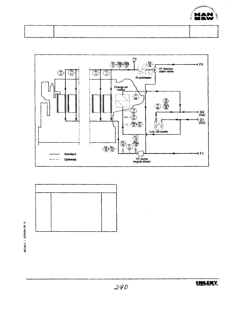
Fig 1 Diagram for infernal cooling water system 1.
|
Pipe description |
|
F3 |
Venting to expansion tank |
DN 15 |
G1 |
LT fresh water inlet |
DN 80/100 |
G2 |
LT fresh water outlet |
DN 80/100 |
Flange connections are as standard according to DIN 2501
Description
The system is designed as a single-circuit with only two flange connections to the external centralized low temperature (LT) cooling water system.
The engine is equipped with a self-controlling high temperature (HT) water circuit for cooling of cylinder liners and cylinder heads. Thus the engine on the cooling water side only requiresone fresh water cooler and so the engine can be intergrated in the ships cooling water system as as a stand alone unit, in a simple way, with low installation costs, which can be interesting in case of repowering, where the engine power is increased, and the distance to the other engines is larger.
Low Temperature Circuit
The components for circulation and temperature regulation are placed in the external system.
9948
B 13 00 0 |
Internal Cooling Water System 1 |
L23/30H
1613575-7.3
Page 2 (2)
The charge air coolerand the lubricating oil cooler are siuated parallelly in order to have the lowest possible cooling water inlet temperature for both coolers.
The HT-circuit is cooled by adjustment of water from the LT-circuit, taken from the lubricating oil cooler outlet. Thus the amount of cooling water through the cooling system is always adjusted to the engine load.
High Temperature Circuit
The built-on engine driven HT-circulating pump of the centrifugal type, pumps water through a distributing pipe to bottom of the cooling water space between the liner and the frame of each cylinder unit.The water is led out through bores in the top of the frame via the cooling waterguidejacket to the bore cooled cylinder head for cooling of this and the valve seats.
From the cylinder heads the water is led through a common outlet pipe to the thermostatic valve, and depending on the engine load, a smaller or larger amount ofthe water will be led to the external system or be re-circulated.
Optionals
Alternatively the engine can be equipped with the following:
—Thermostatic valve on outlet LT-system
-Engine driven pump for LT-system
-Preheater arrangement in HT-system
Branches for:
-External preheating
-Alternator cooling
If the alternator is cooled by water, the pipes for this can be integrated on the GenSet.
Data
For heat dissipation and pump capacities, See D 10 05 0, "List of Capacities".
Set points and operating levels for temperature and pressure are stated in B19 00 0, "Operating Data and Set Points".
Other design data are stated in B 13 00 0, "Design Data for the External Cooling Water System".
9948
1613576-9.3 Page 1 (2)
Internal Cooling Water System 2 |
B 13 00 0 |
|
L23/30H |
Fig 1 Diagram for internal cooling water system 2.
Pipe description
F1 |
HT fresh water inlet |
DN 80 |
F2 |
HT fresh water outlet |
DN80 |
F3 |
Venting to expansion tank |
DN 15 |
G1 |
LT fresh water inlet |
DN 80/100 |
(G3) |
LT sea water inlet |
DN 80/100 |
32 |
LT fresh water outlet |
DN 807100 |
(054) |
LT sea water outlet |
DN 80/100 |
Flange connectors are as standard according to DIN 2501
Description
The system is designed with separate LTand HTcircuits and is fully integrated in the external system, which can be a conventional or a centralized cooling water system. With this system pumps and heat exchangers can be common for propulsion and alternator engines. It is however, recommended that the alternator engines have separate temperature regulation on the HT-circuit.
Low Temperature (LT) Circuit
As standard the system is prepared forfresh water in the LT system, with pipes made of steel and the plates in the lub. oil cooler is made of stainless steel, but as optional, sea watercan be used provided that the materials used in the system are adjusted accordingly.
99 48

B 13 00 0 |
Internal Cooling Water System 2 |
L23/30H
1613576-93 Page 2 (2)
High Temperature (HT) Circuit
From the external HT-system, water is led through a distributing pipe to bottom ofthe cooling water space between the liner and the frame of each cylinder unit. The water is led out through bores in the top of the frame via the cooling water guide jacket to the bore cooled cylinder head for cooling of this and the valve seats.
From the cylinder heads the water is led through a common outlet pipe to the external system.
-Thermostatic valve on outlet, LT-system
-Thermostatic valve on outlet, HT-system
— Engine driven pump for LT-system
-Engine driven pump for HT-system
-Preheaterarrangement in HT-system
Branches for:
-External preheating
-Alternator cooling
If the alternator is cooled by water, the pipes for this can be integrated on the GenSet.
Qptionals
Alternatively the engine can be equipped with the following:
-LT-system cooled by sea water
which includes Titanium plates in the lub. oil cooler, LT-water pipes are made of aluminium brass or galvanized steel, covers for charge air cooler are made of bronze:
Data
For heat dissipation and pump capacities, see D 10 05 0 "List of Capacities".
Set points and operating levels for temperature and pressure are stated in B19 00 0 "Operating Data and Set Points".
Other design data are stated in B13 00 0 "Design Data for the External Cooling Water System".
9948
1613577-0.1 Page 1 (2)
Internal Cooling Water System 3 |
B 13 00 0 |
L23/30H
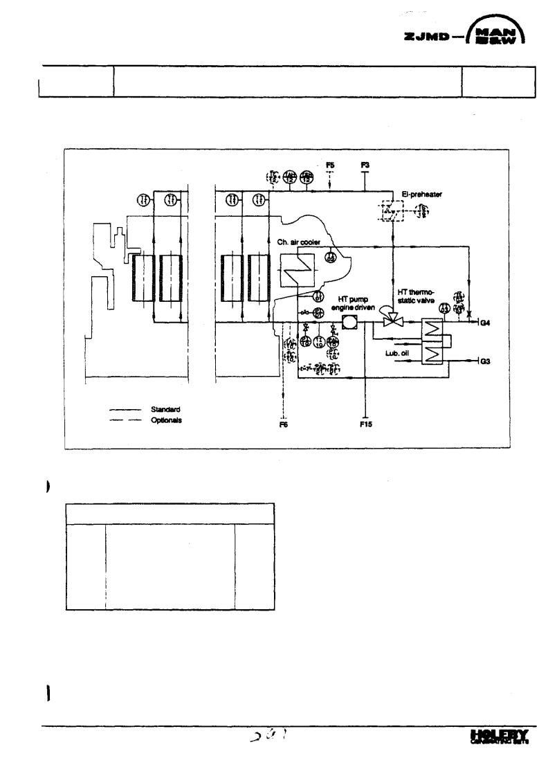
Fig. 1. Diagram for Internal Cooling Water System 3.
|
Pip* description |
|
F3 |
Venting to expansion tank |
DN15 |
F5 |
HT FW from preheater inlet |
DN15 |
F6 |
HT FW to preheater outlet |
ON 15 |
F15 |
Inlet from expansion tank |
DN15 |
G3 |
LT sea water inlet |
ON 100 |
G4 |
LT sea water outlet |
DN100 |
Flange connections are as standard according to DIN 2501
Description
The system is designed as a single-circuit with only two flange connections to an external sea water system.
This means that the system only require few components in the external system and that the engine can beintegrated intheshipscoolingwatersystem, on a simple and easy way with low installation cost.
The system is well suited for e.g. repowering, where a new engine - often with larger capacity - has to be adjusted to an existing system or by new platns, where the distance to the other engines is larger.
Low Temperature (LT) Circuit
Seawateris ledthroughthecombi-coolerwherethe HT fresh water and the lubricating oil are cooled and parallel with this through the charging air cooler.
91.34

B 13 000 |
Internal Cooling Water System 3 |
1613577-0.1 Page 2 (2)
L23/30H
As standard for this system, the plates in the combicooler are made of titanium and the covers in the charge air cooler are made of bronze, depending on choise the built-on pipes are made of aluminium breass or galvanized steel.
High Temperature (HI) Circuit
The engine is equipped with a self-controlling high temperature fresh water circuit.
The built-on engine driven HT-circulating pump of the centrifugal type, pumps water through a distributing pipe to bottom of the cooling water space betweenthe linerandtheframeofeachcylinderunit. The water is led out through bores in the top of the frame via the cooling water guide jacket to the bore cooled cylinder head for cooling ofthis and the valve seats.
From the cylinder head the water is led through a common outlet pipe to the built-on thermostatic valve, and depending on the engine load, a smaller or greater part of the water will be lead to the cooler or be re-circulated.
Optionals
The low-load version of this system is shown on B 13 00 0 "Internal Cooling Water System 6".
Alternatively the engine can be equipped with the following:
LT-cooling water pipes in aluminium brass or in galvanized steel
Preheater arrangement in HT-system
Branches for:
External preheating
Alternator cooling
If the alternator is cooled by water, the pipes for this can be integrated on the GenSet.
Data
For heat dissipation and pump capacities, see D 10 05 0 "List of Capacities".
Set points and operating levels for temperature and pressurearestatedin B1900 0"Operating Dataand Set Points".
Other design data are stated in B 13 00 0 "Design Data for the External Cooling Water System".
91