

7 семестр (Бормотов А) / 1man_bw_l23_30_chn_23_30_instruktsiya_po_ekspluatatsii_1 / MAN-BW L23-30 H Vol-1 (Instruction)+
.pdfWorking Card |
Prelubricating Pump |
515-01.05 |
Page 3 (3) |
Edition 06H |
|
|
|
|
|
|
|
7)Take off the gear box (2), if necessary use a soft hammer for separation.
8)Remove the gear wheels from the cover (1). Dismounting is only possible by disturbing the rotor shaft seal and by breaking the bearing bush.
9)Remove the security ring (11) and take off the rotary shaft seal (16).
10)Press out the driving gear shaft bearing bush, pull out the running bearing bush with the inner wheel puller.
11)Gear box (2). Dismounting is only possible by damaging the shaft bush. Press out the shaft bushes.
12)Pressure control valve (3). The pressure control valve can be dismounted also without dismounting the pump.
L23/30H
Mounting.
13) The mounting process follows in reverse order, it is stressed that an exact cleaning works is necessary.
Especially the sealing faces must be clean.
Tightening of screw pos. (9):
R25 10 Nm
R35 50 Nm
In connection with the bearing bush, attention must be paid to the placement of the butt joint and the mounting depth.
The new shaft seal cannot be pressed into the protection cover before exact mounting of the pump.
O-ring must be changed.
08028-0D/H5250/94.08.12
02.19 - ES0

Working Card |
Lubricating Oil Filter |
515-01.10 |
Page 1 (3) |
Edition 01H |
|
|
|
|
|
|
|
08028-0D/H5250/94.08.12
L23/30H
Safety precautions:
Stopped engine

 Shut-off starting air
Shut-off cooling water
Shut-off fuel oil
Shut-off cooling oil
Stopped lub. oil circul.
Description:
Replacement of paper filter element(s). Cleaning of safety filter and filter housing.
Starting position:
Related procedure:
Manpower: |
|
|
|
Working time |
: |
2 |
hours |
Capacity |
: |
1 |
man |
Data: |
|
|
|
Data for pressure and tolerance |
(Page 500.35) |
Data for torque moment |
(Page 500.40) |
Declaration of weight |
(Page 500.45) |
Special tools:
Plate no |
Item no |
Note |
Hand tools:
Ring and open end spanner, 22 mm. Ring and open end spanner, 24 mm. Ring and open end spanner, 27 mm. Adjustable spanner.
Replacement and wearing parts:
Plate no |
Item no |
Qty. / |
51502 |
013 |
See plate 51502 |
51502 |
290 |
1/Filter. |
91.45 - ES0S-G
515-01.10 |
Lubricating Oil Filter |
Working Card |
Edition 01H |
Page 2 (3) |
|
|
|
|
|
|
|
L23/30H |
|
|
The lubricating oil filter is dimensioned so that each of the two filter parts has sufficent capacity to treat the amount of lubricating oil delivered by the pump.
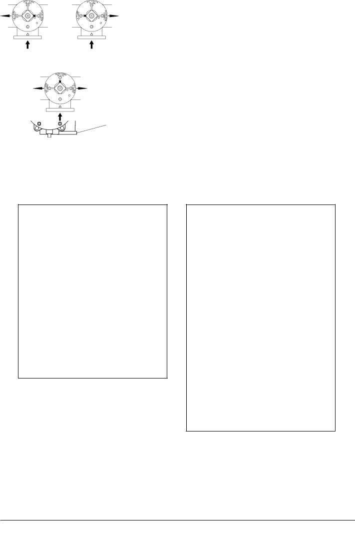
Thethree-wayvalvepositionedisdeterminingwhether the left hand or the right hand filter chamber is in operation, and also gives the possibility of having both filter chambers in operation simultaneously.
The three-way valve is marked with flow directions and the figure indicates the operation modes according to valve positions.
Three-way valve positions
Left hand filter |
Right hand filter |
camber in operation. |
camber in opera- |
|
tion. |
Both filter camber in operation.
Fig 1. Three-way valve positions.
Service Procedure.
1)Turn the three-way valve, see fig 2, into the position setting the stand-by filter chamber in operation and the filter chamber requiring service out of operation.
2)Open the vent screw (5) on the top of the filter to get the pressure out of the filter half.
3)Open the drain plug (8) under the filter housing and drain off oil.
4)Filter housing cap is dismantled.
5)Remove the inner safety element. Clean the element with detergent. Check that it is intact.
6)Remove the outer element(s). Filter element is of disposable type. It change always to new original filter.
7)Clean the filter housing and the cap. Be careful of not to let the oil from the dirty side to go into the clean oil channel in the middle of bottom.
8)Check the seal on the bottom of the filter
|
5 |
|
|
6 |
5 |
|
8 |
1 |
|
2 |
8 |
|
|
|
|
|
6 |
|
4 |
|
|
|
7 |
|
|
|
|
|
|
|
|
|
|
|
3 |
1 |
Left hand filter camber |
2 |
Right hand filter chamber |
||
3 |
Inlet |
|
4 |
Outlet |
|
5 |
Vent screw |
|
6 |
Three-way valve/ |
|
|
|
|
|
switch valve |
|
7 |
Fill-up valve |
|
8 |
Drain plug |
|
Fig 2.
housing and in the cap. Change if needed.
9)Assemble the filter in opposite order.
10)Let the air valve be open and fill the filter
08028-0D/H5250/94.08.12
91.45 - ES0S-G

Working Card |
Lubricating Oil Filter |
515-01.10 |
Page 3 (3) |
Edition 01H |
|
|
|
|
|
|
|
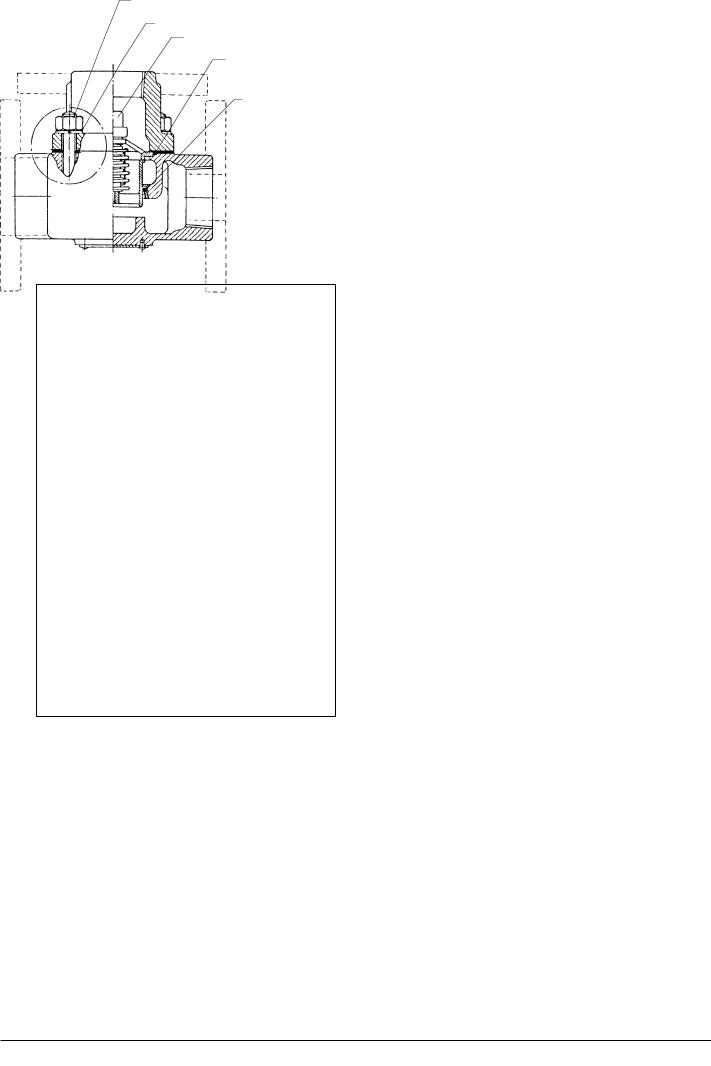
Fill-up valve positions
Operation |
Changing over |
Switch in normal |
Switch in fill |
operation position |
position |
Fig 3. Fill-up valve position.
L23/30H
housing with oil by means of the slow fill-up valve (7) in position FILL, see fig 3. This valve is inside the three-way valve and by using it, the filling can be made so slowly that the pressure on the other part of the filter does not drop too much.
11)Close the vent screw (5) after the housing is filled up with oil.
12)Open the three-way valve (6) and close the fillup valve (7) by turning it to position CLOSED, see fig. 3.
13)The filter just serviced is now ready to be set in operation.
Inspect for oil leakages in order to ascertain all sealings to be tight.
Check that pressure drop across filter is correct.
Clean the other side of the filter correspondingly.
08028-0D/H5250/94.08.12
91.45 - ES0S-G

Working Card |
Lubricating Oil, Thermostatic Valve |
515-01.20 |
Page 1 (2) |
Edition 01H |
|
|
|
|
|
|
|
08028-0D/H5250/94.08.12
L23/30H
Safety precautions:
Stopped engine

 Shut-off starting air
Shut-off cooling water
Shut-off fuel oil
Shut-off cooling oil
Stopped lub. oil circul.
Description:
Inspection of thermostatic valve and replacement of elements.
Starting position:
Lubricating oil drained from engine (if necessary).
Related procedure:
Manpower: |
|
|
|
Working time |
: |
2 |
hours |
Capacity |
: |
1 |
Man |
Data: |
|
|
|
Data for pressure and tolerance |
(Page 500.35) |
Data for torque moment |
(Page 500.40) |
Declaration of weight |
(Page 500.45) |
Special tools:
Plate No |
Item No |
Note |
Hand tools:
Ring and open end spanner 24 mm Copaslip
Tools and cleaning preparation for cleaning.
Replacement and wearing parts:
Plate No |
Item No |
Qty/ |
51503 |
020 |
2/engine |
51503 |
044 |
2 /engine |
51503 |
093 |
3/engine |
92.05 - ES0S-G
515-01.20 |
Lubricating Oil, Thermostatic Valve |
Working Card |
Edition 01H |
Page 2 (2) |
|
|
|
|
|
|
|
L23/30H
The thermostatic valve cannot be adjusted and under normalworkingconditionsmaintenanceisnotrequired. However, in some cases it is necessary to replace the elements in the thermostatic valve.
1
2
3
5
4
1.Nut
2.Washer
3.Element
4.O-rings sealing
5.Gasket
Fig 1 Thermostatic valve
Replacement of elements:
1)Remove nuts (1) and washers (2), 4 or 6 pcs. See fig 1.
2)Disconnect upper and lower part of the housing.
3)Remove the assembled elements (3) and the elements O-ring sealing.
4)Remove the gaskets between the upper and lower part of the housing.
5)The upper and lower part of the housing are thoroughly cleaned inside and on the gasket surfaces.
6)The sealing rings (4) for the elements in the housing are replaced and lubricated with a thin layer of copaslip.
7)Remounttheassembledelementsinthehousing by wriggling these somewhat over side.
8)Upper and lower part of the housing are assembled with a new gasket (5), the nuts (1) are mounted and tightened "cross-wise".
Note:
After inspection or replacement of the elements the lub. oil temperature is checked to ensure that the elements are working correctly.
08028-0D/H5250/94.08.12
92.05 - ES0S-G

Working Card |
Check of Lubricating Oil Piping System |
515-01.90 |
Page 1 (2) |
Edition 01H |
|
|
|
|
|
|
|
|
|
L23/30H |
08028-0D/H5250/94.08.12
Safety precautions: |
Special tools: |
|
|
Stopped engine |
Plate no |
Item no |
Note |
Shut-off starting air |
|
|
|
Shut-off cooling water |
|
|
|
Shut-off fuel oil |
|
|
|
Shut-off cooling oil |
|
|
|
Stopped lub. oil circul. |
|
|
|
Description: |
|
Check and examination of the lubricating oil piping |
|
system. |
Hand tools: |
Starting position:
Engine running.
Related procedure:
Manpower: |
|
|
|
Replacement and wearing parts: |
||
Working time |
: |
½ |
hour |
Plate no |
Item no |
Qty / |
Capacity |
: |
1 |
man |
|
|
|
Data: |
|
|
|
|
|
|
Data for pressure and tolerance |
(Page 500.35) |
|
|
|||
Data for torque moment |
|
(Page 500.40) |
|
|
||
Declaration of weight |
|
|
(Page 500.45) |
|
|
|
92.04 - ES0U-G

515-01.90 |
Check of Lubricating Oil Piping System |
Working Card |
Edition 01H |
Page 2 (2) |
|
|
|
|
|
|
|
L23/30H |
|
|
Checks to be carried out.
1)Examine the piping system for leaks.
2)Retighten all bolts and nuts in the piping system.
3)Move all valves and cocks in the piping system. Lubricate valve spindles with graphite or similar.
4)Blow-through drain pipes.
5)Check flexible connections for leaks and damages.
6)Checkmanometersandthermometersforpossible damages.
For lubricating oil condition, see section 504.
08028-0D/H5250/94.08.12
92.04 - ES0U-G

Working Card |
Lubricating Oil Cooler |
515-06.00 |
Page 1 (4) |
Edition 02H |
|
|
|
|
|
|
|
08028-0D/H5250/94.08.12
L23/30H
Safety precautions:
Stopped engine

 Shut-off starting air
Shut-off cooling water
Shut-off fuel oil
Shut-off cooling oil
Stopped lub. oil circul.
Description:
Separation, cleaning and assembling. Replacement of plates and gaskets.
Starting position:
Cooling water and lub. oil have been drained from cooler/engine. All pipes are disconnected.
Related procedure:
Manpower: |
|
|
|
Working time |
: |
4 |
hours |
Capacity |
: |
1 |
man |
Data: |
|
|
|
Data for pressure and tolerance |
(Page 500.35) |
Data for torque moment |
(Page 500.40) |
Declaration of weight |
(Page 500.45) |
Special tools:
Plate No |
Item No |
Note |
Hand tools: |
|
Ring and open end spanner |
10 mm |
Ring and open end spanner |
55 mm |
Ring and open end spanner |
30 mm |
Adjustable spanner |
|
Replacement and wearing parts:
Plate No |
Item No |
Qty./ |
51506 |
111/279 |
4/cooler |
96.39 - ES0S

515-06.00 |
Lubricating Oil Cooler |
Working Card |
Edition 02H |
Page 2 (4) |
|
|
|
|
|
|
|
L23/30H
Introduction
Cleaning of the cooler has to take place, when the pressure drop on the oil and water side is larger than allowable and/or if the oil cannot be sufficiently cooled.
Separation
Cooling and Pressure Relief
Before opening the plate heat exchanger, it has to be cooled down to below 40o C and be without pressure!
The cooling must not exceed 10o C per minute. The pressure drop must not exceed 10 bar per minute.
Note: If these norms are exceeded, the guarantee will cease to be valid.
Separation of Edge-clamped Frame
Upon completion of the procedure “Cooling and Pressure Relief”, separate the frame by retaining two or four diagonally placed bolts.
Note: Take care that the pressure plate does not tilt!
Loosen the bolts uniformly and diagonally (max. 10 mm at a time), then push the pressure plate towards the end support. When the pressure plate is not tight anymore, the plates can be removed.
Note: When using plate heat exchangers on board ships, the pressure plate have to be secured in order to avoid danger due to the movements of the ship.
Cleaning
The capacity and corrosion resistance of the plate heat exchangers depend on the purity of the plates. Any coating on the plates can be removed manually.
Manual Cleaning
Clean the plates with a soft brush and a suitable detergent. In case of dense coating of scale or organic materials, the plates must be put in a bath of detergent.
Note: Never use a steel brush, metal scraper or the like.
A high-pressure cleaner can be used with care, however, never with sand or other abrasives added.
Detergents
A detergent is suitable, if it will remove any coating on the plates without causing any damage to plates and gaskets.
Note: It is of great importance that decomposition of the protective film on the stainless steel does not take place - the film preserves the corrosion resistancy of the steel.
Do not use chlorine-containing agents such as hydrochloricacid (HCI)!
Oil and fats are removed by using a water emulsifying oil solvent, e.g. BP-system cleaner.
Organic and greasy coatings are removed by using sodium hydroxide (NaOH):
-max. concentration 1.5%
(1.5% concentration corresponds to 3.75 l
30% NaOH per 100 l water).
-max. temperature 85o C.
Stone and lime/calcareous deposits are removed by using nitric acid (HNO3):
-max. concentration 1.5%
(1.5% concentration corresponds to 1.75 l
62% HNO3 per 100 l water).
-max. temperature 65o C.
Note: The nitric acid has an important constructive effect on the protective film of stainless steel.
08028-0D/H5250/94.08.12
96.39 - ES0S