

7 семестр (Бормотов А) / 1man_bw_l23_30_chn_23_30_instruktsiya_po_ekspluatatsii_1 / MAN-BW L23-30 H Vol-1 (Instruction)+
.pdf514-01.15 |
Fuel Oil Split Filter |
Working Card |
Edition 01H |
Page 2 (2) |
|
|
|
|
|
|
|
L23/30H
1)During normal operation both filters should be in operation, single operation only to be used when dismantling one of the filters for manual cleaning or inspection.
2)Normally the filters are cleaned during operation by turning the handle, (1) see fig 1, on the filter housing top a couple of turns. (clockwise).
Simultaneously with turning of the handle, the drain cock, (2) in bottom of the filter housing should be opened in order to drain of the dirt being scraped of the filter element, (3).
1
5
3
2
Fig 1 Fuel oil split filter
3)Position of three way cock, see fig 2.
|
|
4 |
5 |
Left Filter |
Both filters in |
Right |
Filter |
This position is |
operation. |
This position is |
|
only for cleaning |
|
only for cleaning |
|
of the right filter, |
|
of the left filter, |
|
not for continu- |
|
not for |
continu- |
ous operating. |
|
ous operating. |
|
Fig 2. Fuel oil split filter (top view).
Note: Shut-off fuel oil, before dismantling filter element.
4)If no drainage occurs when the drain cock is opened, the filter housing should be dismantled for manual cleaning. Remove the nuts (5), and take out the filter element (3).
5)Clean the filter element in kerosene gas oil or similar and blow it dry with working air.
6)Mount the filter element again.
7)The filter element itself should never be dismantled, but has to be replaced if damage or mal function is experienced.
08028-0D/H5250/94.08.12
91.08 - ES0S-G

Working Card |
Check of Fuel Oil Piping System |
514-01.90 |
Page 1 (2) |
Edition 01H |
|
|
|
|
|
|
|
08028-0D/H5250/94.08.12
L23/30H
V28/32S
Safety precautions |
Special tools |
|
|
Stopped engine |
Plate no |
Item no |
Note |
Shut-off starting air |
|
|
|
Shut-off cooling water |
|
|
|
Shut-off fuel oil |
|
|
|
Shut-off cooling oil |
|
|
|
Stopped lub. oil circul. |
|
|
|
Press Blocking - Reset |
|
|
|
Description |
|
|
|
Check of fuel oil piping system. |
Hand tools |
|
|
|
|
|
Starting position
Engine is running.
Related procedure
Manpower |
|
|
|
Replacement and wearing parts |
||
Working time: |
|
|
½ hour |
Plate no |
Item no |
Qty / |
Capacity |
: |
1 |
man |
|
|
|
Data |
|
|
|
|
|
|
Data for pressure and tolerance |
(Page 500.35) |
|
|
|||
Data for torque moment |
|
(Page 500.40) |
|
|
||
Declaration of weight |
|
|
(Page 500.45) |
|
|
|
92.04 - ES0S-G

514-01.90 |
Check of Fuel Oil Piping System |
Working Card |
Edition 01H |
Page 2 (2) |
|
|
|
|
|
|
|
L23/30H |
|
|
V28/32S |
|
|
Fuel Oil System
1)Dismount the covers to the injection pumps. Blow-through drain pipes.
2)Examine the piping system for leaks.
3)Retighten all bolts and nuts in the piping system.
4)Move all valves and cocks in the piping system.
Lubricate valve spindles with graphite or similar.
5)Check flexible connections for leaks and damages.
6)Check the condition of the lower O-ring for the fuel injecting valves by means of the venting pipe.
For fuel oil condition, see section 504.
Venting pipe
Fig 1. Cross section of cylinder head
08028-0D/H5250/94.08.12
92.04 - ES0S-G

Working Card |
Adjustment of The Maximum Combustion Pressure |
514-05.01 |
Page 1 (3) |
Edition 01H |
|
|
|
|
|
|
|
|
|
L23/30H |
08028-0D/H5250/94.08.12
Safety precautions:
Stopped engine

 Shut-off starting air
Shut-off cooling water
Shut-off fuel oil
Shut-off cooling oil
Stopped lub. oil circul.
Description:
Adjustment of the maximum combustion pressure for the cylinders one by one and for all cylinders in total.
Starting position:
Camshaft mounted and adjusted in
relation to the crankshaft (lead), 507-01.20 Intermediate wheel mounted.
Related procedure:
Manpower: |
|
|
|
Working time |
: |
2-5 |
hours |
Capacity |
: |
1 |
man |
Data: |
|
|
|
Data for pressure and tolerance |
(Page 500.35) |
Data for torque moment |
(Page 500.40) |
Declaration of weight |
(Page 500.45) |
Special tools: |
|
|
Plate no |
Item no |
Note |
52006 |
261 |
20 - 120 Nm. |
52010 |
011 |
|
52008 |
058 |
|
Hand tools:
Ring and open end spanner, 19 mm. Socket spanner, 19 mm.
Depth gauge. Plastic hammer.
Replacement and wearing parts:
Plate no |
Item no |
Qty / |
50801 |
124 |
1 set/cyl |
91.45 - ES0S-G
514-05.01 |
Adjustment of The Maximum Combustion Pressure |
Working Card |
Edition 01H |
Page 2 (3) |
|
|
|
|
|
|
|
L23/30H
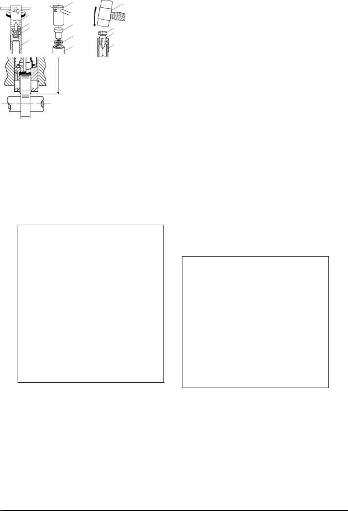
If fuel oil valve, piston, inlet and exhaust valves as well as turbocharger and charge air cooler are working correct and the compression pressure Pcomp is normal the maximum combustion pressure will indicate the injection timing for the fuel oil pump.
If Pmax is too low it indicates that the injection timing is delayed.
If Pmax is too high it indicates that the injection timing is advanced.
The injection timing can be altered by inserting or removing shims under the thrust piece on the roller guide, thus changing the measure “X”, see fig 1.
Measure "x"
Total height
Fig 1
Thinner and/or fewer shims (increase of the distance “X”) results in a delayed injection timing and a lower
Pmax.
Thicker and/or more shims (reduction of the distance “X”) results in an advanced injection timing and a higher Pmax.
If the distance “X” is to be changed the trigger (1) is used for dismantling of the thrust piece (2), whereafter the thickness and/or the number of shims (3) can be changed.
By changing “X” with 0.10 mm the maximum combustion pressure is changed with - see page 500.35.
After replacement of shims the thrust piece is remounted in the roller guide (4) with a soft hammer (5).
When changing “X” it must be ensured that the
|
|
|
5 |
1 |
Extractor |
2 |
Thrust piece |
3 |
Shims |
4 |
Roller guide |
5 |
Soft hammer |
|
|
Fig 3
|
|
|
|
|
|
|
|
0D/H5250/94.08.12-08028 |
Action |
|
|
|
Results |
|
|
|
|
|
|
|
|
|
|
|
||
|
|
|
|
|
|
|
|
|
Total height |
|
Distance |
|
Injection |
|
Max. combustion |
|
|
on roller guide |
|
"x" |
|
timing |
|
pressure |
|
|
|
|
|
|
|
|
|
|
|
increased |
- |
Reduced |
¯ |
Advanced |
- |
increased |
- |
|
|
|
|
|
|
|
|
|
|
Reduced |
¯ |
increased |
- |
Delayed |
¯ |
Reduced |
¯ |
|
|
|
|
|
|
|
|
|
|
Fig 2
91.45 - ES0S-G
Working Card |
Adjustment of The Maximum Combustion Pressure |
514-05.01 |
Page 3 (3) |
Edition 01H |
|
|
|
|
|
|
|
|
|
L23/30H |
distance between the upper edge of the roller guide housing and the thrust piece on the roller guide is not exceeded, when the roller is resting on the circular part of the fuel cam, see page 500.35.
In all cases “X” must be checked and adjusted, if necessary, when fuel oil pump, roller guide, roller guide housing and/or camshaft section have been replaced/dismantled.
Note: If several fuel oil pumps, roller guides, roller guide housings and/or camshaft sections are dismantled at the same time it is advisable to number the parts in order to facilitate remounting and adjustment.
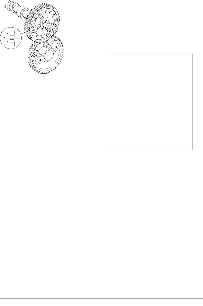
If the maximum combustion pressure differs from the test bed records after adjustment of each individual pump the camshafts placement can be changed, as thecamshaftsgearwheelsareprovidedwithoblonged holes so that they can be turned in relation to the hub.
The gear wheel is provided with an engraved scale, see fig 4, and the hub of the cam shaft is provided with a mark.
When the screws, which fasten the gear wheel, are loosened the gear wheel is turned (by turning the crankshaft) in relation to the camshaft. By reading the angle in which the gear wheel is displaced in relation to the camshaft the altered Pmax can be calculated. A line on the scale corresponds to: see page 500.35.
If the crankshaft is turned in the engines normal direction of rotation the maximum combustion pressure P-max. is reduced.
Fig. 4
If the crankshaft is turned against the engines normal direction of rotation the maximum combustion pressure P-max. is increased.
After the adjustment the screws are fastened with a torque wrench, see page 500.40, and secured.
08028-0D/H5250/94.08.12
91.45 - ES0S-G

Working Card |
Fuel Oil Feed Pump |
514-10.00 |
Page 1 (3) |
Edition 01H |
|
|
|
|
|
|
|
08028-0D/H5250/94.08.12
L23/30H
Safety precautions:
Stopped engine

 Shut-off starting air
Shut-off cooling water
Shut-off fuel oil
Shut-off cooling oil
Stopped lub. oil circul.
Description:
Disassembly, overhaul and assembly of fuel oil feed pump.
Adjustment of fuel oil pressure.
Starting position:
All pipe connections to the feed pump have been disconnected, and the feed pump is removed from the engine.
Related procedure:
Man power: |
|
|
|
Working time |
: |
4 |
Hours |
Capacity |
: |
1 |
man |
Data: |
|
|
|
Data for pressure and tolerance |
(Page 500.35) |
Data for torque moment |
(Page 500.40) |
Declaration of weight |
(Page 500.45) |
Special tools:
Plate no. |
Item no. |
Note. |
Hand tools:
Allen key, 8 mm, 10 mm, 22 mm. Ring and open end spanner, 17 mm. Ring and open end spanner, 46 mm. Big screwdriver.
Adjustable spanner. Puller.
Hard brush. Gas oil.
Replacement and wearing parts:
Plate no. |
Item no. |
Qty. / |
51410 |
049 |
1/pump |
51410 |
050 |
4/pump |
51410 |
108 |
1/pump |
51410 |
265 |
1/pump |
96.26 - ES0S

514-10.00 |
Fuel Oil Feed Pump |
Working Card |
Edition 01H |
Page 2 (3) |
|
|
|
|
|
|
|
L23/30H
Disassembly.
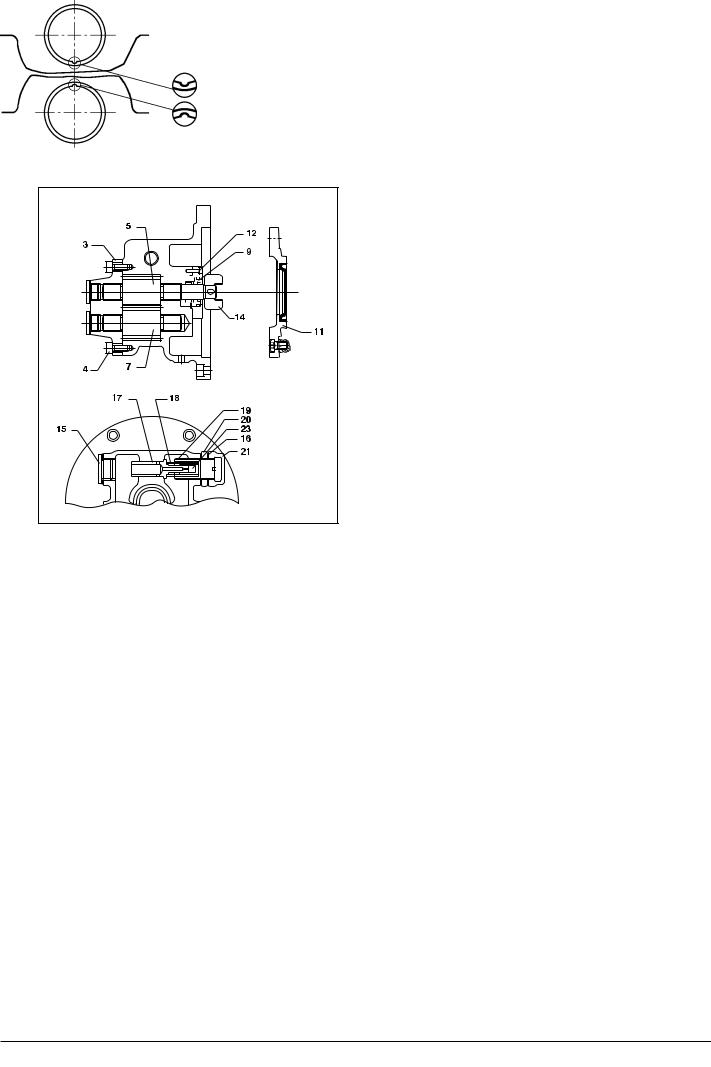
1)Remove the coupling part (14), see fig. 1, by means of a puller.
2)Remove screws (12) and dismount the cover (11) with locking ring, sealing ring, o-ring and rotating packing (9).
3)After removal of the screws (4) (6 pcs.) the cover (3) is dismantled and the gear wheels (5 and
7)are pulled out.
4)Dismounting of the spring loaded adjustable by-pass valve.
Remove the cap nut (21), nut (20), spring housing (19), spring (18) and the cylinder (23). If the piston (17) cannot be pulled out from the same side the plug screw (15) can be removed and the piston can be pressed from this side with a screw driver or the like.
Overhaul:
5) Clean all the parts with gas oil and a hard brush.
Warning: Never use a steel brush.
The parts are blown clean with working air.
6) If the bearing bush are to be removed the existing bearing bush is plugged out, the bores are cleaned and new bearing bush is mounted, see fig. 2.
Before the gear wheels can be mounted the bearing bush must be adjusted with a reamer or a bearing scraper, so that the gear wheel can run easily when the pump is assembled.
7)Renew the sealing ring in cover (11).
8)Inspect all other parts for wear and damage, and renew, if necessary.
Assembly:
9)Mount the gear wheel (5 and 7), coat the sealing lip with silastene or similar and mount the cover (3).
10)Mount the rotating packing (9) and the cover
(11)with sealing ring, o-ring, locking ring and coupling
(14).
11)Mount the spring loaded by-pass valve, nut (20), gasket (16), cap nut (21) and plug screw (15).
12)Mount the feed pump on the engine and connect all the pipes.
Adjusting of Fuel Oil Pressure.
13) The outlet pressure of the feed pump, can be adjusted by means of an adjusting screw in the bypass valve.
Remove the cap nut (21) and loosen the nut (20).
By turning the spring housing clockwise the pressure is raised and reverse the pressure is lowered by turning the spring housing (19) anti-clockwise. When the correct pressure is reached, see page 500.30, the spring housing (19) is locked with nut (20) and finally the gasket (16) and cap nut (21) are mounted.
08028-0D/H5250/94.08.12
96.26 - ES0S
Working Card |
|
|
|
|
|
|
|
Fuel Oil Feed Pump |
514-10.00 |
||
Page 3 (3) |
|
|
|
|
|
|
|
Edition 01H |
|||
|
|
|
|
|
|
|
|
|
|||
|
|
|
|
|
|
|
|
|
|
|
|
|
|
|
|
|
|
|
|
|
|
L23/30H |
|
|
|
|
|
|
|
|
|
|
|
|
|
|
|
|
|
|
|
|
|
|
|
|
|
|
|
|
|
|
|
|
|
|
|
|
|
|
|
|
|
|
|
|
|
|
|
|
|
|
|
|
|
|
|
|
|
|
|
|
|
|
|
|
|
|
|
|
|
|
|
|
|
|
|
|
|
|
|
|
|
|
|
|
|
|
|
|
|
|
|
|
|
|
|
|
|
|
|
|
|
|
|
|
|
|
|
|
|
|
|
|
|
|
|
|
|
|
|
|
|
|
|
|
|
|
|
|
|
|
|
|
|
Fig. 2. Mounting of bearing bush.
Fig. 1. Fuel oil feed pump.
08028-0D/H5250/94.08.12
96.26 - ES0S
Plate
Page 1 (2)
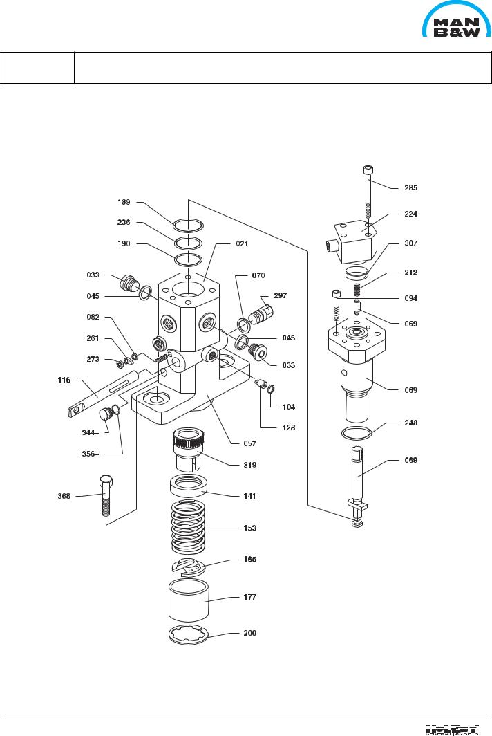
Fuel Injection Pump |
51401-01H |
|
|
L23/30H
08028-0D/H5250/94.08.12
03.36 - ES0