

7 семестр (Бормотов А) / 1man_bw_l23_30_chn_23_30_instruktsiya_po_ekspluatatsii_1 / MAN-BW L23-30 H Vol-1 (Instruction)+
.pdf50910-01H |
Lambda Controller |
|
|
L23/30H
Plate
Page 2 (2)
Item |
|
|
|
|
Item |
|
No. |
Qty. |
Designation |
Benævnelse |
|
No. Qty. Designation |
Benævnelse |
|
|
|
|
|
|
|
019 |
1/E |
Regulating arm, |
Reguleringsarm, |
|
|
|
|
|
complete |
komplet |
|
|
|
020 |
1/E |
Pick-up, |
Pick-up, |
|
|
|
|
|
incl. sleeve |
incl. afstandsring |
|
|
|
032 |
1/E |
Lambda cylinder, |
Lambdacylinder, |
|
|
|
|
|
complete |
komplet |
|
|
|
When ordering spare parts, see also page 500.50.
* |
= Only available as part of a spare parts kit. |
Qty./E |
= Qty./Engine |
08028-0D/H5250/94.08.12
Ved bestilling af reservedele, se også side 500.50.
* |
= |
Kun tilgængelig som en del af et reservedelssæt. |
Antal/E = |
Antal/Motor |
|
97.14 - ES0S

Index
Pagel (1)
Description
Crankshaft and Main Bearings |
510 |
L23/30H
Crankshaft and Main |
Bearings................................................................... |
510.01.(01H) |
|||
Working Card |
|
|
|
|
|
Checking of Main Bearing Alignment (autolog).......................................... |
510-01.00.(01H) |
||||
Inspection of Main Bearing |
Shells............................................................. |
510-01.05.(01H) |
|||
Inspection of Guide Bearing |
Shells............................................................ |
510-01.10.(01H) |
|||
Flywheel Self-locking Nut's Tightening Addition Instruction..................... |
510-03.00.(01Z) |
||||
Vibration Damper........... |
|
................................................................................. |
|
510-04,00.(01H) |
|
Plates |
|
|
|
|
|
Crankshaft |
............ |
................................................................................................. |
|
|
51001-04H |
Crankshaft............ |
|
............ |
..................................................................................... |
|
51001-04Z |
Coupling for Central Driven Lub. Oil Pump................................................... |
51002-01H |
||||
Resilient |
Gear |
Wheel......................................................................................... |
|
51002-02H |
|
Flywheel with Flexible Coupling and Gear Rim.............................................. |
51003-01H |
||||
Flywheel |
with |
Gear |
Rim............................................................................... |
51003-02H |
|
Flywheel |
with |
Gear |
Rim............................................................................... |
51003-03H |
|
Torsional |
Vibration |
Damper....................................................................... |
51004-01H |
||
Tuning Wheel.................................................................................................. |
|
|
|
51004-02H |
|
98.35 - ESOU

Description |
Crankshaft and Main Bearings |
510.01 |
Page 1 (1) |
Edition 01H |
|
|
|
|
|
|
|
|
|
L23/30H |
Crankshaft |
Vibration Damper |
|
The crankshaft, which is a one-piece forging with ground main bearing and crankpin journals, is suspended in inderslung bearings. The main bearings are equipped with insertion-type shells, which are coated with a wearing surface. To attain a suitable bearing pressure the crankshaft is provided with counterweights, which are attached to the crankshaft by means of two screws.
At the flywheel end the crankshaft is fitted with a gear wheel which through an intermediate wheel drives the camshaft. Also fitted here is the flywheel and a coupling flange for connection of a reduction gear or an alternator. At the opposite end there is a claw-type coupling for the lub. oil pump or a flexible gear wheel connection for lub. oil and water pumps.
In special cases a vibration damper is mounted on the crankshaft to limit torsional vibrations. The damper consists essentially of a heavy flywheel totally enclosed in a light casing. A small clearance is allowed between the casing and the flywheel, and this space is filled with a highly viscous fluid. The casing is rigidly connected to the front end of the engine crankshaft and the only connection between the crankshaft and the damper flywheel is through the fluid. Under conditions of no vibration, the casing and damper flywheel tend to rotate as one unit, since the force required to sheartheviscousfilmisconsi-derable.Asthetorsional vibration amplitudes increase, the casing follows the movement of the crankshaft but the flywheel tends to rotate uniformly by virtue of its inertia, and relative motion occurs between the flywheel and the casing. The viscous fluid film therefore undergoes a shearing action, and vibration energy is absorbed and appears as heat.
08028-0D/H5250/94.08.12
96.03 - ES0U

Working Card |
Checking of Main Bearings Alignment (Deflection) |
510-01.00 |
Page 1 (7) |
(Hydraulic Tightened Connecting Rod) |
Edition 04H |
|
||
|
|
L23/30H |
08028-0D/H5250/94.08.12
Safety precautions: |
Special tools: |
|
|
||
|
|
Stopped engine |
Plate no. |
Item no. |
Note |
|
|||||
|
|
Shut-off starting air |
|
|
|
|
|
|
|
|
|
|
|
Shut-off cooling water |
52010 |
011 |
|
|
|
Shut-off fuel oil |
52010 |
059 |
|
|
|
Shut-off cooling oil |
52010 |
358 |
|
|
|
Stopped lub. oil circul. |
|
|
|
|
|
|
|
||
Description: |
Hand tools: |
Checking of main bearings alignment (autolog).
Starting position:
Turning gear in engagement. (If mounted). Cover for crankshaft has been removed from frame.
All indicator valves open.
Related procedure:
Manpower: |
|
|
|
Replacement and wearing parts: |
||
Working time |
: |
1 1/2 |
hours |
Plate no |
Item no |
Qty / |
Capacity |
: |
2 |
men |
|
|
|
Data: |
|
|
|
|
|
|
Data for pressure and tolerance |
(Page 500.35) |
|
|
|||
Data for torque moment |
|
(Page 500.40) |
|
|
||
Declaration of weight |
|
(Page 500.45) |
|
|
||
00.27 - ES0
510-01.00 |
Checking of Main Bearings Alignment (Deflection) |
Working Card |
Edition 04H |
(Hydraulic Tightened Connecting Rod) |
Page 2 (7) |
L23/30H
Alignment of Main Bearings.
The lower main bearing shells should be positioned so that they keep the main bearing journals of the crankshaft centered in a straight (ashore horizontal) line. Deviations from this centre line cause the crankshaft to bend and increase the load on some main bearings.
If two adjacent main bearings are placed too low, the crankshaft centre line will in this place be lowered to form an arc, causing the intermediate crank throw to bend in such a way that it "closes" when turned into bottom position and "opens" in top position.
As the magnitude of such axial lengthening and shortening during the turning of the throw increases in proportion to the difference in the height of the bearing, it is measured as a check on the alignment and condition of the bearing.
As the crankshafts of medium speed engines are very stiff, any great deviations in the alignment will result in clearance at the bottom shell of the bearings.
The cause of incorrect main bearing position may be wear of the bearings or misalignmnet of the engine.
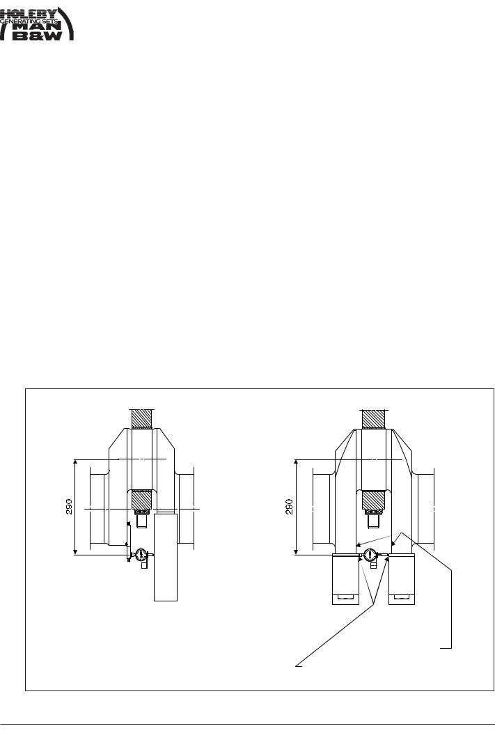
Effecting The Deflection Measurement.
The deflection measurement is effected by placing a springloaded dial gauge in the centre punch marks provided for this purpose, see fig. 1.
"Closing" of the throw in top dead centre is regarded as negative, (compression of the gauge).
In the example, page 3, the deflection reading is therefore negative.
Not for measuring (autolog)
Existing centre punch marks for measuring (autolog)
Fig. 1 Placing of dial gauge
08028-0D/H5250/94.08.12
00.27 - ES0

Working Card |
Checking of Main Bearings Alignment (Deflection) |
510-01.00 |
Page 3 (7) |
(Hydraulic Tightened Connecting Rod) |
Edition 04H |
|
||
|
|
L23/30H |
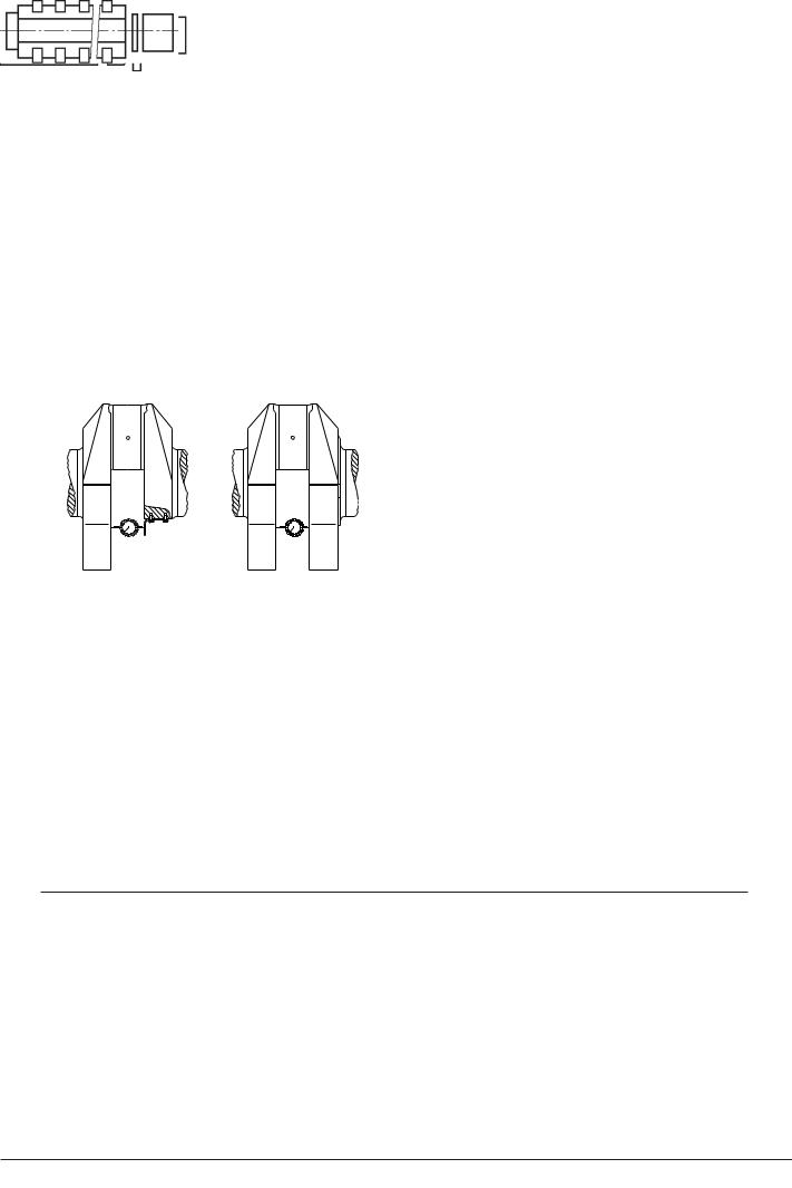
As during the turning of the throw, the gauge and the connecting rod will meet near the bottom position of the throw, the measurement for the bottom position is to be replaced by the average of the two near by positions on either side.
The dial gauge is set to zero, when the crank throw is in the near-bottom (x in fig. 8) and during the turning the throw is stopped in the position horizontal-top- horizontal-near bottom (P-T-S-Y in fig. 8) for reading of the gauge.
Checking The Deflection Measurement.
The reading is entered in the table page 6, see example in fig. 2 - 6.
As "bottom" reading is used the mean value of the two "near bottom" readings X and Y, fig. 3.
The total deflection ("opening-closing") of the throw during the turning from bottom to top position is entered in fig. 4.
These figures are due to vertical misalignment of the main bearings.
Similarly, horizontal misalignment procedures the figures in the table fig. 5.
Besides misalignment of the bearings, the readings can be influenced by ovality or eccentricity of the journals.
Engines Equipped with Turning Gear.
When taking these deflection readings for the three aftmost cylinders, the turning gear should at each stoppage be turned a little backwards to ease off the tangential pressure on the teeth of the turning wheel as this pressure may otherwise falsify the readings.
08028-0D/H5250/94.08.12
00.27 - ES0

510-01.00 |
Checking of Main Bearings Alignment (Deflection) |
Working Card |
Edition 04H |
(Hydraulic Tightened Connecting Rod) |
Page 4 (7) |
|
|
|
L23/30H
Deflection of crankshaft in 1/100 mm. (0.01 mm).
|
|
|
|
Cyl. No. |
|
|
|
Crank position |
|
1 |
2 |
3 |
4 |
5 |
6 |
|
|
|
|
|
|
|
|
Bottom start |
X |
0 |
0 |
0 |
0 |
0 |
0 |
Left side |
P |
2 |
0 |
2 |
0 |
-1 |
2 |
Top |
T |
3 |
-2 |
4 |
5 |
-2 |
3 |
Right side |
S |
3 |
-2 |
2 |
0 |
0 |
1 |
Bottom stop |
Y |
2 |
-1 |
0 |
1 |
0 |
2 |
|
|
|
|
|
|
|
|
Fig. 2. |
|
|
|
|
|
|
|
|
|
|
|
|
|
|
|
Bottom (0,5 x Y) = |
B |
1 |
-0.5 |
0 |
-0.5 |
0 |
1 |
|
|
|
|
|
|
|
|
Fig. 3. |
|
|
|
|
|
|
|
Deflection from vertical |
|
|
|
|
|
|
||
misalignment |
|
|
|
|
|
|
||
top - bottom |
|
|
|
|
|
|
|
|
or T - B = |
V |
2 |
-1.5 |
4 |
4.5 |
-2 |
2 |
|
|
|
|
|
|
|
|
|
|
Fig. 4. |
|
|
|
|
|
|
|
|
|
|
|
|
|
|
|
|
|
Deflection from hori- |
|
|
|
|
|
|
||
zontal misalignment |
|
|
|
|
|
|
||
Right side - left side |
|
|
|
|
|
|
||
or P - S = |
H |
-1 |
2 |
0 |
0 |
-1 |
1 |
|
|
|
|
|
|
|
|
|
|
Fig. 5. |
|
|
|
|
|
|
|
|
|
|
|
|
|
|
|
|
|
Check on |
|
T + B = C |
4 |
-2.5 |
4 |
5.5 |
-2 |
4 |
gauge |
|
|
|
|
|
|
|
|
readings |
|
P + S = D |
5 |
-2 |
4 |
0 |
-1 |
3 |
|
|
|
|
|
|
|
|
|
Fig. 6.
C and D should be nearly the same, reading for cylinder 4 to be repeated.
T
S
|
|
Front end view. |
"Closing" of the crankthrow is considered ne- |
Start in position X. |
|
gative. |
Turn anti clockwise |
|
|
|
|
Fig. 7. |
Fig. 8. |
|
08028-0D/H5250/94.08.12
00.27 - ES0

Working Card |
Checking of Main Bearings Alignment (Deflection) |
510-01.00 |
Page 5 (7) |
(Hydraulic Tightened Connecting Rod) |
Edition 04H |
|
||
|
|
L23/30H |
Measurement of Crank Throw Deflections by Means of Dial Indicator (Autolog)
Crank throw deflection |
= |
Difference in dial indicator readings in two diametrically |
|
|
opposite crank throw positions, i.e. two positions dis- |
|
|
placed 180°. |
Vertical deflection |
= |
Difference in top-bottom readings. |
Horizontal deflection |
= |
Difference in side-side readings. |
Vertical of Horizontal Deflections of Crank Throws
Unless otherwise stated the values refer to cold engine.
For new or realigned aggregate |
Aim for |
+ or - 3/100 |
mm |
|
Acceptable |
+ or - 5/100 |
mm |
For aggregate in service realignment |
|
|
|
is recommended if deflections exceed |
|
+ or - 9/100 |
mm |
08028-0D/H5250/94.08.12
Vertical Deflection of Crank Throw at Flywheel
Unless otherwise stated the values refer to cold engine.
Rigid coupling between |
|
|
Flexible coupling between |
|
|
||
diesel engine and driven machine |
diesel engine and driven machine |
||||||
For new or realigned |
|
|
|
For new or realigned |
|
|
|
aggregate |
0 to |
+ |
3/100 mm |
aggregate |
Aim for |
- 9/100 mm |
|
|
|
|
|
|
Acceptable |
- 11/100 mm |
|
For aggregate in service realignment is |
For aggregate in service |
|
|
||||
recommended if deflection measured |
realignment recommendable |
|
|
||||
on warm engine exceeds |
- |
9/100 mm |
if deflection exceeds |
- 16/100 mm |
|||
|
|
|
|
|
|
|
|
00.27 - ES0
510-01.00 |
|
Checking of Main Bearings Alignment (Deflection) |
|
Working Card |
|||||
Edition 04H |
|
|
(Hydraulic Tightened Connecting Rod) |
|
|
Page 6 (7) |
|||
L23/30H |
|
|
|
|
|
|
|
||
|
|
|
|
|
|
|
|
||
|
Process/Proces |
|
|
|
I.D. no. |
|
|
||
|
|
|
|
|
|
|
|
||
|
Plant/Anlæg |
|
|
|
Page of/Side af |
|
|
||
|
|
|
|
|
|
|
|||
|
Engine Type/Motortype |
|
Engineer/Operatør |
Date/Dato |
|
|
|||
|
|
|
|
|
|
|
|
||
|
Instruction/Instruktion |
|
|
|
|
|
|
||
Top
Right side
1/100 mm
Bottom end/ |
Bottom start/ |
Bund slut |
Bund start |
|
Right side |
|
Right side |
Cyl. no |
1 2 3 |
Cyl. no |
1 2 3 |
Left side |
Cyl. no |
1 2 3 |
|
|
Left side |
Remarks/Bemærkninger
08028-0D/H5250/94.08.12
00.27 - ES0

|
Working Card |
|
Checking of Main Bearings Alignment (Deflection) |
510-01.00 |
||||||||||||||||
|
Page 7 (7) |
|
|
(Hydraulic Tightened Connecting Rod) |
|
|
|
|
Edition 04H |
|||||||||||
|
|
|
|
|
|
|
|
|
||||||||||||
|
|
|
|
|
|
|
|
|
|
|
|
|
|
|
|
|
|
|
|
|
|
|
|
|
|
|
|
|
|
|
|
|
|
|
|
|
|
|
|
L23/30H |
|
|
|
|
|
|
|
|
|
|
|
|
|
|
|
|
|
|
|
|
|
|
|
|
Component/Komponent |
|
|
|
|
|
Type |
|
|
|
I.D. no. |
|
|
|
|||||
|
|
|
|
|
|
|
|
|
|
|
|
|
|
|
|
|
|
|
||
|
|
Process/Proces |
|
|
|
|
|
|
|
|
|
|
|
|
Page of/Side af |
|
||||
|
|
|
|
|
|
|
|
|
|
|
|
|
|
|
|
|
|
|
|
|
|
|
|
|
|
|
|
|
|
|
|
|
|
|
|
|
|
|
|
|
|
|
|
Test place/ |
|
|
Test |
bed/prøvehal |
|
Cold/Kold |
|
|
|
|
|
|
|
|
||||
|
|
Condition |
|
|
|
|
|
|
|
|
|
|
|
|
|
|
|
|
|
|
|
|
|
|
|
On board/Om bord |
|
Warm/Varm |
|
|
|
|
|
|
|
|
|||||
|
|
Teststed/ |
|
|
|
|
|
|
|
|
|
|
|
|
|
|
|
|
|
|
|
|
Tilstand |
|
|
Plant/Maskinhal |
|
|
|
|
|
|
|
|
|
|
|
|
|
||
|
|
|
|
|
|
|
|
|
|
|
|
|
|
|
|
|
|
|
|
|
|
|
Engine no.: |
|
|
|
|
|
|
|
|
|
|
|
|
|
|
|
|
|
|
|
|
Motornr.: |
|
|
|
|
|
|
|
|
|
|
|
|
|
|
|
|
|
|
|
|
|
|
|
|
|
|
|
|
|
|
|
|
|
|
|
|
|
|
|
|
|
Cyl. no. |
|
1 |
|
2 |
|
3 |
4 |
5 |
|
|
6 |
|
7 |
|
8 |
|
9 |
|
|
|
|
|
|
|
|
|
|
|
|
|
|
|
|
|
|
|
|
|
|
|
|
Bottom |
X |
0 |
|
0 |
|
0 |
0 |
0 |
|
|
0 |
|
0 |
|
0 |
|
0 |
|
|
|
|
|
|
|
|
|
|
|
|
|
|
|
|
|
|
|
|
|
|
|
|
Left side |
P |
|
|
|
|
|
|
|
|
|
|
|
|
|
|
|
|
|
|
|
|
|
|
|
|
|
|
|
|
|
|
|
|
|
|
|
|
|
|
|
|
Top |
T |
|
|
|
|
|
|
|
|
|
|
|
|
|
|
|
|
|
|
|
|
|
|
|
|
|
|
|
|
|
|
|
|
|
|
|
|
|
|
|
|
Right side |
S |
|
|
|
|
|
|
|
|
|
|
|
|
|
|
|
|
|
|
|
|
|
|
|
|
|
|
|
|
|
|
|
|
|
|
|
|
|
|
|
|
Bottom |
Y |
|
|
|
|
|
|
|
|
|
|
|
|
|
|
|
|
|
|
|
|
|
|
|
|
|
|
|
|
|
|
|
|
|
|
|
|
|
|
|
|
|
|
|
|
|
|
|
|
|
|
|
|
|
|
|
|
|
|
|
|
|
Bottom |
|
|
|
|
|
|
|
|
|
|
|
|
|
|
|
|
|
|
|
|
(0.5xY)=B |
|
|
|
|
|
|
|
|
|
|
|
|
|
|
|
|
|
|
|
|
|
|
|
|
|
|
|
|
|
|
|
|
|
|
|
|
|
|
|
|
|
|
|
|
|
|
|
|
|
|
|
|
|
|
|
|
|
|
|
|
|
|
Deflection from |
|
|
|
|
|
|
|
|
|
|
|
|
|
|
|
|
|
|
|
|
vertical misalign- |
|
|
|
|
|
|
|
|
|
|
|
|
|
|
|
|
|
|
|
|
ment. |
|
|
|
|
|
|
|
|
|
|
|
|
|
|
|
|
|
|
|
|
Top - bottom |
|
|
|
|
|
|
|
|
|
|
|
|
|
|
|
|
|
|
|
|
or T - B = |
V |
|
|
|
|
|
|
|
|
|
|
|
|
|
|
|
|
|
|
|
|
|
|
|
|
|
|
|
|
|
|
|
|
|
|
|
|
|
|
|
|
|
|
|
|
|
|
|
|
|
|
|
|
|
|
|
|
|
|
|
|
|
Deflection from |
|
|
|
|
|
|
|
|
|
|
|
|
|
|
|
|
|
|
|
|
horizontal mis- |
|
|
|
|
|
|
|
|
|
|
|
|
|
|
|
|
|
|
|
|
alignment. |
|
|
|
|
|
|
|
|
|
|
|
|
|
|
|
|
|
|
|
|
Left side - Right |
|
|
|
|
|
|
|
|
|
|
|
|
|
|
|
|
|
|
0D/H5250/94.08.12-08028 |
|
side or P - S = H |
|
|
|
|
|
|
|
|
|
|
|
|
|
|
|
|
|
|
|
|
|
|
|
|
|
|
|
|
|
|
|
|
|
|
|
|
|
|
|
|
|
|
|
|
|
|
|
|
|
|
|
|
|
|
|
|
|
|
|
|
|
Check on gauge |
|
|
|
|
|
|
|
|
|
|
|
|
|
|
|
|
|
||
|
|
|
|
|
|
|
|
|
|
|
|
|
|
|
|
|
|
|
||
|
|
readings. |
|
|
|
|
|
|
|
|
|
|
|
|
|
|
|
|
|
|
|
|
T + B = |
C |
|
|
|
|
|
|
|
|
|
|
|
|
|
|
|
|
|
|
|
|
|
|
|
|
|
|
|
|
|
|
|
|
|
|
|
|
|
|
|
|
P + S = |
D |
|
|
|
|
|
|
|
|
|
|
|
|
|
|
|
|
|
|
|
|
|
|
|
|
|
|
|
|
|
|
|
|
|
|
|
|
|
|
00.27 - ES0