

7 семестр (Бормотов А) / 1man_bw_l23_30_chn_23_30_instruktsiya_po_ekspluatatsii_1 / MAN-BW L23-30 H Vol-1 (Instruction)+
.pdfDescription
1 (2)
ControlandSafetySystems
509.01
Edition 01H
L23/30H
Governor |
Should a fuel pump plunger seize in its barrel, thus |
The engine speed is controlled by a hydraulic go- |
blocking the regulating guide, governing of the |
remaining fuel pumps may continue unimpede owing |
|
vernor. The purpose of the governor is to regulate |
to the spring-loaded linkage between the blocked |
the rate of delivery from the fuel pumps, so that the |
pump and the regulating shaft. |
enginespeediskeptwithincertainlimits,In-depen-dingontheload,
Information aboutthe design, function and operation of the governor is found in the special governor Instruction book.
The governor is mounted on the flywheel end of the engine and is driven from the camshaft via a cylindrical gear wheel and a set of bevel gears.
Pick-up for Engine RPM
The pick-up for transfer of signal to the tachometer instrumentforengine RPM ismountedontheflywheel end cover of the engine.
A signal varying proportionally to engine RPM is created in the pick-up by the rotating toothed impulse wheel mounted on the camshaft end.
Pick-up for Turbocharger RPM
SeeTurbochargerinstructionbook,section512.
Regulating Shaft
The governor movements are transmittedthrough a spring-loaded pull rod to the fuel purnp regulating shaft which is fitted along the engine
The spring-loaded pull rod permits the governor to give full deflection even if the stop cylinder of the manoeuvring system keeps the fuel pump regulating shaft at "no fuel" position.
Each fuel pump is connected to the common, longitudinal regulating shaft by means of a two-piece, spring-loaded arm.
Stop Screw for Max. Delivery Rate
The bracket for stop cylinder/limiting cylinder is fitted with a stop screw which prevents the fuel pumps from being set to a higher delivery rate than what corresponds to the permissible overload rating.
This is effected by the arm on the regulating shaft being stopped by the stop screw, see fig. 1.
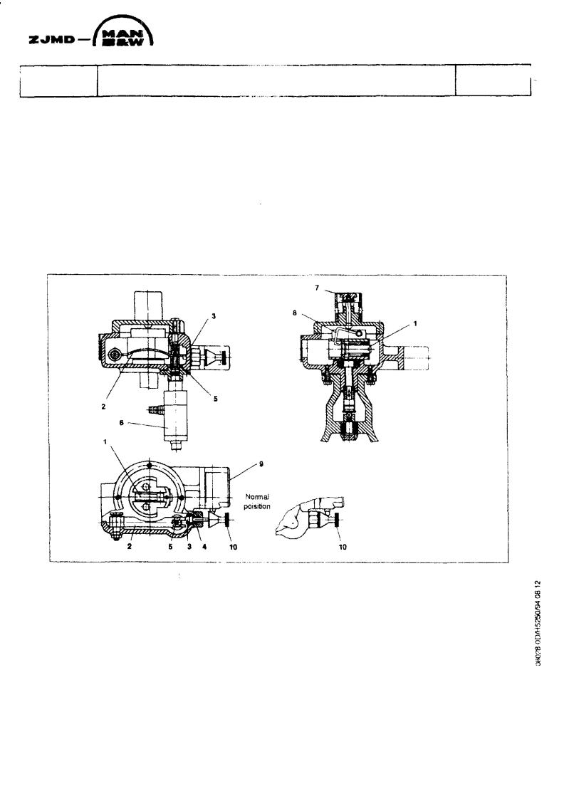
Mechanical Overspeed (SSH 81)
The engine is protected against overspeeding in the event of, for instance, governor failure by means of an overspeed trip.
The engine is equipped with a stopping device which starts to operate if the maximum permissible revolution number is exceeded.
The overspeed tripping device is fitted to the end cover of the lubricating oil pump and is driven through this pump.
Ifthepresettrippingspeedisexceeded,thespring-loadedflyweight(
and press down the arm (2).
The arm is locked in Its bottom position by the lock pin (3) which is pressed in by the spring (4).
At the same time the arm (2) presses down the spindle (5), and the pneumatic valve (6) opens, whereby compressed air will be led to the Lambda cylinder, see description 509.10, inwhichthe piston is pressed forward and, through the arm, turns the fuel pump regulating rod to STOP position, thereby the engine stops, the spring-loaded pull rod connection to the governor being compressed.
509.01 |
Control and Safety Systems |
|
Edition 01H |
||
|
||
L23/30H |
|
Description
Page 2 (2}
The engine can be stopped manually by pressing down the button (7), see fig. 1, which will activate the spring-loaded fly weight (1) through the lever (8).
If the overspeed has been activated the overspeed must be reset before the engine can be started Reset is done by means of the button (10).
The overspeed alarm (SAH 81) is activated by means of the micro switch (9).
Overspeed
activated
Fig 1. Mechanical overspeed(SSH 81)
1.Flyweight
2.Arm
3.Lock pin
4.Spring
5.Spindle
6.Pneumatic valve
7.Button
8.Lever
9.micro switch
10.Button
509.05 |
Instruments and Automatics |
Description |
Edition 01H |
Page 2 (3) |
|
|
|
|
|
|
|
L23/30H
Instrumentation
As standard the engine is supplied with the following instrumentation mounted local on the engine:
Thermometer |
TI 01 LT water - inlet air cooler |
|
Thermometer |
TI 02 LT water - outlet from air cooler |
|
Thermometer |
TI 03 LT water - outlet from lub. oil cooler |
|
Thermometer |
TI 10 HT fresh water - inlet to engine |
|
Thermometer |
TI 11 |
HT fresh water - outlet each cylinder |
Thermometer |
TI 20 |
Lubricating oil - inlet to cooler |
Thermometer |
TI 22 |
Lubricating oil - outlet from filter |
Thermometer |
TI 30 Charge air - inlet to cooler |
|
Thermometer |
TI 31 Charge air - outlet from cooler |
|
Thermometer |
TI 40 |
Fuel oil - inlet to engine |
Thermometer |
TI 60 Exhaust gas - outlet each cylinder |
|
Thermometer |
TI 61 |
Exhaust gas - outlet turbocharger |
The actual number of the instrumentation for the plant can be seen on the diagrams for the specific plant in the sections 512-513-514-515-516.
For code identification see 500.20.
Pressostates and Thermostates
The engine is supplied with a number of alarmand shut-down functions. The alarms shall via the alarm panel worn against an abnormal working condition, which can lead to break down and the shut-down functions shall stop the engine before a break down. I.e. a shut-down is "worse" than an alarm because a shut-down is given if the engine could be severe damage by running on these conditions.
As standard the engine is equipped with:
Shut-down Switches for
-too low lubricating oil pressure - inlet engine
-too high HT FW temperature - outlet engine
-too high engine speed (over speed)
Alarm Switches for
-leaking fuel oil
-too low lubricating oil pressure - inlet engine
-too low prelubricating oil pressure (level alarm)
-too high press. drop across lub. oil filter
-too high HT FW temperature - outlet engine
-too low starting air pressure - inlet engine
-too high engine speed (overspeed)
The actual number and type of the alarmand shutdown switches for the plant can be seen in the list "Engine Automatic part list" in this section.
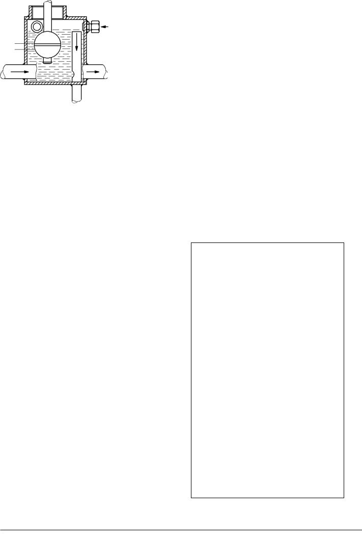
Leakage Alarm (LAH 42)
Waste and leak oil from the comparement, for the injection equipment, fuel valves, high-pressure pipes and engine feed pump (if mounted) is led to a fuel leakage alarm unit.
Normal leakage
C
B
Leak alarm Normal level
A
High level
Leakoil
Alarm
Normal
Waste oil outlet
08028-0D/H5250/94.08.12
Fig. 4. Fuel oil leakage alarm.
96.03 - ES0S

Description |
Instruments and Automatics |
509.05 |
Page 3 (3) |
Edition 01H |
|
|
|
|
|
|
|
The alarm unit consists of a box with a float switch for level monitoring, see fig. 4.
The supply fuel oil to the engine is led through the unit in order to keep heated up, thereby ensuring free drainage passage even for high-viscous waste/leak oil.
Under normal conditions there will always be a smaller amount of waste/leak oil from the comparement, this will be led out through the bore "A" in the pipe "B" as illustrated.
In case of a larger than normal leakage, the level in the box will rise and the level switch "C" will be activated. The larger amount of leak oil will be lead out through the top of the pipe "B".
L23/30H
Alarm for Prelubricating (LAL 25)
Alarm for missing prelubricating, when the engine is stopped is given by means of a level switch (LAL 25) mounted in the main lubricating oil pipe.
Alarm and Shut-down for Overspeed
When the mechanical overspeed is activated, see 509.01 fig. 2, a micro-switch will release the alarm for overspeed (SAH 81) and activate the shut-down solenoid in the governor.
The latter function is a back-up for the mechanical overspeed.
08028-0D/H5250/94.08.12
96.03 - ES0S

Description |
Lambda Controller |
509.10 |
Page 1 (2) |
Edition 09H |
|
|
|
|
|
|
|
Purpose
The purpose with the lambda controller is to prevent injection of more fuel in the combustion chamber than can be burned during a momentary load in-crease. This is carried out by controlling the relation between the fuel index and the charge air pressure.
The Lambda controller is also used as stop cylinder.
Advantages
The lambda controller has the following advantages:
-Reduction of visible smoke in case of sudden momentary load increases.
-Improved load ability.
-Less fouling of the engine's exhaust gas ways.
-Limitation of fuel oil index during starting procedure.
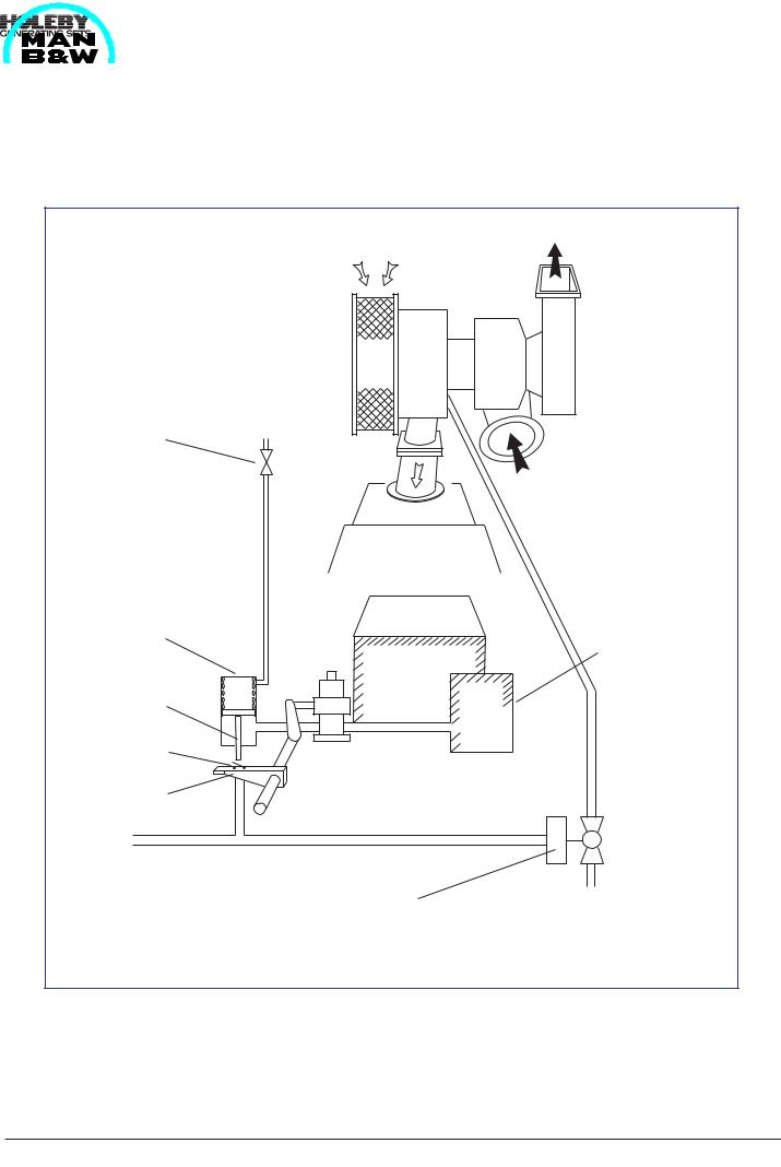
Principles for functioning
Figure 1 illustrates the controller's operation mode. In case of a momentary load increase, the regulating device will increase the index on the injection pumps and hereby the regulator arm (1) is turned, the switch
(2) will touch the piston arm (3) and be pushed downwards, whereby the electrical circuit will be closed.
L23/30H
Thus the solenoid valve (4) opens. The jet system is activated, the turbocharger accelerates and increases the charge air pressure, thereby pressing the piston
(3) backwards in the lambda cylinder (5). When the lambda ratio is satisfactory, the jet system will be deactivated.
At a 50% load change the system will be activated for about 3-8 seconds.
If the system is activated more than 10 seconds, the solenoid valve will be shut off and there will be a remote signal for "jet system failure".
Fuel oil limiting during start procedure
During the start procedure the lambda controller is used as an index limiter.
Hereby heavy smoke formation is prevented during start procedure and further the regulating device cannot over-react.
Air Consumption
At 50% step load the air consumption will be as follows:
Cyl. no. |
5 |
6 |
7 |
8 |
|
|
|
|
|
Nm3 |
0.70 |
0.84 |
0.98 |
1.12 |
|
|
|
|
|
08028-0D/H5250/94.08.12
04.15 - ES0-G
509.10 |
Lambda Controller |
Description |
Edition 09H |
Page 2 (2) |
|
|
|
|
|
|
|
L23/30H |
|
|
1.Regulating arm
2.Switch (Pick-up)
3.Piston
4.Solenoid valve
5.Lambda controller
6.Overspeed device
(mecanical activated 3/2 valve)
6
5
3
2
1
~
Charge air receiver
4 |
Engine's |
|
compression |
|
air system |
Fig 1 Lambda controller incl. start limitation
04.15 - ES0
Description |
Starting Box |
509.35 |
Page 1 (1) |
Edition 01H |
|
|
|
|
|
|
|
|
|
L23/30H |
08028-0D/H5250/94.08.12
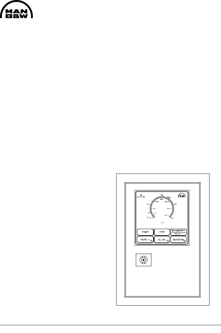
Description
The starting box is mounted on the engine's control side. On front of the box there are the following indications/pushbuttons:
-Indication of engine or turbocharger RPM
-Indication of electronic overspeed
-Pushbutton for "Manual Start"
-Pushbutton for "Manual Stop"
-Pushbutton for "Remote" *
-Pushbutton for "Local" *
-Pushbutton for "Blocking" *
-Pushbutton for change-over between engine and turbocharger RPM
*The function chosen is indicated in the pushbutton. See fig 1.
Manual Start
The engine can be started by means of the start button, but only if the button "Local" is activated.
The manual, local start is an electrical, pneumatic start, i.e. when activating the start button a solenoid valve opens for air to the air starter, thereby engaging the starter and starting the diesel engine. Throughout the starting cycle the start button must be activated.
The air starter is automatically disengaged when the diesel engine exceeds 140 RPM. If the start button is disengaged before the diesel engine has exceeded 140 RPM, further starting cycles are blocked, until 5 sec. after the engine is at standstill.
Remote Start
Remote start can only take place if the pushbutton for "Remote" is activated.
Manual Stop
The "Manual Stop" button is connected to the stop coil on the governor.
Blocking
If "Blocking" is activated, it is not possible to start the diesel engine.
Engine / Turbocharger RPM
By activating the "Engine RPM/TC RPM" button, the indication is changed.
Engine RPM indication is green light-emitting diodes and turbocharger RPM indication is red light-emitting diodes.
External Indications
There are output signals for engine RPM and
turbocharger RPM. |
|
|
|
|||
Engine: |
0 |
- |
1200 |
RPM |
~ |
4-20 mA |
TC: |
0 |
- |
60000 |
RPM |
~ |
4-20 mA |
The pushbuttons for "Remote", "Local" and "Blocking" have potential free switches for external indication.
All components in the starting box are wired to the built-on terminal box.
Fig 1. Starting box
94.26 - ES2S-G
Description |
Converter for Engineand Turbocharger RPM Signal |
509.40 |
Page 1 (1) |
Edition 01H |
|
|
|
|
|
|
|
08028-0D/H5250/94.08.12
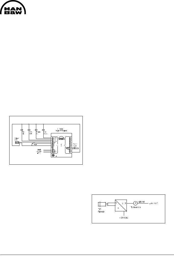
Engine RPM signal
For measuring the engine's RPM, a pick-up mounted on the engine is used giving a frequency depending on the RPM. To be able to show the engine's RPM on an analogue tachometer, the frequency signal is sent through an f/I converter (frequency/current converter), where the signal is transformed into a proportional 4-20 mA ~ 0-1200 RPM signal.
Further, the converter has following signals:
-overspeed
-engine run
-safe start
-tacho fail
Fig 1. Converter for engine RPM.
Overspeed
When the engine speed reach the setpoint for electronic overspeed the converter gives a shutdown signal and a alarm signal through a relay.
Engine run
When the engine speed reach 710 RPM or 200 RPM + 10 seconds the converter gives a "engine run" signal.
The engine run signal will be deactivated when the speed is 640 RPM. If the engine speed haven't been over 710 RPM the signal will be deactivated at 200 RPM.
L23/30H
The "engine run" signals will be given through a relay. One for synchronizing and one for start/stop of pre. lub. oil pump or alarm blocking at start/stop.
Safe start
When the safe start signal is activated the engine can start. When the engine reach 140 RPM the air starter will be shut-off.
Further, the safe start signal is a blocking function for the air starter during rotation.
Tacho fail
The tacho fail signal will be on when everything is normal. If the pick-up or the converter fails the signal will be deactivated. E.g. if there is power supply failure.
The converter for engine RPM signal is mounted in the terminal box on the engine.
Turbocharger RPM signal
For measuring the turbocharger RPM, a pick-up mounted on the engine is used giving a frequency depending on the RPM. To be able to show the turbocharger's RPM on an analogue tachometer, the frequency signal is sent through a f/I converter (frequency/current converter), where the signal is transferred into a proportional 4-20 mA ~ 0-60000 RPM.
Fig 2. Converter for TC RPM.
The converter is mounted in the terminal box on engine.
96.30 - ES2S-G

Working Card |
Functional Test and Adjustment of Safety, |
509-01.00 |
Page 1 (2) |
Alarm and Monitoring Equipment |
Edition 01H |
|
|
L23/30H |
08028-0D/H5250/94.08.12
Safety precautions |
Special tools |
|
|
Stopped engine |
Plate No |
Item No |
Note. |
Shut-off starting air |
|
|
|
Shut-off cooling water |
See Related Procedure |
||
Shut-off fuel oil |
|
|
|
Shut-off cooling oil |
|
|
|
Stopped lub. oil circul. |
|
|
|
Description |
|
|
|
Function test and adjustment of safety, alarm and |
Hand tools |
|
|
monitoring equipment. |
|
|
|
|
See Related Procedure |
|
|
Starting position |
|
|
|
Related procedure
Overspeed trip |
509-01.05 |
Pressostate |
509-05.00 |
Thermostate |
509-05.01 |
Level switch (LAL 25) |
509-05.02 |
Analog pressure transmitter |
509-05.03 |
Analog temperature transmitter |
509-05.04 |
Man power |
|
|
Replacement and wearing parts |
||
Working time |
: |
hours |
Plate No |
Item No |
Qty. / |
Capacity |
: |
man |
|
|
|
Data |
|
|
|
|
|
Data for pressure and tolerance |
(Page 500.35) |
|
|
||
Data for torque moment |
|
(Page 500.40) |
|
|
|
Declaration of weight |
|
(Page 500.45) |
|
|
|
03.32 - ES0

509-01.00 |
Functional Test and Adjustment of Safety, |
Working Card |
Edition 01H |
Alarm and Monitoring Equipment |
Page 2 (2) |
|
||
L23/30H |
|
|
Maintenance of monitoring and safety systems
One of the most important parameters in the preventive work is that the alarm system as well as the shutdown and overspeed devices are functioning 100%.
If some of these functions are out of operation, they have to be repaired immediately. If this is not possible because of the present working situation, the engine has to be under constant observation until it can be stopped.
It is recommended that all functions are tested every three months according to the mentioned working cards.
The extent of the alarm and safety functions is variable from plant to plant.
For check of these functions use the working cards mentioned under related procedure on page 1.
Alarm System
It is important that all alarms lead to prompt investigation and remedy of the error.
No alarm is insignificant. It is therefore important that all engine crew members are
familiar with and well trained in the use and importance of the alarm system.
The most serious alarms are equipped with slowdown and/or shutdown functions.
08028-0D/H5250/94.08.12
03.32 - ES0