

Phedotikov / 1 / FreeEnergy_27.01.08 / Схемотехнические / Генератор Tesla Switch / Nikola Tesla’s 4-Battery Switch
.pdf3. Energy can be returned to a battery power source by its own load
Tesla 4-battery system, Bedini 3-battery system, Ron Cole’s 1-battery system
Nikola Tesla’s 4-Battery Switch
Pupils in school are taught that if a bulb is connected across a battery, a current flows from the battery, through the bulb and back to the battery. This current causes the bulb to light, and after a time, the battery runs down and is no longer able to light the bulb. This is completely correct.
However, this teaching gives the wrong impression. It implies that the “work” done in lighting the bulb, uses up the electricity coming from the battery and that the battery somehow has a store of electricity, something like the sand in an hourglass or egg-timer, which when it runs out will no longer be able to light the bulb. Interestingly, those same teachers will show the correct picture of the circuit, drawing it like this:
You will notice that the 1-amp current flowing out of the bulb is exactly the same as the 1-amp current flowing into the bulb. Exactly the same amount of current comes out of the bulb as the current which flows into the bulb. So, how much current is “used up” in doing the work of lighting the bulb? Answer: None. Energy is never destroyed, the most that can happen to it is that it gets converted from one form to another.
So why does the battery end up not being able to light the bulb any more? Well, that is a feature of the way that batteries operate. If the current flow is in one direction, then the battery gets charged up, and if it is in the other direction, then the battery gets discharged:
The battery getting run down, has nothing to do with the current flowing through the bulb, the battery would get run down if the bulb were left out of the circuit. The useful “work” of creating light by having the current flow through the bulb, does not “use up” any current, and more importantly, it does not “use up” any energy. Energy cannot be “used up” - it just gets transformed from one form to another. This is difficult to understand as we have been taught that we have to keep buying energy from the electricity supply companies to power our equipment. The false idea is that we buy the energy, and it then gets “used up” in the equipment, so we have to buy some more to keep the equipment going. We accept it because that’s what we were taught. It isn’t true.
The current flowing through the bulb can be arranged to be a charging current for another battery. It can both light the bulb and charge another battery without needing any extra current:
Here, the circuit is powered by battery 1 as before, but this time the current goes on to charge battery 2. Yes, battery 1 gets discharged just as before, but the plus side is that battery 2 is getting charged up all the time. The
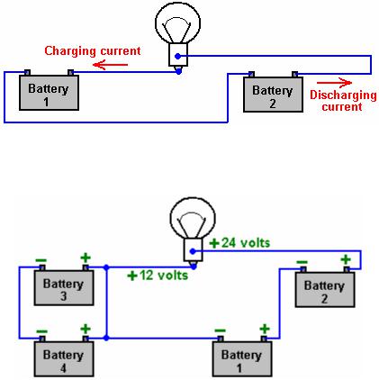
final step is to swap the batteries over:
And now, the newly charged battery 2 lights the bulb and charges up battery 1 again. Seem impossible? Well it isn’t. Nikola Tesla demonstrates this with his “4-battery switch” system where he chooses to use four identical batteries to implement this circuit:
With 12-volt batteries as shown here, the bulb has the same 12 volts across it as it would have had with the single battery shown in the first diagram, as batteries 1 and 2 are wired “in series” to give 24 volts, while batteries 3 and 4 are wired “in parallel” to give 12 volts. Tesla arranged his circuit to swap the batteries over with 1 and 2 taking the place of 3 and 4. He chose to do it in a slightly different way and he swapped the batteries over hundreds of times per second.
The Weird stuff:
There is another important factor involved in battery-charging circuits to be used with normal lead-acid batteries and that is the practical detail of the materials involved. The charging process in this switching circuit is carried out by electrons flowing down the connecting wire and into the battery. The electrons flowing along the outer surface of the wire, move very rapidly indeed. The main current inside the battery is carried by the charged ions inside the lead plates inside the battery. These ions are hundreds of thousands of times heavier than the electrons. This doesn’t matter at all once the ions get moving, but in the initial split second before the ions get going, the incoming electrons pile up like in a traffic jam tail-back. This pile-up of electrons pushes up the voltage on the terminal of the battery, well above the nominal battery voltage, and so the charging starts off with a high-voltage, high-current pulse into the battery.
This is not normally noticed when using a standard mains-powered battery charger, as switch-on only occurs once during the whole charging process. In the Tesla switch shown here, and in the Bedini circuits shown earlier, this is not the case. The circuit takes advantage of this difference in momentum between the electrons and the lead ions, and uses it repeatedly to great advantage. The technique is to use very short duration pulses all the time. If the pulses are short enough, the voltage and current drive into the receiving battery is far greater than a quick glance at the circuit would suggest. This is not magic, just common-sense characteristics of the materials being used in this circuit.
A person unfamiliar with these systems, seeing John Bedini’s many advanced circuits for the first time, might get the impression that they are just crude, roughly-built circuits. Nothing could be further from the truth. John often uses mechanical switching because it gives very sharp switch-on and switch-off times. John is a complete master of this circuitry and knows exactly what he is doing
The Electrodyne Corporation tested the Tesla 4-battery circuit over a period of three years. They found that at the
end of that period, the batteries did not show any unusual deterioration. The batteries used were ordinary leadacid batteries. The system operated lights, heaters, television sets, small motors and a 30-horsepower electric motor. If the batteries were run down to a low level and then the circuit switch on with a load, the recharging of the batteries took place in under one minute. No heating was experienced during this rapid charging. Heat was only produced during discharge cycles. If left undisturbed, each battery would charge up to nearly 36 volts. Control circuitry was developed to prevent this over-charging. They used mechanical switching and stated that below 100 Hz there was not much advantage with the circuit and above 800 Hz it could be dangerous.
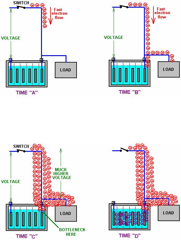
They didn’t mention why they consider that higher rates of switching could be dangerous. If we consider what exactly is happening, perhaps we can work out why they said that. The charging situation is like this:
At Time “A” the switch closes, connecting a voltage source (battery, charged capacitor, or whatever) to a lead-acid battery. Electrons start flowing down the outside of the connecting wire. Being very light and having little obstruction, they move very fast indeed (the electrons inside the wire only move a few inches per hour as getting through the wire is difficult). All goes well until Time “B” when the leading electrons reach the lead plates inside the battery. Here, they have a problem, because the current flow through the plates is carried by lead ions. Lead ions are very good at carrying current, but it takes them a split second to get going due to their weight. That split second is critical and it opens the door to free-energy. In that split second, the electrons pile up because they are still arriving down the wire at very high speed. So, at Time “C” they have built up into a large body of electrons.
This large body of electrons has the same effect as if there had been a sudden connection to a much higher
voltage source capable of supplying a much higher current. This situation only lasts for a very short time, but it has three very important effects. Firstly, at Time “D”, it drives a much larger current into the battery than could reasonably expected from the original voltage source. Secondly, this effect alters the Zero-Point Energy field (the space-time continuum) in which the circuit is located, causing extra energy to flow into the circuit from the outside environment. This is a bit like sunshine generating current flow in an electric solar panel, but instead of visible sunshine, the energy flow is not visible to us. Thirdly, the excess energy flows into the battery, charging it much more than would be expected, and at the same time, some of the excess energy flows into the load, powering it as well. The load could be a lamp, a motor, an inverter, a pump, a drill, or whatever.
So, excess energy is collected from the environment and used to both charge the battery and at the same time, perform useful work. The old saying “you can’t have your cake and eat it” just does not hold in this situation as that is exactly what happens. Instead of the battery being run down from powering the load, the load gets powered and the battery gets charged up at the same time. This is why, with this system, a discharged battery can be used to apparently run a motor. It works because the plates in the discharged battery are made of lead which forms a bottleneck for the electron flow, causing the environment to charge the battery and run the load at the same time. That is why you get what looks like the magical effect of a discharged battery appearing to power a load. In passing, the more discharged the battery, the faster it charges as the environment adjusts automatically to the situation and feeds greater power into a flat battery. The environment has unlimited power available for use. John Bedini who is expert in this field has had motors running continuously for three or more years with the battery never running down and the motor doing useful work all the time. Great battery? No, - great environment !!
For the vital build up of excess electrons to take place, the switch closure has to be very sudden and very effective. A thyristor or “SCR” is suitable for this as once it is started, it switches on rapidly and fully. Sound good so far? This is only the start. I suggest that the Tesla 4-battery switch circuit operated in the 100 Hz to 800 Hz region operates in this way.
This situation can be further enhanced by suddenly cutting off the electron flow from the original voltage source while the excess electron pile-up is still in place. This causes a sudden (very brief) further surge in the excess power, building up the voltage and current even further and increasing the battery charging and load powering drive.
An even greater effect can be had if the next, short, sharp pulse is applied to the battery/load combination, just before the effect from the last pulse dies away. I suggest that this is the situation which the Electrodyne Corporation people encountered when the pulse rate went over the 800 Hz rate. I suggest that it is not so much a case that the battery and load could not take the power, but more a case that the components which they were using were not rated high enough to carry that level of power. They do mention that if they went further, that they found that some of their circuit components started failing through not having high enough ratings (notice that the output capacitors are rated at 100 volts which is eight times the nominal battery voltage). This was hardly a problem, considering that they had 12-volt batteries operating happily at 36-volts if they wanted that. They ended up building circuitry to hold the voltages down to a convenient level.
To summarise the situation. The Tesla 4-battery switch appears to do the impossible through:
1.Catching the current coming out of the load and using it to charge another battery instead of wasting it.
2.Providing very short, sharp, and rapid switching pulses which exploit the momentum of the lead-ions current flow.
3.Pulling extra energy in from the local environment to both charge the batteries and power the load at the same time
This leaves aside the possibility of two further gains available through very precise timing of the switching pulses (mainly to make the power available more easily and cheaply handled). So, it should be borne in mind that the practical issues involved in getting this circuit operating effectively are primarily about very fast, clean and welltimed switching. Stranded, high-current rated wire will be helpful in getting the draw of excess energy into the circuit.
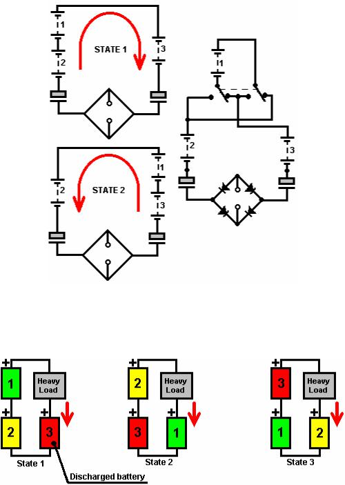
Here is the switching sequence for the Tesla 4-battery switch system:
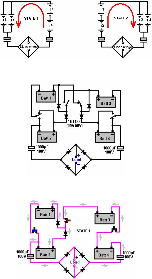
As you can see, this is essentially the same circuit with batteries 1 and 2 swapping over with batteries 3 and 4. But he has added in two capacitors and a diode bridge of four diodes to power the “load” (bulb, motor, TV or whatever). His circuit diagram is usually shown like this:
Here, Tesla has used four diodes to simplify the switching and reduce it to two On/Off switches plus two changeover switches. Alternatively, six On/Off switches can be used. As the diagram is a little difficult to follow when shown like that, the following diagrams may help by showing the current flow during the two states:
Here, batteries 1 and 2 are wired across each other while batteries 3 and 4 are wired in series. This needs three On/Off switches and the two diodes are inserted so that the plus terminal of battery 1 is not permanently connected to the plus terminal of battery 2, because in State 2, that connection must not be made.
The State 2 wiring is almost identical, requiring another three On/Off switches and two diodes to avoid a permanent link between the plus terminals of batteries 3 and 4.
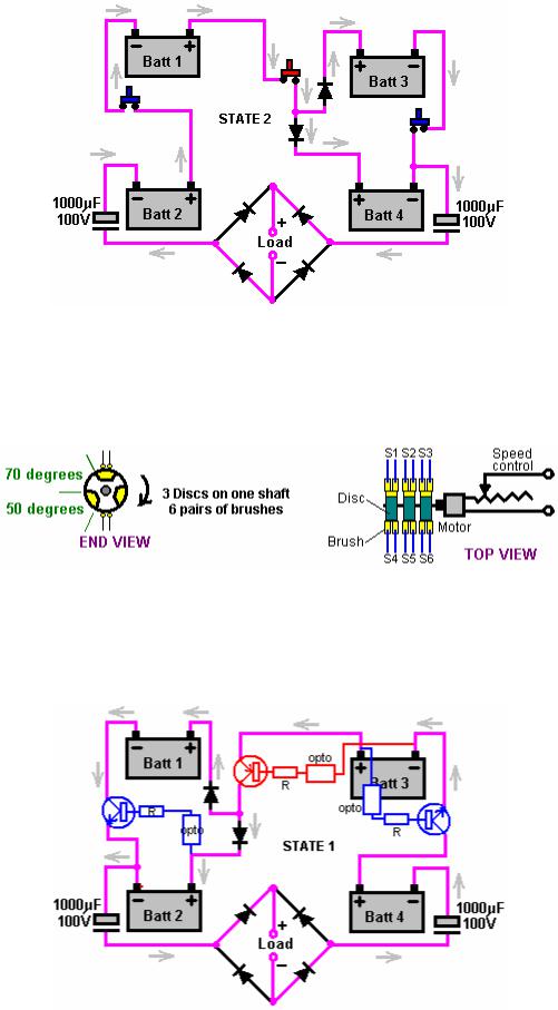
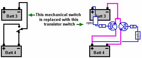
It has been suggested that a simple way to make the six high-speed On/Off switches is to use three discs mounted on the shaft of a motor as shown here:
The three rotors are insulated from each other and the conducting sectors are aligned, as are the brushes. The arrangement gives a mechanical switching such that when the upper brushes are short-circuited together, the lower brushes are open-circuit. Obviously, it is vital that at no point in the rotation are the two sets of brushes connected at the same time, i.e. there needs to be a “Break Before Make” switching arrangement. Many people prefer solid-state switching to mechanical switching and so it should be possible to arrange this. Here is a suggestion for doing that:

Each of the three mechanical switches are replaced with a transistor - one PNP type and two NPN type. These need to be able to handle 30 amps, so although not shown here, they will probably be Darlington pairs with the low gain of the high-power transistor being boosted by the additional gain of a driver transistor, perhaps something like a 2N3055 / 2N2222A combination. The transistor base current comes via a limiting resistor fed from an appropriate battery terminal a fixed 12 volts above it. The switching is controlled via an opto-isolator and the three opto isolators which switch together (shown above) are driven from one side of an astable multivibrator (probably an NE555 chip connected for this). The other three opto-isolators needed to perform the switching for State 2, will be Off during State 1, so they will be driven by the inverted version of the same NE555 signal. This ensures that three will be On and three will be Off at all times.
The suggested transistor switching for the State 2 situation is shown above. This is just an attempt to perform the switching with the most simple components available.
The mechanical changeover switch can be replaced with transistors:
and
The hope is that the opto-isolators can switch on and off fast enough to form an effective tap to the zero-point energy field which is everywhere around us. If they can, then it is likely that additional circuitry will be needed to cut off the extra power when the energy in the batteries rises to the point where it could endanger the equipment which it is powering.
Circuitry of this type is very easy to design and build, and the electronics tutorial which forms part of this set of documents shows the principles which can be used for this. My inclination would be to have the control circuitry kick in at fourteen or fifteen volts and drop out again when the battery voltage drops back to 12.5 volts or so.
This Tesla circuit is said to be able to power its load indefinitely. It is also said that if one of the batteries is fully discharged, or nearly fully discharged, then putting it in any of the four positions returns it to full charge within one minute.
The connecting wires should be at least 30 Amp current carrying capacity and the individual diodes and the diode bridge are rated at 35 Amps 50 Volts. The circuit is intended for use with lead/acid batteries but John Bedini has successfully used rechargeable NiCad batteries in one implementation of this circuit.
This circuit was invented by Nikola Tesla who was an intuitive genius, and shown to his close friend Ronald Brandt, who in turn disclosed it in 1983 to John Bedini. John provided the details in a paper which he presented to the Tesla Centennial Symposium in 1984. At the symposium, John showed his solid state implementation of the circuit powered by NiCad batteries. During a continuous twenty-four hour period, John’s device powered a load and at the end of the period, the batteries were shown to be fully charged.
In passing, the term “load” just means some piece of useful equipment which we might want to operate, say, a light, a fan, a heater, a drill, or whatever. The circuit described provides about 12 volts as the output, so mains equipment would be operated using a standard, commercial “inverter” which converts this low DC voltage to normal mains AC voltage capable of powering TV sets, DVD recorders, or whatever.
There have been several different solid-state versions of the Tesla 4-battery switch. One designed by John Bedini is shown here:
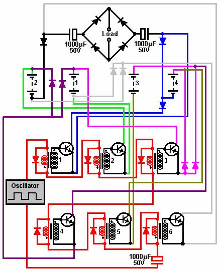
Here, six 2N3055 transistors (60V, 15A, gain 20 to 70) are powered on and off via six audio transformers (Radio Shack #273-1380 transformers are suggested). The 8 ohm primaries are wired in series and driven by a square wave generator through a large capacitor. This circuit is shown in red. When the square wave is positive, the upper three transformers (numbers 1 to 3) have their primaries loaded by a forward-biased diode which will hold the voltage across them to a maximum of some 0.7 Volts thus limiting their operation. The other three transformers (numbers 4 to 6) have the diodes across their primaries biased off for a positive voltage and so have little effect on the pulse applied to their windings. The operation of the two groups of transformers is reversed for the negative pulse from the square wave generator. The diodes across the transformers are 1N4148 (100V, 300 mA, high speed) and the others 1N1183 (50V, 40A).
My concern with this arrangement is that the secondaries are 1000 ohm windings which gives a nominal step-up ratio of 125. If 0.7 Volts is applied as a pulse to the primary, theoretically, 87.5 volts would be generated at the secondary if it were open-circuit. Obviously, this will not happen as the base/emitter junction of the 2N3055 transistor loads the secondary heavily. However, in my opinion, there is the potential for at least partial switching on of the transistors which are supposed to be biased hard off. I would therefore suggest that if this circuit is used, that the output from the square wave generator be taken through two separate drivers to the two chains of three transformer primaries. That way, it can be ensured that the second set of transformer primaries is receiving zero volts when they are supposed to be off.
I have been told by one experimenter that considerable power gains can be had from just using manually operated switches, and swapping the batteries over with long time periods between switch changes. This will just be using the collection of the current which has just flowed through the load.
Bedini 3-battery system. John Bedini has pointed out that the electrical effect of the Tesla 4 battery switch can be reproduced with just three batteries:
However, in the above arrangement, the battery marked ‘1’ never has its flow direction reversed. This may not be critical as the energy being provided is being taken from the zero-point energy field and not the batteries.
The block diagram used by John when he was designing his circuit was:
This is a much more difficult switching circuit to construct. If one battery, say ‘3’ in the diagram above, is fully discharged when placed in the circuit, it is said that it gets fully recharged in less than one minute.
If mechanical switching were being used (which it isn’t as it would be much too slow), the connections could be like this for state 1: