

Impedance matching role in resonance related to the rv.
Within an oscillating system with low impedance hi Q you need nearly no energy to fill the cap. If you are simply charging a cap from a DC source over an ohm resistance (wire) you will "loose" half of the energy due the resistance’s if you loose an energy amount of 1 in your dc source, the resistor got 0.5 and the cap also 0.5.
BUT:
Within the RV you have an oscillating (resonance) system due the cap and the coils within the RV prime mover. You have also an AC source.
Due the AC you get your rotor to spin and your LC to oscillation. The inner LC-oscillation works "against" the <current flow> which depletes your AC source. That is noticed as "High Impedance" from your source.->Low current from source -> low energy consumed.
BUT: Due the inner oscillation (which is at high Q) you have high currents within the LC and strong currents through the inner coils and strong magnetic fields, which are driving the rotor. The only energy you need from your AC source is the energy to compensate the losses within the LC (for unloaded motor).
Look at the RV prime mover schematic and identify the LC (one cap (start or run) and 2 coils). Here being c1 and c2, the coils are referenced by L1, L2 and L3.

Imagine what is going on while the LC oscillates with the same frequency as your AC source. its not all 100% correct, as you need to consider what does occur due to the motor loading, but should make the main principle a bit plainer.
Resonance continued.
Also Stochastic (Being or having a random variable) resonance is a form of random noise which it also utilized in RV mode.
Stochastic resonance
The basics of stochastic resonance describe how weak signals are amplified by applying random noise. It is a phenomenon in physics where a weak signal to faint to be detected can be amplified by the addition of random noise. It is generally applied in the field of radio and related studies. The basics are as a signal passes a medium it is amplified, and that is what over unity is all about.-consolidated knowledge
Here is a text book definition which from the above paragraph might help you visualize it more.
Stochastic resonance occurs when the signal-to-noise ratio of a nonlinear device is maximized for a moderate value of noise intensity. It often occurs in excitable systems with sub threshold inputs. For lower noise intensities, the signal does not cause the device to cross threshold, so little signal is passed through it. For large noise intensities, the output is dominated by the noise, also leading to a low signal-to-noise ratio. For moderate intensities, the noise allows the signal to reach threshold, but the noise intensity is not so large as to swamp it. Thus, a plot of signal-to-noise ratio as a function of noise intensity shows an upside-down "U" shape
The phrase signal-to-noise ratio, often abbreviated SNR or S/N, is an engineering term for the ratio between the magnitude of a signal (meaningful information) and the magnitude of background noise. Stochastic resonance occurs when the signal-to-noise ratio of a nonlinear device is maximized for a moderate value of noise intensity.
Often the signals being compared are electromagnetic in nature, though it is also possible to apply the term to sound and light stimuli.
RADIANT ENERGY
Now we have come to another important factor. And that is another part of a process that is enabling the radiant energy that’s transformed by the RV alternator.
radiant energy 1. Any form of energy emitted by a source and propagated through space as an electromagnetic disturbance. Included are radio waves, infrared, visible light, ultraviolet, X rays, and gamma rays. 2. Electromagnetic disturbances at infrared and shorter wavelengths.
Quote- the RE (Radiant Energy) phenomenon occurs when a RLC circuit has the appropriate impedance, and is in resonance when a standing wave is created. Because of the L (inductor) and C (capacitor), there is a 90°phase shift between V (voltage) and I (current in Ampere). –end quote. Reference RE-OU 5.1
In radiant energy effects as in resonance there are regions of standing wave energy called Nodes. These nodes are either a 0 current and max voltage regions or 0 voltage and max current regions as alike measured in 1:1 VRSW RF antenna dipole
STANDING WAVES
Note that this is relative for the RADIANT ENERGY ALTERNATOR LC part where we want hi Q (which stands for the quality of the effective resistance in an inductor, or capacitance of a capacitor being its reactive power) all the time as a Radiant energy source.
Before we go in depth of text book standing wave descriptions here is a reference directly quoted from hector .
The radiant energy is formed by a Standing wave , as per RF (radio frequency) (explained more below) resulting from pure resonance were the current AC node is separated from a VOLTAGE radiating node being polarized (directed) as standing wave regions.
This is where one is node & the other anti node. In one we have 0 point region (electron Vacuum) in other we have aether (space) density accumulation as compression tensor (string). can be also defines as HOT ionizing and cold anti ion region.
Note:
NODE:
A point defined within a sine wave be it voltage or current were such potential manifest in a physical object as antenna section , dipole ,LC , R or any circuit component or structure for further detail Look for Antenna design, resonance. (explained below)
STANDING WAVE
a wave oscillating contained within a predetermined space or structure containing current node and voltage node. Visual examples of both terms are described below.
Hector describes that the standing wave relation happens from the Phase shifting from 90 to 0 or 180 being the case voltage or current and having a core latching effect ( similar to
Floyds VTA device ) if applied to energy transform and OU. This is analogous In an antenna element of RF design where you have an antenna multiplication factor each phase can become a simile of such.
Prime mover is one aspect and the Alternator is another. In the 2 you find levels of EM (electro magnetic) amplification. in Prime mover you have EXTRA phased element creating 3 phases. In Alternator you have 1 or 3 LCs (inductor/capacitor) reverse induction driven. In the 2 you have power amplification manifested , the need is to enhance that amplification FACTOR and understand it .
To help explain this by an introduction to the principles the flowing was taking from a navy manual on radio antenna behaviour. This will give a visual and detailed description of standing waves and the RF principles relating to the LC behaviour aforementioned.
Note view the graph illustration bellow.
if an alternating current is applied at the A end of the length of wire from A to B, the wave will travel along the wire until it reaches the B end. Since the B end is free, an open circuit exists and the wave cannot travel farther. This is a point of high impedance. The wave bounces back (reflects) from this point of high impedance and travels toward the starting point, where it is again reflected. The energy of the wave would be gradually dissipated by the resistance of the wire of this back-and-forth motion (oscillation); however, each time it reaches the starting point, the wave is reinforced by an amount
sufficient to replace the energy lost.
This results in continuous oscillations of energy along the wire and a high voltage at the A end of the wire. These oscillations are applied to the antenna at a rate equal to the frequency of the RF voltage.
Look at the current and voltage (charge) distribution on the antenna in figure 4-6. A maximum movement of electrons is in the center of the antenna at all times; therefore, the center of the antenna is at a low impedance. This condition is called a STANDING WAVE of current. The points of high current and high voltage are known as current and voltage LOOPS. The points of minimum current and minimum voltage are known as current and voltage NODES. View A shows a current loop and current nodes.
View B shows voltage loops and a voltage node. View C shows the resultant voltage and current loops and nodes. The presence of standing waves describes the condition of resonance in an antenna.
At resonance the waves travel back and forth in the antenna reinforcing each other and the electromagnetic waves are transmitted into space at maximum radiation. When the antenna is not at resonance, the waves tend to cancel each other and
lose energy in the form of heat.

Standing waves of voltage and current on an antenna.
radio frequency Abbreviation, RF. 1. Consisting of, or pertaining to, alternating currents at frequencies above about 9 kHz (the lowest allocated radio communications frequency). 2. Consisting of, or pertaining to, electromagnetic fields whose wavelengths are longer than those of infrared, but shorter than about 33 kilometers (corresponding to a frequency of 9 kHz). Also see RADIO SPECTRUM.
A standing 60hz wave (explained below) is vary long 3000000meters/60hz.
RF is determined by the angle of current and VOLTAGE (0) power factor 90 deg angle relation when current 0 voltage is maximal when voltage is 0 current is maximal in a PERFECTLY resonant LC. In 3 PHASE this can manifest within 45 to 90 degrees angle being differential the phase or angle of rotation relative as POWER factor figure (What differentiates it from power line AC) any signal with a 0 power factor figure is RF (Radiant) energy. SCOPE measurement is current versus voltage angle. http://www.ibiblio.org/obp/electricCircuits/AC/AC_6.html
Reference is contained in chapter 11 This POWER is in the RV ALTERNATOR section. The Prime mover of the RV is Broad banded signal NON RF potential that TENDS to RESONATE as LOADED (as in coupled to the alternator) whilst maintaining a 120 Degree angle of rotation within A,B,C phases being generated. The relation is SEMI resonant ,if not full resonant as a variable within a set of parameters.
The PM (prime mover) is a parallel resonant circuit configuration. When properly tuned, it should have a PF of as close to 1 as you can get. A PF of 1 is when the reactive components C&L cancel each others impedance and the apparent power = the true power. In a parallel resonant circuit the impedance as seen from the source goes to a high level (PM unloaded). When the PM is loaded more true power is dissipated so the impedance goes down.
With the PM under load you have to retune the C box for best PF (closest to 1). For the alt circuit we are dealing with a series resonant circuit configuration. In a series resonant circuit the source sees minimum impedance at resonance. So from hectors definition of RF =Radiant energy (when PF = 0,Xl=Xc & R=0) one would have the capacitive and inductive canceling each other out and maximum current would flow in the series resonant circuit. Since we will only be able to effectively tune the alt to semi resonance the object would be to tune the alt cross cap for a PF = as close to 0 as we can achieve.
What is done electrically with RV alternator is to spin the rotor squirrel cage (explained further below) (Reverse Inductor) inside a 3PH LC oscillator tank circuit where the effect is similar to the effect you can do by stroking a wet finger in a fine grass cup. One wave mounts to the other with the acoustic simile being magnetic multiplication factor
The above analogy of the waves mounting the others describes the principles aforementioned, being stochastic resonance, where electrons are accelerated in an oscillation inside virtual wall.
In RV ALTERNATOR at RESONANCE the 60CPS turn into ELF RF RADIANT
ENERGY sine wave. Elf is an acronym for extremely low frequency. A Magnet vibrates strongly as its approached to active LC wire (alternator) while in RV prime mover input wire is minimal.
You may use a magnet to detect this or as You have 2 different impedances interacting , one bands passes other filters , you need a specially modified Vector scope to see the signal in real-time 4D in a given timeframe Or use 4 channel scope in combination with audio spectroscope.
The standing wave can create regions of current and voltage called NODES and these can create secondary waves were the NODES shift (scroll ) within the resonant media . They can be higher or lower in frequency this waves can trap and transform other type of energy " Stochastic Resonance "amplification or OU transformation.


More Text book standing wave descriptions
A standing wave, also known as a stationary wave, is a wave (form) that remains in a constant position. This phenomenon can occur because the medium is moving in the opposite direction to the wave, or it can arise in a stationary medium as a result of interference between two waves traveling in opposite directions.
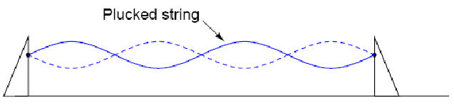
Standing waves are quite abundant in the physical world. Consider a string or rope, shaken at one end, and tied down at the other (only one half-cycle of hand motion shown, moving downward)

Both the nodes (points of little or no vibration near the hand) and the antinodes (points of maximum vibration top part and bottom of the middle) remain fixed along the length of the string or rope.
The effect is most pronounced when the free end is shaken at just the right frequency. Plucked strings exhibit the same "standing wave" behavior, with "nodes" of maximum and minimum vibration along their length. The major difference between a plucked string and a shaken string is that the plucked string supplies its own "correct" frequency of vibration to maximize the standing-wave effect:
Another example of a standing wave is where the wind hits the mountains (a very atmospheric and prolific experience) and the wind rises up as a result. This is another example of a standing wave. Some thing which hawks use to float upon the sky effortlessly.
The modes of vibration associated with resonance in extended objects like strings and air columns have characteristic patterns called standing waves. These standing wave modes arise from the combination of reflection and interference such that the reflected waves interfere constructively with the incident waves. An important part of the condition for this constructive interference for stretched strings is the fact that the waves change phase upon reflection from a fixed end. Under these conditions, the medium appears to vibrate in segments or regions and the fact that these vibrations are made up of traveling waves is not apparent - hence the term "standing wave".

The behavior of the waves at the points of minimum and maximum vibrations (nodes and antinodes) contributes to the constructive interference which forms the resonant standing waves.
As an example of the second type, a standing wave in a transmission line is a wave in which the distribution of current, voltage, or field strength is formed by the superposition of two waves propagating in opposite directions. The effect is a series of nodes (minima) and anti-nodes (maxima) at fixed points along the transmission line. Such a standing wave may be formed when a wave is transmitted into one end of a transmission line and is reflected from the other end by an impedance mismatch, i.e., discontinuity, such as an open or a short.
Transmission lines support standing waves, and force these waves to possess nodes and
Antinodes according to the type of termination impedance at the load end, they also exhibit resonance at frequencies determined by physical length and propagation velocity. Transmission line resonance, though, is a bit more complex than resonance of strings or of air in tubes, because we must consider both voltage waves and current waves.
Standing waves are waves of voltage and current which do not propagate (i.e. they are stationary), but are the result of interference between incident and reflected waves along a transmission line. Or if voltage and current hit a position if interference then a standing wave is reflected or created.
Logarithmic gain (1.618) within resonance from the ambient
The idea is that M field logarithmically charges C upon influencing inductance and core (if any) . logarithmic gain is 1.618 as defined optically by a cornu spiral.

a 4 D projection 72 degrees offset into "other plane" or Phase and virtual relative energy state. (physical model proves it ) RV alternator shows phenomena.
The theoretic optimal is 1.618 , that is the logarithmic energy gain from the ambient noise (thermal to electron transformation) as a basic figure . Energy from ambient being pumped into Coil by PM field as VAR translated to a CHARGE within a capacitor element as a final JOULE per second energy exceeding input .. (average ) for true Over unity transformation. Please refer to the ZPE theory at the end of this compilation for reference/understanding to the following statement(s).
The true definition of ZPE ( ZERO VOLTAGE ) ZERO POINT. Be it Current node or VOLTAGE node in RF (radio frequency) there is always a ZERO point reference were the logarithmic amplification projects in a spiral from 3d to 4D horizontal from vertical at 90degrees within a time space cone of 72 degrees scalar projection. Which is a Way of crudely defining a Cornu spiral within optical slit were amplification from ambient energy occurs. Refer to stochastic resonance phenomena . Hector also recommends to study the ARRL radio antenna manual as a basic introductory to radio frequency as the ‘behaviour’ is easily visualized and understood through those RF principles. Cold electricity is no other thing than RF (resonance) vectored in Nodes to attain OU (over unity) effects.
Power factor and power factor correction.
In power transmission and distribution, alternating current power is distinguished into three different types: real power (P), measured in watts (W); apparent power (S), measured in volt-amperes (VA); and reactive power (Q), measured in volt-amperes reactive (VAr).
Power dissipated by a load is referred to as true power. True power is symbolized by the letter P and is measured in the unit of Watts. (never mind watts)
Power merely absorbed and returned in load due to its reactive properties is referred to as reactive power. Reactive power is symbolized by the letter Q and is measured in the unit of Volt-Amps-Reactive
Total power in an AC circuit, both dissipated and absorbed/returned is referred to as apparent power. Apparent power is symbolized by the letter S and is measured in the unit of Volt-Amps (VA).
The power factor is determined by the type of loads connected to the power system. These can be
-
Resistive
-
Inductive
-
Capacitive
If a purely resistive load (like the light bulb) is connected to a power supply, the power factor will be unity (1) and only real power will flow.
Inductive loads such as transformers and motors (or any type of wound coil) absorb reactive power. Capacitive loads such as capacitor banks or buried cable generate reactive power.
A power transmission system is working at its greatest efficiency when the power factor is at unity (i.e. when no reactive power is present, so that the real power is the same as the apparent power).
When the power factor is less than unity, the transmission losses increase and the system capacity is reduced. Power companies therefore require customers, especially those with large loads, to maintain, within specified limits, the power factors of their respective loads or be subject to additional charges.
When the load is purely resistive (like a light bulb), the power delivered to it is equal to the product of volts and amperes, so the power factor is unity. When the current lags the applied voltage (due to an inductive load) the power factor is said to be lagging.
Remember the sine wave graph where we plotted the voltage and current being out of phase by 90 degrees; the current was in front of the voltage (push). This is leading, if behind it, that’s lagging.
When the current leads the applied voltage (due to a capacitive load) the power factor is said to be leading.
Note that although the value of the power factor reveals the magnitude of the phase angle, it does not reveal whether it is positive or negative. Thus, the power factor is specified as leading or lagging.
It is often possible to adjust the power factor of a system to very near unity. This practice is known as power factor correction and is achieved by switching in or out banks of inductors or capacitors. This is of great importance to large power consumers since the electric utility will usually charge customers more if they have a low power factor.
Power factor correction is an important operation for over unity is in the roto conversion. For more detail on the particulars of power factor correction it is recommended that you review Rotary synchronous condensers which all links and literature are contained in both the consolidated knowledge and RE-OU e-books
Q
As mentioned above Q (standing for quality) is reactive power. For example the reactive power of an inductor. Or the capacitance of a capacitor. But first a tiny bit of revision to help.
Reactance is essentially inertia against the motion of electrons. It is present anywhere electric Or magnetic fields are developed in proportion to applied voltage or current, respectively; but most Notably in capacitors and inductors. When alternating current goes through a pure reactance, a Voltage drop is produced that is 90o out of phase with the current. Reactance is mathematically Symbolized by the letter "X" and is measured in the unit of ohms ()
.Impedance is a comprehensive expression of any and all forms of opposition to electron flow, Including both resistance and reactance. It is present in all circuits, and in all components. When Alternating current goes through impedance; a voltage drop is produced that is somewhere between 0o and 90o out of phase with the current.
To Help quantify the relative amount of effective resistance in an inductor, another value exists called The Q factor or "quality factor" which is calculated as follows:

The higher the value for "Q," the "purer" the inductor is. Because it's so easy to add additional Resistance if needed, a high-Q inductor is better than a low-Q inductor for design purposes. An ideal Inductor would have a Q of infinity, with zero effective resistance. Because inductive reactance (X) varies with frequency, so will Q.
Regarding the role of Q further.
The bigger the Q (reactive power) is, the smaller the R (resistance) in the system. Q is also bigger when XL or XC is bigger. Q=XL/R and Q=XC/R. The resonance is such a condition in parallel LC electrical circuits where the XL=XC but their current vectors are directed in opposite directions, so the apparent resistance as seen from the viewpoint of power supply, will be very big (and the consumed current from power supply very small) although the current in L and C elements themselves are also very big.
The sharpness of the resonant condition is determined by this Q factor. In case of the RV or any asynchronous motor, the winding's XL will depend on the loading of the motor. Thus the Q will change in the wide range depending how the motor is loaded. The Q will be the better, the fatter-wire stator windings the motor has. That's why it is essential to use big enough motors for the case of the RV - they just have stator windings with lesser R. Also, in the roto verter we should preferably use dual-winding motors (motor wired for 460V operation in US) for increasing the available XL and thus for increasing the Q (Q=XL/R).
Further thought regarding the role of Q
COP = V*A resonating virtual power / input power
Q is defined as V*A (virtual resonating power in alternator) /V*A(prime mover input, that needs to be added to sustain resonance). Q == COP (when no friction and losses accounted)Q is defined also = reactance / R Q can be calculated in many different ways, depending on the application.
Q = X / R
Q = VAR / W (reactive power / true power)
Q = VAR / losses
In a LC circuit, you have high Q when there is low R and high circulating virtual power.
Standard practice for RF engineers. COP = W-out / W-in (true power ratio)
The RV PARTS.
RV is a combination of a prime mover (5-7hp recommended) and a generator a normal 3-phase asynchronous motors are used both for prime mover and also for generator (in so-called "induction generator" mode).
Below is an example of an induction motor or Generator

In these three phase motors there are only two main components: the stator (stationary coils) and the rotor. The rotor is constructed of a number of conducting bars running parallel to the axis of the motor and two conducting rings on the ends.
The assembly
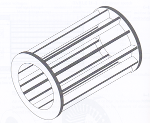
Resembles a squirrel cage, thus this type of motor is often called a squirrel-cage motor. The stator contains a pattern of copper coils arranged in windings. As alternating current is passed through the windings a moving magnetic field is formed near the stator (Induction). This induces a current in the rotor (electromagnetism), creating its own magnetic field. The interaction of these fields produces a torque (turning) on the rotor.
All 3-phase generators (or motors) use a rotating magnetic field. Most power in the world is 3 phase. The concept was originally conceived by Nikola Tesla

who also was aware of radiant energy and or zero point energy. Along with a lot of other stuff (he is as cool as hector).I have included an extensive description and theory of operation of the AC motor with pictures is because if you’re a laymen like me it will help recycle the understanding of the principles of magnetism and current and induction. All should be clearer after reading this so please do.