

This definitive guide is compiled from empirical accounts by those which have successfully completed RV replications.
Layman’s starting from scratch
This is intended to give a crash course from a layman’s perspective for those with out any knowledge of the processes at all. And as quick as possible. There are a few principles and process that are necessary to understand the foundations of what’s going on. This is also aimed at an introduction to Dans RE-OU version 5.1 e-book. You will find also advanced RV ‘R and D’ in this compilation but written in a laymen’s perspective by experimenters which have completed various stages of the RV. For people already poised in electricity please use the index to navigate to the many additions added to this version since first draft.
There is also an alternative tailored course (like this guide) for the beginner just starting electronics (like me) for these ‘type’ of devices. Very clear and introductory.
http://www.geocities.com/captpjk/
Electricity……………………………………………………………………………
Magnets, inductors, electromagnetic inductance and inductance………………… .
AC…………………………………………………………………………………..
Capacitors and capacitance…………………………………………………………
Resonance………………………………………………………………………….
Impedance matching role in resonance related to the RV………………………….
Stochastic resonance……………………………………………………………….
Radiant energy……………………………………………………………………..
Logarithmic gain (1.618) within resonance ……………………………………….
Power factor and power factor correction…………………………………………
Q (reactive power)…………………………………………………………………
RV parts…………………………………………………………………………….
AC induction three phase motor description………………………………………
DCPM RV rotor……………………………………………………………………
walk through and operating principles (theory)……………………………………
Advanced looping principles and resonance collection…………………………....
Rains resonant tank………………………………………………………………
Phils resonant collection…………………………………………………………..
Phil inspired Pulse length frequency circuit……………………………………
Auto phase start resonance collector……………………………………………
Dans collector plug circuit……………………………………………………….
ZPE transformation mechanics theory……………………………………………
Electricity
It is best to think of electricity as a "fluid" which is actually composed of extremely small bits of matter called electrons. (There are other types of electricity or electrical fluidic motion and behaviour but we will focus on this first)
Experimentation has revealed that Objects are composed of extremely small building blocks known as atoms. And that in turn these atoms are composed of smaller components known as particles. The three fundamental particles comprising the atom are photons, neutrons and electrons

In any atom, the protons and neutrons are very tightly bound together because of a much stronger force called the strong nuclear force which has effect only under very short distances However; electrons have significantly more freedom to move around in an atom than either protons or neutrons. In fact, they can be knocked out of their respective positions (even leaving the atom entirely!) by far less energy than what it takes to dislodge particles in the nucleus. If this happens, the atom still retains its chemical identity, but an important imbalance occurs.
Electrons and protons are unique in the fact that they are attracted to one another over a distance. Electrons tend to repel other electrons over a distance, as do protons with other protons. Because of this attraction/repulsion behavior between individual particles, electrons and protons are said to have opposite electric charges. That is, each electron has a negative charge, and each proton a positive charge. In equal numbers within an atom, they counteract each other's presence so that the net charge within the atom is zero (when in equal numbers). The atom of every material has equal numbers of atoms and electrons and neutrons.
However the process of electrons arriving or leaving is exactly what happens when certain combinations of materials are rubbed together: electrons from the atoms of one material are forced by the rubbing to leave their respective atoms and transfer over to the atoms of the other material. It is this attraction over distance which causes the attraction or repulsion between rubbed objects, where electrons are moved away from their original atoms to reside around atoms of another object.
When you rub wax and a glass rod this happens. This is called static electricity.

If electrons leave or extra electrons arrive, the atom's net electric charge will be imbalanced, leaving the atom "charged" as a whole, causing it to interact with charged particles and other charged atoms nearby. The result of an imbalance of this "fluid" (electrons) between objects is called static electricity. It is called "static" because the displaced electrons tend to remain stationary after being moved from one material to another. They remain stationary as they need a conductive material in order to travel. Like a copper wire. (This has many free electrons orbiting around its centre)
The water needs a pipe to flow through
Copper because of the distance of the electrons around the nucleus, allows for freedom of electron flow (conductive) or one could even consider that copper repels electrons, whilst iron attracts it.
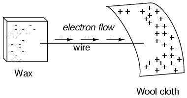
When they flow its electricity (uniform motion of electrons) when you build up a charge between the protons and electrons (as between the materials) its called voltage. Being the potential to move the current (electrons through a conductive material)
The movement or current is called amps or under usually a symbol of I Voltage is the V some times as E (for energy). Voltage is only relative or possible across two points. With out the wool the wax would not have a common electric point for the voltage ready to be transported through the wire. Its Simple voltage is the push and current is the flow.
Note also that when ever electrons flow through a conductor (in this case the copper wire) a magnetic field is produced Which is orientated perpendicular to the direction of flow. If you held your left hand over the wire with thumb out it would look like this.

The spaced lines in the centre bottom represent a battery which is acting like a charge and pump of electrons. The green lines are the magnetic field. The magnetic field encircles this straight piece of current carrying wire. Whilst the magnetic field surrounding a current carrying wire is indeed interesting, it is quite weak for common amounts of current but will increase with the amount of current. To create a stronger magnetic field force with the same amount of electric current we can wrap the wire into a coil shape where the circling magnetic fields around the wire will join to create a larger magnetic field.
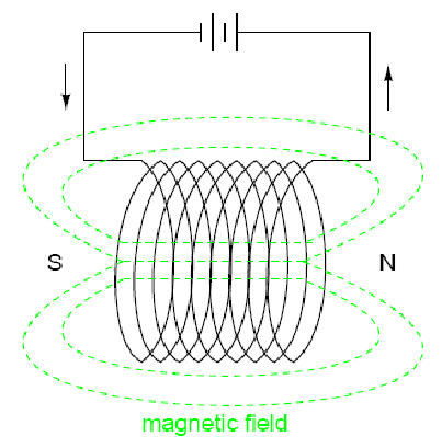
Now we will call the wire is an inductor. An inductor is a passive electrical device that stores energy in a magnetic field.
An inductor is symbolised by an L. in honour of some guy (we don’t have time to go into it :D)Now When ever a wire carries a current there will be a magnetic field.
Inductance reference
also when ever a length of wire is exposed perpendicular magnetic field of changing intensity a voltage is generated!.

This is electromagnetic induction.
Now we recall that the magnetic field produced from a current carrying wire was always perpendicular to that wire, and that the intensity of the magnetic field will vary with the amount of current through it.
Current through wire->magnetic field above wire
Current changes in wire->magnetic field changes
A magnetic field change near wire->voltage is produced.
we can now see that a wire is capable if inducing a voltage along its own length simply due to a change in current through it..
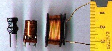
This is called self induction. A changing magnetic field produced by changes in current in the wire inducing voltage along the length of that same wire. If the magnetic fields flux (extent of the field) is enhanced by bending the wire into the shape of a coil AND OR wrapping that coil around a material of high permeability (means easier passage of magnetic field) this effect of self induced voltage will be more intense. An inductor is constructed to take advantage of this effect.
Now if two coils of wire are bought into close proximity with another so the magnetic field of one links to another a voltage will be generated in the second coil as a result. This is called mutual inductance when voltage impressed onto one coil induces a voltage in another. When used as such, this device is known as a transformer:
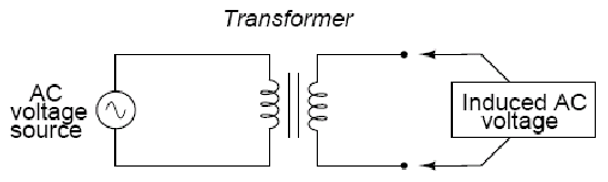
This is an important process and relation in the Roto conversion. Understand these basics.
Note that is the amount of turns in the second wire is smaller the voltage will be stepped down.

If the winding ratio is reversed so that the primary coil has less turns than the secondary coil, the transformer "steps up" the voltage from the source level to a higher level at the load:

The term Resistance is the measure of opposition to electric current. an example is in a lamp which has very small wire at the end, which create friction in the electron flow (like a small pipe with allot of water pressure) the electrons encounter more opposition to motion than they typically would in a thick piece of wire in result this friction releases heat energy (or because electrons have mass and weight if you shoot them through at light speed they disintegrate in heat upon impact) and the light glows white hot. In this example the light would be referred to as a load (resistor). Resistance is essentially friction against the motion of electrons.
Resistance is mathematically symbolized by the letter "R" and is measured in the unit of ohms (never mind ohms). The resistor (the light bulb) on a circuit is the zig zag line (which is its symbol). There is also a voltage drop (lesser push of the current) between points 2 and 3 as it goes through the load (in this case bulb)

Above is a simple design of a single circuit, called a schematic. The lines from the battery are tracing the path of electrons. The battery is acting like a charge/pump of electrons.
For reference in the description where it is stated ‘This series-connection further helps to reduce input current.' the defining characteristic of a series connection is that there is only one path for electrons to flow.
Note: below that there will be voltage drops between points 1 and 4 because of the resistors (light bulbs) the current runs into opposition. Therefore a voltage drop will be a reduction in the current flow.


Also for reference in the description where it is stated that hector (inventor) is connecting the winding in parallel. The defining characteristic of a parallel circuit is that all components are connected across each others leads and that there is never more than two sets of electrically common points. There are many paths for electrons to flow but only one voltage across all components. (No voltage drop)

The voltage is equal across all points. This is because there are only two sets of electrically common points across.

Inductors do not behave the same as resistors. Whereas resistors simply oppose the flow of electrons through them (by dropping a voltage directly proportional to the current), inductors oppose changes in current through them, by dropping a voltage directly proportional to the rate of change of current. Remember that if the current slows down the magnetic field changes around the wire changes-> magnetic field changes around a wire-> a voltage is induced thus the rate of current is effected.
In accordance with Lenz's Law, this induced voltage is always of such a polarity (direction) as to try to maintain current at its present value. That is, if current is increasing in magnitude, the induced voltage will "push against" the electron flow; if current is decreasing, the polarity will reverse and "push with" the electron flow to oppose the decrease. This opposition to current change is called reactance, rather than resistance.
What this means in a practical sense is that the reactance of an inductor dissipates a net energy of zero, quite unlike the resistance of a resistor, which dissipates energy in the form of heat. Mind you, this is for perfect inductors only, which have no wire resistance.
An inductor's opposition to change in current translates to an opposition to alternating current in general (explained next) which is by definition always changing in instantaneous magnitude and direction. This opposition to alternating current is similar to resistance, but different in that it always results in a phase shift between current and voltage, (explained next) and it dissipates zero power. Because of the differences, it has a diferent name: reactance. Reactance to AC is expressed in ohms, just like resistance is, except that it’s mathematical symbol is X instead of R. To be specific, reactance associated with an Inductor is usually symbolized by the capital letter X with a letter L as a subscript, like this: XL
Inductive reactance is the opposition that an inductor offers to alternating current due to its Phase-shifted storage (of voltage to current explained next) and release of energy in its magnetic field.
In the schematic this combined opposition will be a vector (vector meaning a variable quantity that can be resolved into components) combination of resistance and reactance.

In order to express this opposition succinctly, (With concise and precise brevity; to the point) we need a more comprehensive term for opposition to current than either resistance or reactance alone. This term is called impedance.
Impedance: In a circuit it is the total measure of opposition to electric current, from a resistor (resistance like a light bulb resisting making the heat) and inductor (reactance, being a wound coil). RLC Impedance is a very important factor in the operation of the roto conversion attaining it’s over unity (more energy out than in) and will be detailed more with examples after the introduction to phase shift of voltage and current and alternating current.
Alternating current.
In the DC (direct current as from a battery) diagram the symbol on the left is representative of a battery where the electrons charge or pump from the negative terminals towards the positive. I is the symbol for current.

If a machine is constructed to rotate a magnetic field around a set of stationary wire coils with the turning of a shaft, AC voltage will be produced across the wire coils as that shaft is rotated, in accordance with Faraday's Law of electromagnetic induction. This is the basic operating principle of an AC generator, also known as an alternator:

Notice how the polarity (direction) of the voltage across the wire coils reverses as the opposite poles of the rotating magnet pass by. Connected to a load, this reversing voltage polarity will create a reversing current direction in the circuit. The faster the alternator's shaft is turned (determines frequency as well denoting a wave forms shape of ac voltage explained further in the next section), the faster the magnet will spin, resulting in an alternating voltage and current that switches directions more often in a given amount of time. Like the pitch in a musical note higher or lower.
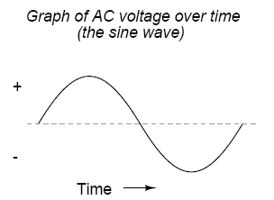
When an alternator produces AC voltage, the voltage switches polarity (direction) over time, but does so in a very particular manner. When graphed over time, the "wave" traced by this voltage of alternating polarity from an alternator takes on a distinct shape, known as a sine wave: This is a picture of what is called a sine wave off a reading from an oscilloscope
The power of alternating current (AC) fluctuates. For domestic use for e.g. light bulbs this is not a major problem, since the wire in the light bulb will stay warm (creating the light through the heat as it glows white hot) for the brief interval while the power drops. Neon lights (and your computer screen) will blink, in fact, but faster than the human eye is able to perceive. For the operation of motors etc. it is useful, however, to have a current with constant power. Also note the magic number 3. thus why 3 phases of voltage are used in a three phase motor.