

Laymen’s rv step by step
Presented at the end of the photo instructions You will find a laymen’s theory of operation (basic). plus further goals and advice from more experienced RV builders for those just starting out like me.
There is another book in this series, for those who know nothing of electricity paralleled at the RV principles (and being consistently worked on like Dans compilation) this is meant to be read first before commencing this part of the series. The is under the title of RV laymen’s theory.
For the advanced R and D engineer, Dans RE –OU version 5.1 is a further advancement into the unknown. When raivo updates his e-book (consolidated knowledge) there will be another as well.
Contents
Modifying your set up…………………………………………………………….
running directly from the grid…………………………………………………….
tuning the alternator for radiant energy…………………………………………
goals and advice…………………………………………………………………..
planning ahead by the numbers…………………………………………………
basic essential steps……………………………………………………………...
measuring the current relation in the RV……………………………………….
Trouble shooting with the alternator exciting…………………………………..
Tuning guide lines for a pulse length frequency adjustable inverter………...
Connecting your load to your alt options ………………………………………
laymen’s theory of operation……………………………………………………..
Equipment used to illustrate the basic RV set up
2 Baldors 7.5 3PH (more detail below)
Inverter xantrex 1200watt modified sine wave
Solar panel 120 watt
Deep cycle 12 volt battery
Basic run and start caps (non electrolytic for run!)
Modifying your set up
You will find from the examples of replications from hectors RV that they are modified in the alternator side. Although this is primarily only cosmetic enabling the two junction boxes to face the front when coupled, this is also done particularly so it makes the system easer to work on when your testing different configurations. Also you will need to follow part of this routine described to remove the fan, because as Dans test prove conclusively the fan takes 32.84
watts!(builds up wind resistance) And is not needed when the motors are operated idling for observation of the processes and learning from the behaviour modified to RV mode, as your not driving the motor in its normal functional peaks. (therefore over heating will not occur)

Hector writes:
Quote: The motor housing screws are removed housing faceplates & rotor are inverted then the 2 junction boxes face to the front and shafts face each other this to be done carefully assuming the stator windings are centered to permit reversal.-end quote
This guide is modeled on the latest recommendations from the groups discussions. Which are two Motors 230/460 VAC 7.5HP 3450- or 1725 RPM 3PH motor 184 TCH frame (with removable external fan
Specifications :baldors motor EM3770T
Catalogue Number: EM3770T
Specification Number: 07H002X790
Horsepower: 7 1/2
Voltage: 230/460
Hertz: 60
Phase: 3
Full Load Amps: 19/9.5
Usable at 208 Volts: N/A
RPM: 1770
Frame Size: 213T
Service Factor: 1.15
Rating: 40C AMB-CONT
Locked Rotor Code: J
NEMA Design Code: A
Insulation Class: F
Full Load Efficiency: 91.7
Power Factor: 81
Enclosure: TEFC
Baldor Type: 0735M
DE Bearing: 6307
ODE Bearing: 6206
Electrical Specification Number: 07WGX790
Mechanical Specification Number: 07H002
Base: RG
Mounting: F1
Source:
http://www.baldor.com/products/detail.asp?1=1&catalog=EM3770T&product=AC+Motors&\family=Premium+Efficiency%7Cvw%5FACMotors%5FPremiumEfficiency
you need DOUBLE COIL motors - this means, that the motor should have 9 or 12 wire terminals. And two identical motors. That's why Hector has stated that it should be 230/460V model - when the dual coils are connected in series, then it is 460V (good for RV prime mover), when in parallel, then it is a 230V motor with twice the amps capacity (excellent for RV alternator operation).
Such double coil motors might be a bit hard to find in Europe or in
Australia. It is advisable to stick to the modeled guide and to order those US 230/460 motors.
The above is the motor that Hector recommended (it's a 1770RPM motor which is a bit more peaceful to operate - less vibration, especially when the coupling between motors is not very good)
current recommendations from EVGRAY on RV motors to use: NA: - DUAL winding motors 230/460VAC 60Hz; 3 to 7.5HP - prime mover 3600rpm, wired for highest voltage (460V 'Y') and apply single-phase 110V
- alternator 3600rpm or lower, wired for lowest voltage (230V) EU: - WYE/Delta motors 230/400VAC 50Hz; 5 to 10 HP - prime mover 3000rpm, wired for highest voltage ('Y') and apply single-phase 100-120VAC (through variac or transformer) - alternator 3000rpm or lower, wired for lowest voltage (in DELTA) In any case the lowest HP is 5HP for 50Hz, as you need to have the same efficiency. (with 60Hz, you can go down to 3HP).So a 4KW motor will do fine.
Before commencing with modifying your set up, you must RE- grease the bearings and put oil on the shaft[s]!!.
This is essential to boast the efficiency by getting rid of drag from factory grease, even in new motors! So far the best stuff I have found is a product called BI-tron, this is a superior lubricating product and protection. I suggest you evaluate this from their site to see what I talking about. One can see from the test comparison that there is no other product on the market which can stand the pressure and protect like BI-tron.
Here is the instructions I got from the representative.
Quote:
If want to improve the lubrication you can use the penetrating spray lubricant on the bearing (with the grease still there) and it will greatly improve the lube.
The bi-tron will work into the bearing. Or if you were to remove the grease you would need to apply new grease and in that you could mix EP Metal Treatment at a 6% ratio to the grease before reapplying the grease. Either way you would still need the grease as the carrier.
The directions and tech data site is www.bi-tron.org and the main website is www.bi-tronaustralia.com. –end quote
Bi-tron is mail order only and not found in the shops, but is the best stuff. Alternatively you can try what Doug conzen uses which is
Quote:
I sprayed my Barings out with carburetor cleaner, took off the plates, then when I add small amount of "krol" lubricant (guy in nuts and bolts store said it is great) it loses a bit of spin is all - now maybe 15 revolutions before coming to stop. Plus I think dura-lube brand is the best lubricant to use. –end quote
Hector Recommendations
Options for solutions Washing in Transmission fluid, reviving & regressing with low friction lube. end
The bearings that look like little wheels, have balls. Do not fondle with these balls because they are accurately machined. But too see the balls you must pop off some seals. These are normally black flat washer things clipped into the sides of our bearing.
Some bearings have metal seals. What we do in this case is break them
out with a screwdriver. But if we have rubber seals we carefully flip them out with a blade ON THE OUT SIDE EDGE. We do not flip them out on the inside edge towards the centre because there is a perfect neat running edge.
We can do all this without taking the bearing off the motor shaft. We pop
them off and slide away from the bearing then wash all the old grease out.
We put new grease in and carefully clip the seals back in place. Now we only
need a little grease, because too much will expand and pop our seals off
without us ever knowing, when the motor is running.

Flipping the rotor step by step.
First choose the alternator side of your 2 motors(any one of the two). Then take the four long bolts that hold the endplates out. Remove the fan too, as it builds up wind resistance , and it is safe to operate the motor with in certain parameters (testing and idling for short periods) with out having to worry for the necessity of the fan.
Part 1

Get a large flat blade screwdriver and look for the indent in the fan side endplate. Use the screwdriver and pry or use a small hammer and tap the screwdriver and get the fan side endplate to separate from the motor frame.
Part 2

You might have to go around the end plate and tap in different places to get it to come off. Once it comes loose you should be able to remove it. i.e. it should come off the shaft. The bearing will still be on the rotor shaft. Now do the same procedure to the output shaft endplate.
This end plate will stay with the rotor. (pictured in part 2) Next slide the rotor out of the motor like the picture above. The rotor is heavy. Just take the rotor out slowly & try not to drag it across the stator core DO NOT DRAG THE ROTOR ACROSS THE STATOR.

Part 3

Part 4
Now take the rotor and front plate (pictured above) and insert it in the other side of the motor where the fan endplate was (opposite side). You will have to use a hammer (or rubber mallet) to tap the endplate back into the motor housing. Make sure to align the bolt holes to the same position they were before disassembly. Next put the fan endplate back on (use mallet and align the bolt holes). Last screw in the long bolts. Check that the rotor spins freely. Wallaaa Your done (pictured below)

Part 5
Note motor is switched around in the opposite direction for alignment to proper acceptation as an alternator coupled to the prime mover with both junction boxes able to face together.

Part 6
Note the original end plate where the fan was is removed and switched to the opposite side whilst the rotor was take out, and the casing of the motor turned around, (inverted) then the rotor with the end plate still attached was placed back inside the motor and all was refasten.
Rv junction box
All credit is given to the mystical one peter (nick is mystic) for this eloquent (meaning Expressing yourself readily, clearly, effectively) organized setting, (as he is a bit of an original hehe )
Make up for a neater presentation and clearer definition of values that the motor is designed for, A Junction box with the values marked out for assigning both the prime mover and the alternators values . The prime mover is wired to 460 V and the alternator is wired to 260. remove the junction box and drill holes for assigning the numbered poles of the motors (wires).
Next assign the values in this casing 460 V for the prime mover by the instructions on the junction box , and connect the values too available outlets.
Here is a model directly off the baldors web site.

the numbers are correct from the list then this is not the standard color code---- according to this list one would wire 4 to 7 yellow to pink 5 to 8 black to red 6 to 9 purple to gray 1 (blue)to (Hi in) & then connect caps junction to here
2 (white) connect to other caps junction (white) 3 (orange)to (Nutral in)


Finished unit should look easily recognizable and readable.

The configurations are in easily recognizable and visible in the order allocated by the voltage assignment from the motors generic schematic (white picture on top of the junction box describing the low/high voltage lead wiring.)
Do this for both the prime mover and the chosen alternator. This will save you having to open the junction boxes all the time and re configure the wiring.
Frame measurements
If you stick to the recommended motors in the guide then your measurements will coincide with the aforementioned but I recommend you measure them your self just to be sure. Otherwise it is not much involved in attaining the perfect alignment measurement base for the motors. You only basically need to measure out the width of the holes in the baldors motors being in my case of 10 mil holes and adequate spacing for the shaft coupling from the end of your desired beam size.
Even though we measured 10 mil holes we found that 10 mil screws didn’t go in very well, therefore we used 8 mill nuts and bolts with washers for better fit.
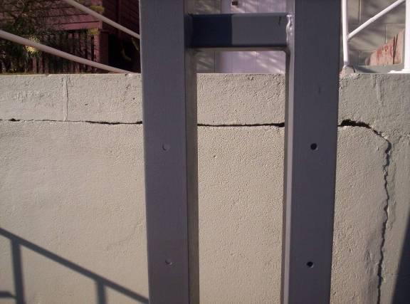
10 mil holes with from the ends. And leave some spacing after the end motor fitting on the out side of the frame.

Finished product.
switching box for start of prime mover

Here pictured we have leads for the battery inverter, caps and a shunt which you will need for tuning. The switch box has two switches assigned for the start capacitor and the run capacitor of the prime mover. [thanks peter mystic!!!]
coupling
you will need to get the key that’s taped inside the shaft, and file and or grind it down to the specifications of your coupling fits. In our case we grinded it down to 7 mil form its original width.

.
That’s peter, I was taking the photos like a Japanese tourist, and not paying attention to what he was doing.
Next fit and align the motors on the frame and connect coupling. If you have the same motors as this guide Your shaft is 1 3/8 inches. I recommend aluminum shafts as opposed to what Dan and I used as they are heavy iron. Rubber coupling is lighter and easier to work with and doesn’t corrode. But iron shaft coupling will allow magnets to be on it, as well as a belt drive. I mention this as some may want to experiment with more capturing.

Those wrinkles were caused by my nagging and obvious questions
Next get your shunt and battery and inverter wired up.
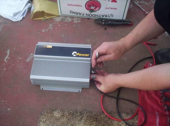

The shunt can be on either positive or negative of the battery lead.