

Maxwell v15 |
|
6.3 |
|
|
Eddy Current – Application Note |
||
Instantaneous Forces on Busbars in Maxwell 2D and 3D
This example analyzes the forces acting on a busbar model in Maxwell 2D and 3D. Specifically, it provides a method for determining the instantaneous force on objects having sinusoidal AC excitation in the Eddy Current Solver. Force vectors in AC problems are a combination of a time-averaged “DC” component and an alternating “AC” component. The alternating component fluctuates at a frequency twice the excitation frequency. Both of these components can be calculated using the formulas below so that the instantaneous force can be determined. Three different force methods are used in this example: Virtual, Lorentz, and the Maxwell Stress Tensor.
|
2 |
∫ |
|
|
|
|
|
|
|
|
|
|
|
F |
= 1 |
|
Re |
J |
|
×B |
dV |
||||||
DC |
|
|
|
|
|
|
|
|
|
|
|
|
|
|
2 |
∫ |
|
|
|
|
|
|
|
|
|
|
|
F |
= 1 |
|
J |
×B |
dV |
evaluated at phase (ωt = degrees) |
|||||||
AC |
|
|
|
|
|
|
|
|
|
|
|
|
|
FINST = FDC + FAC |
|
||||||||||||
Description
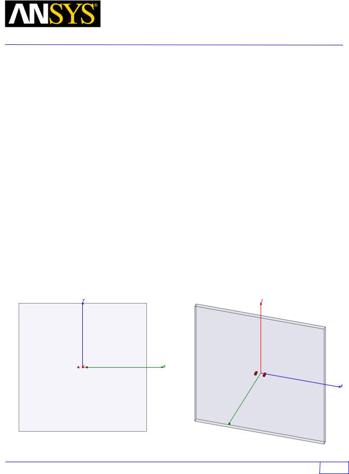
This example will be solved in two parts using the 2D Eddy Current and 3D Eddy Current solvers. The model consists of two 4mm parallel copper busbars separated by a center-center spacing of 16mm. The excitation frequency is 100kHz.
|
|
3D Model |
2D Model |
|
|
|
|
|
|
|
|
ANSYS Maxwell Field Simulator v15 User’s Guide |
6.3 - 1 |

Maxwell v15 |
|
6.3 |
|
|
Eddy Current – Application Note |
||
PART 1 - The 2D Eddy Project
A 2D model of the busbars will be simulated first. Access the Maxwell Project Manager and create a new 2D project called 2dbars. Open the project and change to the Eddy Current solver with an XY drawing plane.
Setup the Design
1.Click on the menu item Project > Insert Maxwell 2D Design
2.Click on the menu item Maxwell 2D > Solution Type ...
o Set Geometry Mode: Cartesian, XY
oSelect the radio button Magnetic: Eddy Current
•Draw the Solution Region
oClick on Draw > Rectangle (Enter the following points using the tab key).
X: -150, Y: -150, Z: 0
dX: 300, dY: 300, dZ: 0
oChange its properties:
Name: Region
Display Wireframe: Checked
o Select View > Fitall > Active View to resize the drawing window.
Create the Model
Now the model can be created. This model also consists of a left and right busbar that have a 4mm square cross-section, however a length of 1 meter is assumed so that the results must be scaled to compare to 3D.
Create the Left Busbar
• Click on Draw > Rectangle
oX: -12, Y: -2, Z: 0
odX: 4, dY: 4, dZ: 0
•Change its properties:
oName: left
o Material: Copper
o Color: Red
ANSYS Maxwell Field Simulator v15 User’s Guide |
6.3 - 2 |
Maxwell v15 |
|
6.3 |
|
|
Eddy Current – Application Note |
||
Create the Right Busbar
•Click on Draw > Rectangle o X: 8, Y: -2, Z: 0
o dX: 4, dY: 4, dZ: 0
•Change its properties:
o Name: right
o Material: Copper o Color: Red
Assign the Boundaries and Sources
The current is assumed to be 1A at 0 degrees in the left busbar and -1A at 60 degrees in the right busbar. A no-fringing vector potential boundary will be assigned to the outside of the 2D problem region which is also the default boundary for all 3D projects. This forces all flux to stay in the solution region.
1. The boundary must be set on the solution region.
o Choose Edit > Select > Edges to change the selection mode from object to edge. o While holding down the CTRL key, choose the four outer edges of the region.
oClick on Maxwell 2D > Boundaries> Assign > Vector Potential
Value: 0
Phase: 0
OK
oWhen done, choose Edit > Select > Object to object selection mode.
1.Select left from the history tree
oClick on Maxwell 2D > Excitations > Assign > Current
Name: Current1
Value: 1A
Phase: 0
Type: Solid
Reference Direction: Positive
2.Select right from the history tree.
oClick on Maxwell 2D > Excitations > Assign > Current
Name: Current2
Value: 1A
Phase: 60
Type: Solid
Reference Direction: Negative
ANSYS Maxwell Field Simulator v15 User’s Guide |
6.3 - 3 |

Maxwell v15 |
|
6.3 |
|
|
Eddy Current – Application Note |
||
Turn on the Eddy Effects in the winding
In order to consider the skin effects in the busbars, you must manually turn on the eddy effect.
1.Choose Maxwell 2D > Excitations > Set Eddy Effects ...
2.Verify that the eddy effect is checked for both the left and right conductors.
Assign the Parameters
In order to automatically calculate force on an object, it must be selected in the Parameters panel. In 2D, only the virtual force can be automatically calculated. Later, the Lorentz force will be calculated manually in the Post Processor after solving the project.
1.Select the left busbar by clicking on it.
2.Click on Maxwell 2D > Parameters > Assign > Force
3.Click OK to enable the force calculation.
Add an Analysis Setup
1.Click Right on the Analysis folder in the Model Tree and select Add Solution Setup…
2.On the General tab, re-set the Number of passes to 15.
3.Percent Error to 0.01
4.On the Solver tab, re-set the Adaptive Frequency to 100kHz.
Solve the Problem
1.Save the project by clicking on menu item File > Save As
2.Select the menu item Maxwell 2D > Validation Check to verify problem setup
3.Click on Maxwell 2D > Analyze All.
ANSYS Maxwell Field Simulator v15 User’s Guide |
6.3 - 4 |