
- •Maxwell 3D User’s Guide
- •Maxwell 3D User’s Guide
- •Maxwell 3D Keyboard Shortcuts
- •User Defined Primitives
- •Maxwell and the Finite Element Method
- •The Finite Element Method in 1-D
- •The Finite Element Method in 1-D
- •The Finite Element Method in 1-D
- •The Finite Element Method in 1-D
- •3D Example: Puck Magnet above a steel plate
- •Adaptive Mesh Refinement
- •Adaptive Mesh Refinement
- •Adaptive Mesh Refinement
- •Adaptive Mesh Refinement
- •Adaptive Mesh Refinement
- •Adaptive Mesh Refinement
- •Plot of |B| on surface of the Plate (DC after 16 passes)
- •Adaptive Mesh Refinement
- •Plot of |B| on surface of the Plate (DC after 22 passes)
- •Convergence
- •Convergence definition through use of additional variables
- •The “Solve” Procedure in Maxwell
- •Summery
- •Example: Team Problem #20
- •Instantaneous Forces on Busbars in Maxwell 2D and 3D
- •Description
- •Setup the Design
- •Draw the Solution Region
- •Change its properties:
- •Create the Model
- •Create the Left Busbar
- •Create the Right Busbar
- •Assign the Boundaries and Sources
- •Assign the Parameters
- •Add an Analysis Setup
- •Solve the Problem
- •View the Results
- •Create a Plot of Force vs. Time
- •Setup the Design
- •Draw the Solution Region
- •Change its properties:
- •Create the Model
- •Create the Left Busbar
- •Assign the Boundaries and Sources
- •Assign the Parameters
- •Add an Analysis Setup
- •Solve the Problem
- •View the Results
- •Create a Plot of Force vs. Time
- •MSC Paper #118 "Post Processing of Vector Quantities, Lorentz Forces, and Moments

Maxwell 3D
electronic design automation software
user’s guide – Maxwell 3D |
ANSYS Inc • Southpointe • 275 Technology Drive • Canonsburg, PA 15317

The information contained in this document is subject to change without notice. ANSYS Inc. makes no warranty of any kind with regard to this material, including, but not limited to, the implied warranties of merchantability and fitness for a particular purpose. ANSYS Inc. shall not be liable for errors contained herein or for incidental or consequential damages in connection with the furnishing, performance, or use of this material.
© 2010 ANSYS Inc. All rights reserved.
ANSYS Inc.
Southpointe
275 Technology Drive
Canonsburg, PA 15317 ansysinfo@ansys.com http://www.ansys.com
(T) 724-746-3304 (F) 724-514-9494
Ansoft Maxwell, Simplorer, RMxprt and Optimetrics and any and all ANSYS, Inc. brand, product, service and feature names, logos and slogans are registered trademarks or trademarks of ANSYS, Inc. or its subsidiaries in the United States or other countries. All other brand, product, service and feature names or trademarks are the property of their respective owners.
New editions of this manual will incorporate all material updated since the previous edition. The manual printing date, which indicates the manual’s current edition, changes when a new edition is printed. Minor corrections and updates which are incorporated at reprint do not cause the date to change. Update packages may be issued between editions and contain additional and/or replacement pages to be merged into the manual by the user. Note that pages which are rearranged due to changes on a previous page are not considered to be revised.
Edition: REV6.0
Date: 13 March 2012
Software Version: 15

Maxwell 3D User’s Guide
Contents
This document discusses some basic concepts and terminology used throughout the ANSYS Maxwell application. It provides an overview of the following topics:
1. Overview
2.Solution Types
2.0- General Finite Element Information
2.1- Magnetostatic Analysis
2.2- Eddy Current Analysis
2.3- Transient Magnetic Analysis
2.4- Electrostatic Analysis
2.5- DC Conduction Analysis
2.6- Electric Transient Analysis
3.Mesh Overview
3.0- Meshing Process and Operations
3.1- Geometry Import & Healing
3.2- Mesh Operation Examples
3.3- Adaptive Meshing
4. Data Reporting
4.0- Data Plotting
4.1- Field Calculator
5.Examples – Magnetostatic
5.1– Magnetic Force
5.2– Inductance Calculation
5.3– Stranded Conductors
5.4– Equivalent Circuit Extraction (ECE) Linear Movement
5.5– Anisotropic Materials
5.6– Symmetry Boundaries
5.7– Permanent Magnet Magnetization
5.8– Master/Slave boundaries
6.Examples – Eddy Current
6.1– Asymmetrical Conductor with a Hole
6.2– Radiation Boundary
6.3- Instantaneous Forces on Busbars

Maxwell 3D User’s Guide
7.Examples – Transient
7.1– Switched Reluctance Motor (Stranded Conductors)
7.2– Rotational Motion
7.3– Translational Motion
7.4– Core Loss
8.Examples – Electric
8.1– Mass Spectrometer
9.Examples – Basic Exercises
9.1– Electrostatic
9.2– DC Conduction
9.3– Magnetostatic
9.4– Parametrics
9.5– Magnetic Transient
9.6– Magnetic Transient with Circuit Editor
9.7– Post Processing
9.8– Optimetrics
9.9– Meshing
9.10– Scripting
9.11– Linear ECE
9.12– Eddy Current with ANSYS Mechanical
9.13– Rotational Transient Motion
9.14– Basic Electric Transient
9.15– Permanent Magnet Assignment
9.16– Electric Transient High Voltage Line
10.Examples – Optimetrics
10.1– Gapped Inductor
11.Examples – Motors
11.1– Motor Application Note – Prius Motor
12.Examples – Multiphysics Coupling
12. 1 – Maxwell Magnetostatic to Mechanical Coupling (IGBT)
12.2- Maxwell Eddy Current to FLUENT Coupling
12.3– Maxwell Transient to FLUENT Coupling
12.4– Maxwell Electrostatic to Mechanical Coupling (Capacitor)
Maxwell v15 Overview
Presentation
1
v15
Maxwell 3D is a high-performance interactive software package that uses finite element analysis (FEA) to solve electric, magnetostatic, eddy current, and transient problems.
ANSYS Maxwell Field Simulator v15 – Training Seminar |
P1-1 |
|
|

Maxwell v15 Overview
Presentation
1
v15
Maxwell solves the electromagnetic field problems by solving Maxwell's equations in a finite region of space with appropriate boundary conditions and
— when necessary — with user-specified initial conditions in order to obtain a solution with guaranteed uniqueness.
Electric fields:
Electrostatic fields in dielectrics
Electric fields in conductors
A combination of the first two with conduction solutions being used as boundary conditions for an electrostatic problem.
Magnetostatic fields Eddy current fields Transient fields
ANSYS Maxwell Field Simulator v15 – Training Seminar |
P1-2 |
|
|
Maxwell v15 Overview
Presentation
1
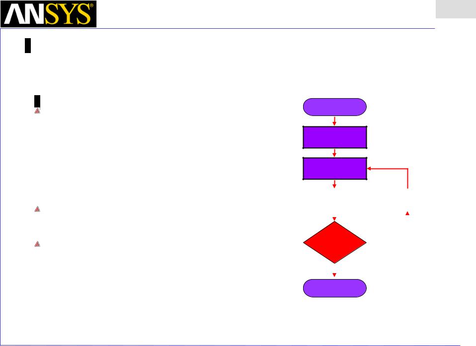
FEM and adaptive meshing
In order to obtain the set of algebraic equations to be solved, the geometry of the problem is discretized automatically into small elements (e.g., tetrahedra in 3D).
All the model solids are meshed automatically by the mesher.
The assembly of all tetrahedra is referred to as the finite element mesh of the model or simply the mesh.
Start
Field Solution
Generate
Initial Mesh
Compute
Fields
Perform |
|
|
Refine |
||||
Error Analysis |
|
|
Mesh |
||||
|
|
|
|
|
|
|
|
|
|
|
|
|
|
|
|
|
|
|
|
|
|
|
|
Has |
|
|
No |
|
|
||
|
|
|
|
|
|||
Stopping |
|
|
|
|
|
||
|
|
|
|
|
|||
Criteria been |
|
|
|
|
|
||
met? |
|
|
|
|
|
||
|
|
|
|
|
|
|
|
|
|
Yes |
|
|
|
|
|
|
|
|
|
|
|
|
|
Stop |
|
|
|
|
|
||
Field Solution |
|
|
|
|
|
||
ANSYS Maxwell Field Simulator v15 – Training Seminar |
P1-3 |
|
|

Maxwell v15 Overview
Presentation
1
GUI - Desktop
The complex functionality built into the Maxwell solvers is accessed through the main user interface (called the desktop).
Problem can be setup in a fairly arbitrary order (rather than following the steps in a precise order as was required in previous versions of Maxwell).
A “validation check” insures that all required steps are completed.
ANSYS Maxwell Field Simulator v15 – Training Seminar |
P1-4 |
|
|
Maxwell v15 Overview
Presentation
1
ACIS solid modeling kernel
The underlying solid modeling technology used by Maxwell products is provided by ACIS geometric modeler. ACIS version 21 is used in Maxwell v15.
Users can create directly models using primitives and operations on primitives.
In addition, users can import models saved in a variety of formats (sm2
.gds .sm3 .sat .step .iges .dxf .dwg .sld .geo .stl .prt .asm)
When users import models into Maxwell products, translators are invoked that convert the models to an ACIS native format (sat format).
Maxwell can also import CAD files (CATIA, Pro-E and Unigraphics) files directly. The import can be parametric or non-parametric
Exports directly .sat, .dxf, .sm3, .sm2, .step, .iges
|
|
|
ANSYS |
Maxwell Field Simulator v15 – Training Seminar |
P1-5 |
|
|
|

Maxwell v15 Overview
Presentation
1
Curved vs. Faceted Surfaces
The Maxwell 3D interface encourages the use of curved surfaces Many CAD programs use curved surfaces
Curved surfaces do not directly translate into a better solution, due to the nature of the finite tetrahedral mesh elements – there is always some deviation from the curved surface and the meshed surface
Using faceted surfaces can be more robust in many cases
Faceted surfaces may converge in fewer iterations and may use fewer mesh elements – therefore, there is a possible large speed improvement!
Curved |
Faceted |
|
|
|
|
|
|
|
|
|
ANSYS Maxwell Field Simulator v15 – Training Seminar |
P1-6 |
||
|
|
|
|
Maxwell v15 Overview
Presentation
1
v15 Supported platforms
 Windows XP 32-bit Service Pack 2
 Windows Server 2003 32-bit Service Pack 1
 Windows XP 64-bit Service Pack 2
 Windows Server 2003 64-bit Service Pack 1
 Windows HPC Server 2008
 Windows 7 Business Editions (32-bit and 64-bit versions)
 Red Hat (32 and 64 bit) v.4, v.5
  SuSE (32 and 64 bit) v10, v11
ANSYS Maxwell Field Simulator v15 – Training Seminar |
P1-7 |
|
|

 Maxwell v15 Overview
System requirements (Windows)
32-Bit System Requirements
Minimum System Requirements:
Processor: All fully compatible 686 (or later) instruction set processors, 500 MHz Hard Drive Space (for Maxwell software): 200 MB, RAM: 512 MB
Recommended Minimum Configuration (for Optimal Performance):
Processor: All fully compatible 786 (or later) instruction set processors, 1 GHz Video card: 128-bit SVGA or PCI Express video card
Hard Drive Space (for Maxwell software and temporary files): 500 MB, RAM: 2 GB
64-bit System Requirements
Minimum System Requirements:
Supported processors: AMD Athlon 64, AMD Opteron, Intel Xeon with Intel EM64T support, Intel Pentium 4 with Intel EM64T support
Hard Drive Space (for Maxwell software): 200 MB, RAM: 2 GB
Recommended Minimum Configuration (for Optimal Performance):
Supported processors: AMD Athlon 64, AMD Opteron, Intel Xeon with Intel EM64T support, Intel Pentium 4 with Intel EM64T support
Video card: 128-bit SVGA or PCI Express video card
Hard Drive Space (for Maxwell software and temporary files): 700 MB, RAM: 8 GB
Presentation
1
ANSYS Maxwell Field Simulator v15 – Training Seminar |
P1-8 |
|
|
Maxwell v15 |
Overview |
Presentation |
|
|
|
|
|
1 |
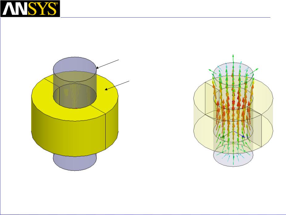
• Quick Example – Coil |
• Maxwell 3D |
|
|
• 3D field solver |
|
|
• Solves for the fields in an arbitrary volume |
|
Core (Steel_1008)
Coil (120 Conductors, Copper)
ANSYS Maxwell Field Simulator v15 – Training Seminar |
P1-9 |
|
|
Maxwell v15 Overview
Presentation
1
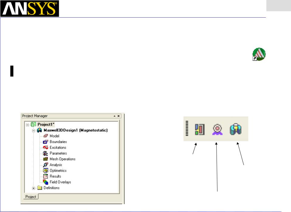
• Starting Maxwell
•Click the Microsoft Start button, select Programs, and select the Ansoft > Maxwell 15 > Windows 64-bit > Maxwell 15
• Or Double click on the Maxwell 15 icon on the Windows Desktop
•Adding a Design
•When you first start Maxwell a new project will be automatically added to the Project Tree.
•To insert a Maxwell Design to the project, select the menu item Project > Insert Maxwell Design
Toolbar:
Insert Maxwell 2D Design
Insert Maxwell 3D Design
Insert RMxprt Design
ANSYS Maxwell Field Simulator v15 – Training Seminar |
P1-10 |
|
|
|
Maxwell v15 |
|
Presentation |
|
Overview |
1 |
|
|
|
||
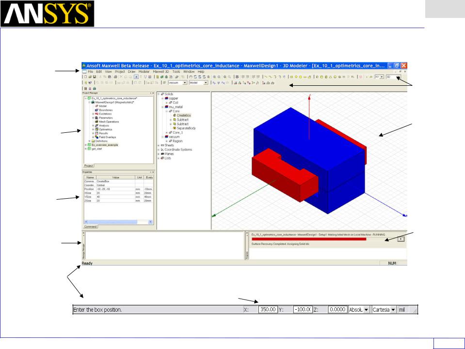
• |
Maxwell Desktop |
|
|
|
Menu |
|
|
|
bar |
Toolbars |
|
|
|
||
|
Project |
3D Modeler |
|
|
Manager |
Window |
|
|
with project |
|
|
|
tree |
|
|
|
Property |
|
|
|
Window |
|
|
|
|
Progress |
|
|
Message |
Window |
|
|
Manager |
|
|
|
Status |
|
|
|
bar |
|
|
|
Coordinate Entry Fields |
|
|
ANSYS Maxwell Field Simulator v15 – Training Seminar |
|
P1-11 |
|
Maxwell v15 Overview
Presentation
1
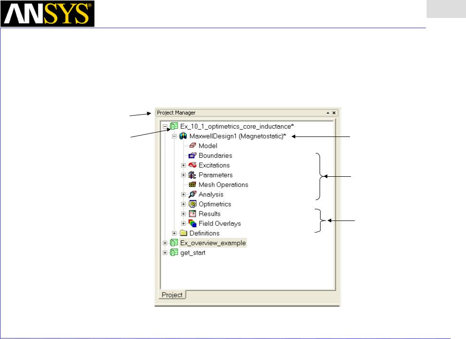
•Maxwell Desktop – Project Manager
•Multiple Designs per Project
•Multiple Projects per Desktop
•Integrated Optimetrics Setup (requires license for analysis)
Project Manager Window
Project
Design Automation 
•Parametric
•Optimization
•Sensitivity
•Statistical
Design
Design Setup
Design Results
|
|
|
|
|
|
|
|
ANSYS Maxwell Field Simulator v15 – Training Seminar |
P1-12 |
||
|
|
|
|
Maxwell v15 Overview
Presentation
1
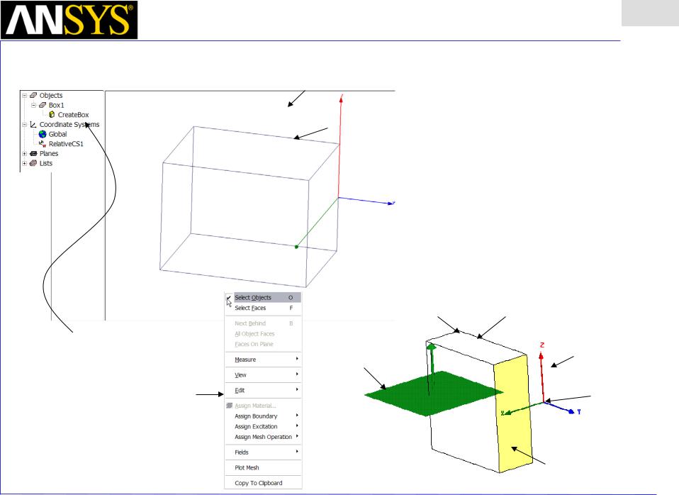
•Maxwell Desktop – 3D Modeler
3D Modeler design tree (history)
|
3D Modeler Window |
Graphics |
Model |
area |
|
Vertex |
Edge |
|
Coordinate System (CS)
|
Plane |
Context menu |
Origin |
(right mouse |
|
click on 3D |
|
modeler |
|
window) |
|
|
Face |
|
Model |
ANSYS Maxwell Field Simulator v15 – Training Seminar |
P1-13 |
|
|

Maxwell v15 Overview
Presentation
1
•Set Solution Type
•To set the solution type:
1.Select the menu item Maxwell 3D> Solution Type
2.Solution Type Window:
1.Choose Magnetostatic
2.Click the OK button
•To edit notes: Maxwell > Edit Notes
•Maxwell - Solution Types
•Magnetostatic - Static magnetic fields, forces, torques, and inductances caused by DC currents, static external magnetic fields, and permanent magnets. Linear or nonlinear materials.
•Eddy Current - Sinusoidally-varying magnetic fields, forces, torques, and impedances caused by AC currents and oscillating external magnetic fields. Linear materials only. Full wave solver considers displacement currents. Induced fields such as skin and proximity effects considered.
•Transient Magnetic - Transient magnetic fields caused by time-varying or moving electrical sources and permanent magnets. Linear or nonlinear materials. Induced fields such as skin and proximity effects considered. Sources can be DC, sinusoidal, or transient voltages or currents. Can use external schematic circuit or link to Simplorer.
•Electrostatic - Static electric fields, forces, torques, and capacitances caused by voltage distributions and charges. Linear materials only.
•DC Conduction - Voltage, electric field, and the current density calculated from the potential. The resistance matrix can be derived quantity. Insulators surrounding the conductors can also be added to the simulation to calculate the electric field everywhere including the insulators
•Transient Electric - Transient electric fields caused by time-varying voltages, charge distributions, or current excitations in inhomogeneous materials. The transient electric field simulator computes time-varying electric fields. Electric potential is the solution quantity.
|
|
ANSYS Maxwell Field Simulator v15 – Training Seminar |
P1-14 |
|
|

 Maxwell v15
•Set Model Units
•To set the units:
1.Select the menu item Modeler > Units
2.Set Model Units:
1.Select Units: mm
2.Click the OK button
•Set Default Material
•To set the default material:
1.Using the Modeler Materials toolbar, choose Select
2.Select Definition Window:
1.Type steel_1008 in the Search by Name field
2.Click the OK button
Presentation
Overview 1
|
|
|
|
|
|
|
|
|
|
|
|
|
|
|
|
|
|
|
|
|
|
|
|
|
|
|
|
|
|
|
|
|
|
|
|
ANSYS Maxwell Field Simulator v15 – Training Seminar |
P1-15 |
||||
|
|
|
|
|
|
Maxwell v15 Overview
Presentation
1
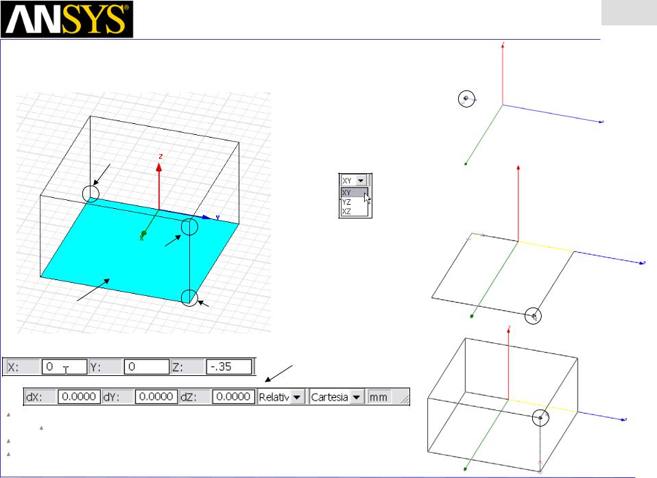
•Modeler – Create a Primitive
Point 1
Point 3
Point 1
 Grid Plane
Note: Point 1 and Point 2 are drawn in the grid plane, while Point 3 is drawn in the 3rd direction
Base Rectangle |
Point 2 |
|
Point 2
 Coordinate Entry Fields
Point 3
The Coordinate Entry fields allow equations to be entered for position values.
Examples: 2*5, 2+6+8, 2*cos(10*(pi/180)).
Variables are not allowed in the Coordinate Entry Field
Note: Trig functions are in radians. Need to specify extension deg if specified in degrees.
Ex. Sin(90deg)
ANSYS Maxwell Field Simulator v15 – Training Seminar |
P1-16 |
|
|

 Maxwell v15
•Modeler – Object Properties
Commands
(dimensions and history)
Attributes
(properties of the object)
Presentation
Overview 1
In History Tree:
Attributes
Commands
ANSYS Maxwell Field Simulator v15 – Training Seminar |
P1-17 |
|
|
 Maxwell v15
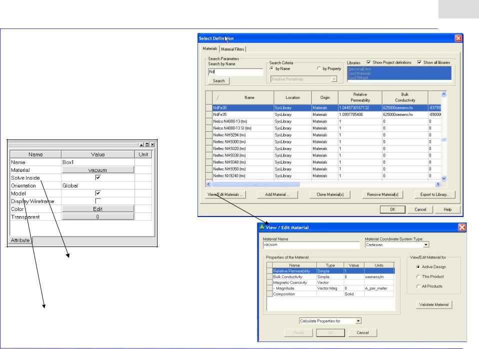
•Modeler – Attributes
Solve Inside – if unchecked meshes but no solution inside (like the old exclude feature in material manager)
Model – if unchecked, the object is totally ignored outside of modeler with no mesh and no solution
Presentation
Overview 1
ANSYS Maxwell Field Simulator v15 – Training Seminar |
P1-18 |
|
|
 Maxwell v15
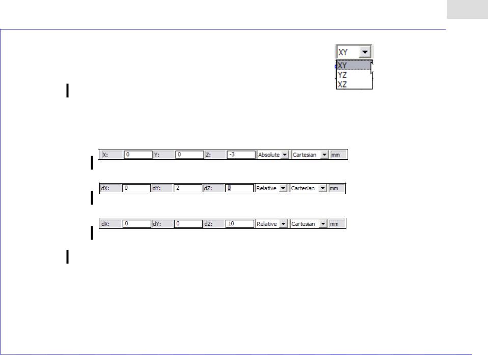
•Set Grid Plane
•To set the Grid Plane:
•Select the menu item Modeler > Grid Plane > XY
•Create Core
Presentation
Overview 1
•To create the coax pin:
1.Select the menu item Draw > Cylinder
2.Using the coordinate entry fields, enter the center position
•X: 0.0, Y: 0.0, Z: -3.0, Press the Enter key
4.Using the coordinate entry fields, enter the radius of the cylinder
•dX: 0.0, dY: 2.0, dZ: 0.0, Press the Enter key
5.Using the coordinate entry fields, enter the height of the cylinder
•dX: 0.0, dY: 0.0 dZ: 10.0, Press the Enter key
•Continued on Next Page
ANSYS Maxwell Field Simulator v15 – Training Seminar |
P1-19 |
|
|

Maxwell v15 Overview
Presentation
1
•Create Core (Continued)
•To Parameterize the Height
1.Select the Command tab from the Properties window
2.Height: H
3.Press the Tab key
4.Add Variable Window
1.Value: 10
2.Unit: mm
3.Click the OK button
•To set the name:
1.Select the Attribute tab from the Properties window.
2.For the Value of Name type: Core
•To set the material:
1.Select the Attribute tab from the Properties window
2.Click on the button in Material value: set to steel_1008
•To set the color:
1.Select the Attribute tab from the Properties window.
2.Click the Edit button
•To set the transparency:
1.Select the Attribute tab from the Properties window.
2.Click the OK button
•To finish editing the object properties
1.Click the OK button
•To fit the view:
1.Select the menu item View > Visibility > Fit All > Active View
|
|
ANSYS Maxwell Field Simulator v15 – Training Seminar |
P1-20 |
|
|
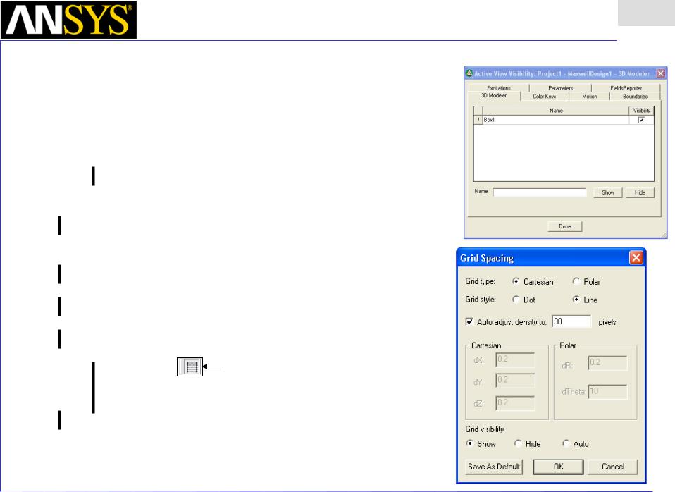
Maxwell v15 Overview
Presentation
1
•Modeler - Views
•View > Modify Attributes >
•Orientation – Predefined/Custom View Angles
•Lighting – Control angle, intensity, and color of light
•Projection – Control camera and perspective
•Background Color – Control color of 3D Modeler background
•View > Visibility > Active View Visibility - Controls the display of: 3D Modeler Objects, Color Keys, Boundaries, Excitations, Field Plots
•View > Options – Stereo Mode, Drag Optimization, Color Key Defaults, Default Rotation
•View > Render > Wire Frame or Smooth Shaded (Default)
•View > Coordinate System > Hide or Small (Large)
•View > Grid Setting – Controls the grid display
Toolbar: Toggle Grid Visibility
ANSYS Maxwell Field Simulator v15 – Training Seminar |
P1-21 |
|
|

Maxwell v15 Overview
Presentation
1
•Changing the View
•Toolbar
|
|
Rotate Around |
|
|
|
Zoom In/Out |
Fit Selected |
|
|
|
|
Current Axis |
|
|
|
Predefined View Angles |
|||
|
|
|
|
|
|
||||
|
|
|
|
|
|
|
|
|
|
Pan |
|
|
|
|
|
|
|
|
|
|
|
|
|
|
|
|
|
Top |
|
|
|
|
|
|
|
||||
|
|
|
|
|
|
|
|
|
|
|
|
|
|
Rotate |
|
Around |
Dynamic Zoom |
Fit All |
|
|
|
|
|
|
|
||||
|
|
|
|
|
|
|
|||
|
|
Rotate Around |
|
|
|||||
|
|
Screen Center |
|
|
|||||
|
|
Model Center |
|
|
|
|
|
|
|
• Context Menu |
Left |
Right |
Bottom
•Shortcuts
•Since changing the view is a frequently used operation, some useful shortcut keys exist. Press the appropriate keys and drag the mouse with the left button pressed:
•ALT + Drag – Rotate
•In addition, there are 9 pre-defined view angles that can be selected by holding the ALT key and double clicking on the locations shown on the next page.
•
•
Shift + Drag - Pan
ALT + Shift + Drag – Dynamic Zoom
|
|
ANSYS Maxwell Field Simulator v15 – Training Seminar |
P1-22 |
|
|
