

2 lec Eng
.pdfMathematical Models of Systems

Differential equations of linear systems
u(t)
Input signal
System
y(t)
Output signal
n – the order of a system
 – constant coefficients
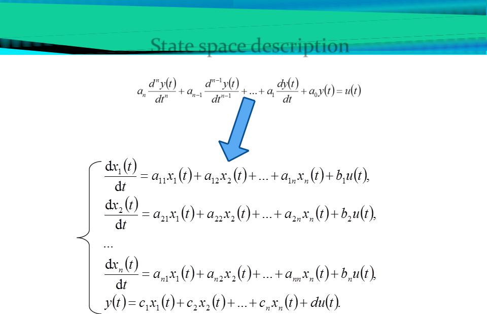
State space description
variable substitution

State space description
In case of multi-inputs and multi-outputs (MIMO systems) we have:
|
Inputs |
|
Outputs |
|
|||
u1(t) |
|
|
|
|
|
|
y1(t) |
|
|
|
|
|
|
||
|
|
|
|
|
|
||
u2(t) |
|
|
System |
|
|
|
y2(t) |
... |
|
... |
|
||||
|
|
|
|
||||
um(t) 

 yr(t)
yr(t)
m – number of inputs, r – number of outputs

State space description
In matrix representation we have:
– State equation |
– State vector |
– Output equation
–Vector of input signals
–Vector of output signals

Block diagram description
Typical elements of block diagrams
link
node (junction)
gain (amplification factor)
u |
y |
an arrow indicates the direction of signal transmission
one signal is transmitted to the different elements
y t Ku t ,
where K – a constant coefficient

Block diagram description
Typical elements of block diagrams
comparison (sum) element
u y
z
u y
z
product element
u y z
y t u t z t
y t u t z t
y t u t z t
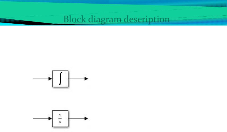
Block diagram description
Typical elements of block diagrams
integrator
u(t) |
y(t) |
dy |
u t |
||
|
|
dt |
|||
|
or |
|
|
|
|
u(s) |
y(s) |
y s |
1 |
u s |
|
|
|
s |
|||

Graphical representation of State space
D
U |
|
|
|
Y |
X |
1 |
X |
||
|
|
|
C |
|
|
|
s |
|
|
|
|
|
|
|
|
|
A |
|
|
A - System matrix |
|
|
C - The observation matrix |
|
B - Input transmission |
|
|
D - Input to Output transmission |
|
matrix |
|
|
matrix |
|

The relationship between the Transfer function and the Block diagram description