

Металлоконструкции 3 курс 1 семестр Шафрай / промышленные здания мк на англ
.pdf
Best Practice in Steel Construction - INDUSTRIAL Buildings
Contents
The Steel Construction Institute (SCI) develops and promotes the effective use of steel in construction. It is an independent,
membership based organisation. SCI’s research and development activities cover multi-storey structures, industrial buildings, bridges, civil engineering and offshore engineering. Activities encompass design guidance on structural steel, light steel and stainless steels, dynamic performance, fire engineering, sustainable construction, architectural design, building physics (acoustic and thermal performance), value engineering, and information technology.
www.steel-sci.org
This publication presents best practice for the design of steel construction technologies used in industrial buildings, and is aimed at architects and other members of the design team in the early stages of planning an industrial building project. It was prepared as one of a series of three under an RFCS dissemination project Euro-Build in Steel (Project n° RFS2-CT-2007-00029).
The project’s objective is to present design information on best practice in steel, and to take a forward look at the next generation of steel buildings. The other publications cover best design practice in commercial and residential buildings.
The Euro-Build project partners are: ArcelorMittal
Bouwen met Staal
Centre Technique Industriel de la Construction Métallique (CTICM) Forschungsvereinigung Stahlanwendung (FOSTA)
Labein Tecnalia SBI
The Steel Construction Institute (SCI) Technische Universität Dortmund
Although care has been taken to ensure, to the best of our knowledge, that all data and information contained herein are accurate to the extent that they relate to either matters of fact or accepted practice or matters of opinion at the time of publication, the partners in the Euro-Build project and the reviewers assume no responsibility for any errors in or misinterpretations of such data and/or information or any loss or damage arising from or related to their use.
ISBN 978-1-85942-063-8
© 2008. The Steel Construction Institute.
This project was carried out with financial support from the European Commission’s
Research Fund for Coal and Steel.
Front cover: Mors company building, Opmeer / Netherlands
Photograph by J. and F. Versnel, Amsterdam
01 Introduction
1
02 Key Design Factors
2
03 Support Structures
15
04 Roof & Wall Systems
25
05 National Practice
33
06 Case Studies
47
EURO-BUILD in Steel
Introduction 01
01 Introduction
Large enclosures or industrial type buildings are very common in business parks, leisure and sports buildings. Their functionality and architectural quality are influenced by many factors, e.g. the development plan, the variety of usages and the desired quality of the building. Steel offers numerous possibilities to achieve both pleasant and flexible functional use.
For buildings of large enclosure, the economy of the structure plays an important role. For longer spans, the design is optimised in order to minimise the use of materials, costs and installation effort. Increasingly, buildings are designed to reduce energy costs and to achieve a high degree of sustainability.
Industrial buildings use steel framed structures and metallic cladding of all types. Large open spaces can be created that are efficient, easy to maintain, and are adaptable as demand changes. Steel is chosen on economic grounds, as well as for other aspects such as fire, architectural quality and sustainability.
In most cases, an industrial building is not a single structure, but is extended by office and administration units or elements such as canopies. These additional elements can be designed in a way that they fit into the whole building design.
This publication describes the common forms of industrial buildings and large enclosures, and their range of application in Europe. Regional differences that may exist depending on practice, regulations and capabilities of the supply chain,
are presented in Section 5.
The same technologies may be extended to a range of building types, including sports and leisure facilities, halls, supermarkets and other enclosures.
Figure 1.1 Leisure building using a steel framed structure
EURO-BUILD in Steel

02 Best Practice in Steel Construction - INDUSTriAL Buildings
02 Key Design Factors
The design of industrial buildings is affected by many factors. The following general guidance is presented to identify the key design factors and the benefits offered by steel construction.
Industrial buildings are generally designed as enclosures that provide functional space for internal activities, which may involve use of overhead cranes or suspended equipment as well as provision of office space or mezzanine floors.
Various structural forms have been developed over the last 30 years that optimise the cost of the steel structure in relation to the space provided. However, in recent years, forms of expressive structure have been used in architectural applications of industrial buildings, notably suspended and tubular structures.
A single large hall is the main feature of most industrial buildings.
The construction and appearance of an industrial building provides the design engineer with a wide range of possible configurations in order to
realise the architectural ideas and the functional requirements. Generally, an industrial building has a rectangular floor space, which is extendable in its
long direction. The design of the building has to be coordinated with functional requirements and the energy-saving concept, including lighting.
The following forms of industrial buildings represent an overview of the possible architectural and constructional solutions. Exhibition halls, railway stations, airports and sports arenas tend to be special structures. However, the following general issues are restricted to
‘standard’ floor plans.
Forms of Industrial Buildings
The most elementary system used for an industrial building consists of two columns and a beam. This configuration can be modified in numerous ways using various types of connections between the beams and columns and for the column base. The types of structures most commonly used in industrial buildings are portal frames with hinged column bases.
Portal frames provide sufficient in-plane stability, and thus only require bracings for out-of-plane stability.
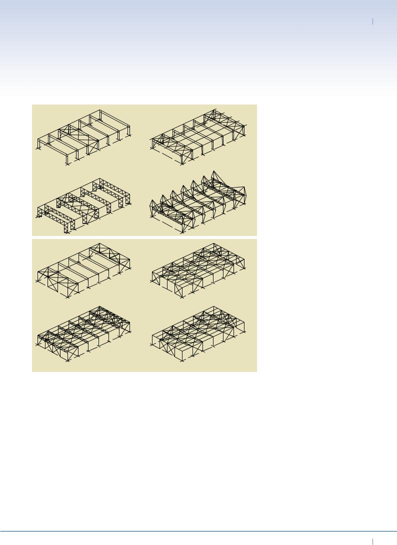
Figure 2.1 shows a variety of rigid frames with fixed (a) or hinged (b) column bases.
Fixed column bases may be considered when heavy cranes are used, as they deflect less under horizontal forces.
Hinged column bases have smaller foundations and simple base connections. In examples (c) and (d), the structure is located partly outside the building, and so details concerning the piercing of the building envelope have to be designed carefully. The complex detail in these types of structure also serve architectural purposes.
In Figure 2.2, different structures consisting of beam and columns are presented. Figure 2.2 (a) shows an example of a structure without purlins, that is stiffened by diaphragm action in the roof and bracings in the walls. In Figure 2.2 (b), purlins are used, leading to a simple design of the roof cladding, which has reduced spans and only serves to support vertical loads. The roof is stiffened by plan bracing. The structure without purlins may offer a more pleasant
Forms of Industrial
Buildings
Fire Safety
Building Physics
Loading
Concept Design
Considerations
Floors
Service Integration
Lighting
EURO-BUILD in Steel
Key Design Factors 02
(a ) Frame with fixed column bases
(c) Frame with lattice girders
(a ) Structure without purlins, roof stiffened by trapezoidal sheeting
(c) Lattice girder with purlins
appearance when viewed from the inside. Figures 2.2 (c) and (d) show lattice trusses and cable suspended beams, which may be beneficial to achieve larger spans, as well as desirable for visual reasons.
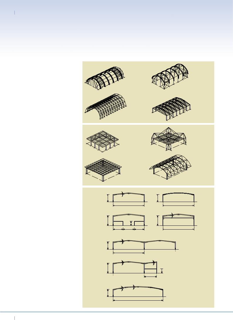
Arch structures offer advantageous loadcarrying behaviour as well as having a pleasant visual appearance. In Figure 2.3 (a), a building with a three-hinged arch is shown. Alternatively, the structure can be elevated on columns or integrated in a truss structure, as in Figure 2.3 (d).
The forms of buildings with primary and secondary structural elements described above are all directional structures, for which the loads are carried primarily on
(b)Frame with hinged column bases
(d) Suspended portal frame |
Figure 2.1 Examples of rigid |
|
framed sructures |
||
|
(b) Structure with purlins
(d) Cable suspended beams with purlins
individual directional load paths.
Spatial structures and space trusses are non-directional structures; they can be expanded, but would become heavy for long spans. Figure 2.4 shows some examples of spatial structures.
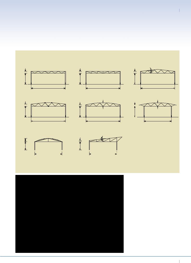
Portal frames
Steel portal frames are widely used in most of the European countries because they combine structural efficiency with functional application.
Various configurations of portal frames can be designed using the same structural concept as shown in Figure 2.5. Multi-bay frames can also be designed, as in Figure 2.5 (e) and (f), either using single or pairs of internal columns.
Figure 2.2 Examples of column and beam structures
In addition to the primary steel structure, a wide range of secondary components has also been developed, such as
cold formed steel purlins, which also provide for the stability of the framework (see Figures 2.6 and 2.7).
These simple types of structural systems can also be designed to be architecturally more appealing by using curved members, cellular or perforated beams etc., as illustrated in Figure 2.8.
Innovative structural systems have also been developed in which portal frames are created by moment resisting connections using articulations and ties, as given in Figure 2.9.
EURO-BUILD in Steel
02 Best Practice in Steel Construction - INDUSTriAL Buildings
Figure 2.3 Examples of curved or arch structures
Figure 2.4 Examples of spatial structures
Figure 2.5 Various forms of portal frames
(a ) Three-hinge lattice |
(b) Elevated curved beams |
arch with purlins |
|
(c) Arch-structure using space frame |
(d) Elevated curved trusses |
(a ) Girder grid on columns |
(b) Suspended girder grid |
with fixed bases |
|
(c) Space frame on columns |
(d) Curved space frame on |
||
with fixed bases |
|
columns with fixed bases |
|
6˚ |
|
|
|
6 m |
|
|
6 m |
|
25 - 40 m |
|
25 - 30 m |
(a) Portal frame - medium span |
(b) Curved portal frame |
||
|
|
|
6˚ |
8 m |
|
|
8 m |
|
3.5 m |
|
|
8 m |
9 m |
8 m |
25 m |
(c) Portal frame with mezzanine floor |
(d) Portal frame with overhead crane |
||
6˚ |
|
|
|
6 m
25m
(e)Two bay portal frame
6˚ |
6˚ |
8 m
 3.5 m
3.5 m
10m
(f)Portal frame with integral office
10˚ 3˚
6 m
40m
(g)Mansard portal frame
EURO-BUILD in Steel

Key Design Factors 02
Figure 2.6 Linked single bay portal frame
Figure 2.7 Two bay portal frame with purlins and roof bracing
Kingspan Ltd
Figure 2.8 Curved beams used in a portal frame structure
EURO-BUILD in Steel

02 Best Practice in Steel Construction - INDUSTriAL Buildings
Figure 2.9 Innovative momentresisting connections in an industrial building
Figure 2.10 Installation process for a modern portal frame
Barrett Steel Buildings Ltd
The installation process of the primary structure and secondary members, such as purlins, is generally carried out using mobile cranes, as illustrated in Figure 2.10.
Lattice trusses
Long span industrial buildings can be designed with lattice trusses, using C, H or O sections. Lattice trusses tend to be beam and column structures and are rarely used in portal frames. Various configurations of lattice trusses are illustrated in Figure 2.11. The two generic forms are W or N bracing arrangements. In this case, stability is generally provided by bracing rather than rigid frame action.
However, columns can also be constructed in a similar way, as illustrated in Figure 2.13, in order to provide in plane stability.
Using lattice structures, a comparatively high stiffness and load bearing resistance can be achieved while minimising material use. Besides the ability to create long spans, lattice structures are attractive and enable simple service integration.
A pinned structure is an idealisation used in design. Moment-resisting connections can be designed using bolted or welded connections. The resulting additional
internal forces are accounted for in the design of the lattice members, when the lattice truss acts to stabilise the building against lateral loads.
Suspended structures
By using suspended structures, longspan buildings with high visual and architectural quality can be realised.
The division into members that are predominantly subject to either tension or compression permits the design of lightweight structures. However, structures that save on materials use do not necessarily lead to economic solutions.
EURO-BUILD in Steel
Key Design Factors 02
1.5 m |
1.5 m |
|
1.5 m |
6˚ |
|
|
|||
8 m |
8 m |
|
8 m |
|
25 m |
|
25 m |
|
25 m |
(a) Lattice girder - W form |
|
(b) Lattice girder - N form |
|
(c) Duo-pitch lattice girder |
1.5 m |
1.0 m |
2.5 m |
1.0 m |
2.5 m |
|
|
|||
8 m |
8 m |
|
8 m |
|
25 m |
|
25 m |
|
20 m |
(d) Articulated lattice girder |
|
(e) Curved lattice girder |
|
(f) Curved lattice truss and canopy |
|
1.0 m |
6˚ |
|
|
2.5 m |
|
|
|
|
|
|
|
|
|
6 m |
6 m |
|
|
|
|
|
|
|
|
|
|
|
|
|
|
|
|
|
|
|
20 m |
|
|
|
|
|
20 m |
|
|
|
|
|
|
|
|||||||||
|
|
|
||||||||||
(g) Articulated bow-string |
|
|
(h) Mono-pitch lattice girder with canopy |
|||||||||
Figure 2.11 (Above) Various forms of lattice truss used in industrial buildings
Figure 2.12 (Left) Lattice truss using tubular members
EURO-BUILD in Steel

02 Best Practice in Steel Construction - INDUSTriAL Buildings
Figure 2.13 Lattice frame using
lattice columns |
|
|
|
Particularly in space structures, the joints |
the following fire safety issues should |
performing fire tests, three levels of fire |
|
may be very complex and more time |
be addressed: |
design calculations: |
|
consuming to construct and install. |
• Means of escape (number of |
Level 1: Classification of structural |
|
Therefore, possible applications of this |
|
emergency exits, characteristics of |
components by using tables. |
type of structure are industrial buildings |
|
exit signs, number of staircases, |
Level 2: Simplified calculation methods. |
that also serve architectural purposes |
|
width of doors). |
Level 3: Advanced calculation methods. |
rather than merely functional buildings. |
• Fire spread (including fire resistance |
Building physics |
|
|
|
and reaction to fire). |
|
Suspended structures can be designed |
• Smoke and heat exhaust |
Thermal insulation |
|
by extending columns outside the building |
|
ventilation system. |
The main purpose of thermal insulation |
envelope, as illustrated in Figure 2.14. |
• Active fire fighting measures (hand |
in industrial buildings is to ensure an |
|
Suspended structures accomplish longer |
|
extinguishers, smoke detectors, |
adequate indoor climate depending |
spans, although the suspension cables or |
|
sprinklers, plant fire brigade). |
on the use of the building. During the |
rods also penetrate the building envelope, |
• Access for the fire brigade. |
heating season, one of the main |
|
and can be obstructive to the use of the |
|
|
functions of the building envelope is |
external space. |
Fire resistance requirements should be |
to reduce the heat loss by means of |
|
|
based on the parameters influencing fire |
effective insulation. This is particularly |
|
Lattice and suspended structures are |
growth and development, which include: |
true for buildings with normal indoor |
|
complex and are not covered in detail in |
• Risk of fire (probability of fire |
temperatures, such as retail stores, |
|
this Best Practice Guide. |
|
occurrence, fire spread, fire duration, |
exhibition halls and leisure centres, |
Fire Safety |
|
fire load, severity of fire, etc.). |
it is true to a lesser extent for |
• |
Ventilation conditions |
buildings with low indoor temperatures, |
|
Even though the general context of fire |
• |
(air input, smoke exhaust). |
such as workshops and warehouses. |
safety regulations is the same throughout |
Fire compartment |
|
|
Europe, national differences do exist. |
|
(type, size, geometry). |
For large panels, thermal bridges |
For example a single-storey industrial |
• Type of structural system. |
and airtightness of joints have a major |
|
building in the Netherlands with a |
• |
Evacuation conditions. |
influence on the energy-balance of |
compartment size of 50 x 100 m has no |
• Safety of rescue team. |
the building. The thermal insulation |
|
requirements concerning fire resistance, |
• Risk for neighbouring buildings. |
has to be placed without gaps and |
|
whereas in France, a fire resistance of |
• Active fire fighting measures. |
the building envelope must be sealed |
|
30 minutes is required in many cases, |
The new generation of European |
and made airtight at longitudinal and |
|
and in Italy the requirement is possibly as |
transverse joints. |
||
high as 90 minutes. At the design stage, |
regulations allow, in addition to |
|
|
EURO-BUILD in Steel