

Металлоконструкции 3 курс 1 семестр Шафрай / промышленные здания мк на англ
.pdfKey Design Factors 02
In the summer, the role of the building envelope is to reduce the effects of solar gain on the interior space. The summer heat reduction depends on the total area and orientation of openings, as well as the effectiveness of solar protection measures.
Condensation risk
Thermal and moisture protection are linked closely, because damage arising from high local humidity is often the result of missing or improperly installed thermal insulation. On the other hand, lack of moisture protection can lead to condensation in the construction,
which in turn affects the effectiveness of the thermal insulation.
In multi-skin roof or wall constructions, condensation risk has to be controlled by installing a vapour barrier on the inner skin of the structure. Wall constructions that are vapour proof on both sides,
like sandwich panels, prevent diffusion. However, the humidity in the internal space also has to be regulated by air conditioning. Section 4 covers roof and floor systems.
Acoustic insulation
In all European countries, minimum requirements exist on the sound insulation of buildings. In addition,
for industrial buildings, it may be necessary to limit values of acoustic emissions from particular machinery.
In steel framed buildings, acoustic insulation is mainly achieved by the construction of the building envelope. All measures of acoustic insulation are based on the following physical principles:
•Interruption of transmission, e.g. by using multi-skin constructions.
•Sound absorption, e.g. by using perforated sheeting or cassettes.
•Reducing response by increasing the mass of a component.
For single sound sources, a local enclosure or isolation is recommended. In order to reach a high level of acoustic insulation, special sound-absorbing roof and wall cladding are effective. For multiskin panels the level of sound insulation can be controlled by varying the acoustic operating mass. Due to the complexity of this issue, it is recommended to consult the specialist manufacturers.
Loading
The actions and combinations of actions described in this section should be considered in the design of a singlestorey industrial building using a steel structure. Imposed, snow and wind loads
Figure 2.14 Suspended structure used at the Renault Factory, Swindon, UK built in the 1980’s
Architect:Richard Rogers Partnership
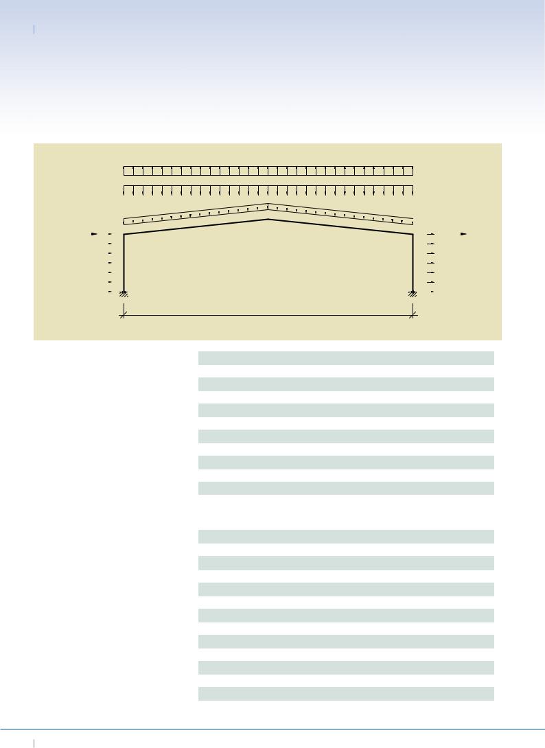
are given in Eurocodes EN 1991 1 1, 1991 1 3 and 1991 1 4. Table 2.1 shows the relevant actions and structural components and Figure 2.15 shows a typical load scheme.
Vertical loads
Self weight
Where possible, unit weights of materials should be checked with manufacturers’ data. The figures given in Table 2.2 may be taken as typical of roofing materials used in the pre-design of a portal frame construction. The self weight of the steel frame is typically 0.2 to 0.4 kN/m2, expressed over the plan area.
Service loads
Loading due to services will vary greatly, depending on the use of the building. In a portal frame structure, heavy point loads may occur from such items as suspended walkways, runway and lifting beams or air handling units. The following loads may be used for pre-design:
•A nominal load over the whole of the roof area of between 0.1 and
0.25 kN/m² on plan depending on the use of the building, and whether or not a sprinkler system is provided.
Imposed load on roofs
EN 1991-1-1 and -3 define characteristic
EURO-BUILD in Steel
02 Best Practice in Steel Construction - INDUSTriAL Buildings
wind uplift
|
snow load |
|
|
|
|||||||||||||||||||||||||||||||||||||||||||||||||||||||||||||||
|
|
|
|
|
|
|
|
|
|
|
|
|
|
|
|
|
|
|
|
|
|
|
|
|
|
|
|
|
|
|
|
|
|
|
|
|
|
|
|
|
|
|
|
|
|
|
|
|
|
|
|
|
|
|
|
|
|
|
|
|
sway |
||||||
|
dead load |
|
|
|
|
|
|
|
|
|
|
|
|
|
|
|
|
|
|
|
|
|
|
|
|
|
|
|
|
|
|
|
|
|
|
|
|
|
|
|
|
|
|
|
|
|
|
|
|
|
|
|
|
|
|
|
|
|
|
|
|
||||||
sway |
|
|
|
|
|
|
|
|
|
|
|
|
|
|
|
|
|
|
|
|
|
|
|
|
|
|
|
|
|
|
|
|
|
|
|
|
|
|
|
|
|
|
|
|
|
|
|
|
|
|
|
|
|
|
|
|
|
|
|
|
|
|
|
|
|
imperfection |
|
|
|
|
|
|
|
|
|
|
|
|
|
|
|
|
|
|
|
|
|
|
|
|
|
|
|
|
|
|
|
|
|
|
|
|
|
|
|
|
|
|
|
|
|
|
|
|
|
|
|
|
|
|
|
|
|
|
|
|
|
|
|
|
|
|
|
|
|
imperfection |
|
|
|
|
|
|
|
|
|
|
|
|
|
|
|
|
|
|
|
|
|
|
|
|
|
|
|
|
|
|
|
|
|
|
|
|
|
|
|
|
|
|
|
|
|
|
|
|
|
|
|
|
|
|
|
|
|
|
|
|
|
|
|
|
|
||
wind |
|
|
|
|
|
|
|
|
|
|
|
|
|
|
|
|
|
|
|
|
|
|
|
|
|
|
|
|
|
|
|
|
|
|
|
|
|
|
|
|
|
|
|
|
|
|
|
|
|
|
|
|
|
|
|
|
|
|
|
|
|
|
wind |
||||
|
|
|
|
|
|
|
|
|
|
|
|
|
|
|
|
|
|
|
|
|
|
|
|
|
|
|
|
|
|
|
|
|
|
|
|
|
|
|
|
|
|
|
|
|
|
|
|
|
|
|
|
|
|
|
|
|
|
|
|
|
|
||||||
|
|
|
|
|
|
|
|
|
|
|
|
|
|
|
|
|
|
|
|
|
|
|
|
|
|
|
|
|
|
|
|
|
|
|
|
|
|
|
|
|
|
|
|
|
|
|
|
|
|
|
|
|
|
|
|
|
|
|
|
|
|
suction |
|||||
pressure |
|
|
|
|
|
|
|
|
|
|
|
|
|
|
|
|
|
|
|
|
|
|
|
|
|
|
|
|
|
|
|
|
|
|
|
|
|
|
|
|
|
|
|
|
|
|
|
|
|
|
|
|
|
|
|
|
|
|
|
|
|
|
|||||
|
|
|
|
|
|
|
|
|
|
|
|
|
|
|
|
|
|
|
|
|
|
|
|
|
|
|
|
|
|
|
|
|
|
|
|
|
|
|
|
|
|
|
|
|
|
|
|
|
|
|
|
|
|
|
|
|
|
|
|
|
|
|
|
|
|
|
|
|
|
|
|
|
|
|
|
|
|
|
|
|
|
|
|
|
|
|
|
|
|
|
|
|
|
|
|
|
|
|
|
|
|
|
|
|
|
|
|
|
|
|
|
|
|
|
|
|
|
|
|
|
|
|
|
|
|
|
|
|
|
|
|
|
|
|
|
|
|
|
|
|
|
|
|
|
|
|
|
|
|
|
|
|
|
|
|
|
|
|
|
|
|
|
|
|
|
|
|
|
|
|
|
|
|
|
|
|
|
|
|
|
|
|
|
|
|
|
|
|
|
|
|
|
|
|
|
|
|
|
|
|
|
|
|
Frame span
Figure 2.15 Loading scheme on a portal frame
Table 2.1 Actions and relevant structural components
Table 2.2 Typical weights of roofing materials
|
Action |
Applied to |
|
|
Self-weight |
Cladding, purlins, frames, foundation |
|
|
Snow |
Cladding, purlins, frames, foundation |
|
|
Concentrated snow |
Cladding, purlins, (frames), foundation |
|
|
Wind |
Cladding, purlins, frames, foundation |
|
|
Wind (increase on single element) |
Cladding, purlins, fixings |
|
|
Wind (peak undertow) |
Cladding, purlins, (fixings) |
|
|
Thermal actions |
Envelope, global structure |
|
|
Service loads |
Depends on specification: roofing, purlins, frames |
|
|
Crane loads |
Crane rails, frame |
|
|
Dynamic loads |
Global structure (Depends on building use and locality) |
|
|
Second order effects |
Wall bracings, columns |
|
|
(Sway imperfections) |
||
|
|
|
|
|
|
|
|
|
Material |
Weight (kN/m²) |
||
|
Steel roof sheeting (single skin) |
0.07 |
- 0.20 |
|
|
Aluminium roof sheeting (single skin) |
0.04 |
|
|
|
Insulation (boards, per 25 mm thickness) |
0.07 |
|
|
|
Insulation (glass fibre, per 100 mm thickness) |
0.01 |
|
|
|
Liner trays (0.4 mm – 0.7 mm thickness) |
0.04 |
- 0.07 |
|
|
Composite panels (40 mm – 100 mm thickness) |
0.10 |
- 0.15 |
|
|
Purlins (distributed over the roof area) |
0.03 |
|
|
|
Steel decking |
0.20 |
|
|
|
Three layers of felt with chippings |
0.29 |
|
|
|
Slates |
0.40 |
/ 0.50 |
|
|
Tiling (clay or plain concrete) |
0.60 |
- 0.80 |
|
|
Tiling (concrete interlocking) |
0.50 |
- 0.80 |
|
|
Timber battens (including timber rafters) |
0.10 |
|
|
|
|
|
|
|
10 EURO-BUILD in Steel

Key Design Factors 02
values of various types of imposed loads on roofs:
•A minimum load of 0.6 kN/m² (on plan) for roof slopes less than 30° is applied, where no access other than for cleaning and maintenance is intended.
•A concentrated load of 0.9 kN - this will only affect the sheeting design.
•A uniformly distributed load due to snow over the complete roof area. The value of the load depends on the building’s location and height above sea level. If multi-bay portal frames with roof slopes are used, the effect of concentrated snow loads in the valleys has to be coonsidered.
•A non-uniform load caused by snow drifting across the roof due to wind blowing across the ridge of the building and depositing more snow on the leeward side. This is only considered for slopes greater than 15° and will not therefore apply to most industrial buildings.
Horizontal loads
Wind loading
Wind actions are given by EN 1991 1 4. Wind loading rarely determines the size of members in low-rise single span portal frames where the height : span ratio is less than 1:4. Therefore, wind loading can usually be ignored for preliminary design of portal frames, unless the height-span ratio is large, or if the dynamic pressure is high. Combined wind and snow loading is often
critical in this case.
However, in two span and other multispan portal frames, combined wind and vertical load may often determine
the sizes of the members, when alternate internal columns are omitted. The magnitude of the wind loading can determine which type of verification
has to be provided. If large horizontal deflections at the eaves occur in combination with high axial forces, then second order effects have to be considered in the verification procedure.
Wind uplift forces on cladding can be relatively high at the corner of the building and at the eaves and ridge. In these areas, it may be necessary to reduce the spacing of the purlins and side rails.
Imperfections
Equivalent horizontal forces have to be considered due to geometrical and structural imperfections. According to EN 1993 1 1 for frames sensitive to buckling in a sway mode, the effect of imperfections should be allowed for in
frame analysis by means of an equivalent imperfection in the form of:
•initial sway deflections; and / or
•individual bow imperfections of members.
Other horizontal loads
Depending on the project, additional horizontal loading may have to be considered, such as earth pressure, force due to operation of cranes, accidental actions and seismic action.
Concept design considerations
General issues
Prior to the detailed design of an industrial building, it is essential to consider many aspects such as:
•Space optimization.
•Speed of construction.
•Access and security.
•Flexibility of use.
•Environmental performance.
•Standardization of components.
•Infrastructure of supply.
•Service integration.
•Landscaping.
•Aesthetics and visual impact.
•Thermal performance and air-tightness.
•Acoustic insulation.
•Weather-tightness.
•Fire safety.
•Design life.
•Sustainability considerations.
•End of life and re-use.
In the first instance, it is necessary to identify the size of the enclosure and to develop a structural scheme, which will provide this functional space taking into account all the above considerations. The importance of each of these considerations depends on the type of building. For example, the requirements concerning a distribution centre will be different from those of a manufacturing unit.
To develop an effective concept design, it is necessary to review these considerations based on their importance, depending on the type of building. Table 2.3 presents a matrix which relates the importance of each consideration to particular types of industrial buildings. Note that this matrix is only indicative, as each project will be different. However, the matrix can serve as a general aid.
Compartmentation & mixed use
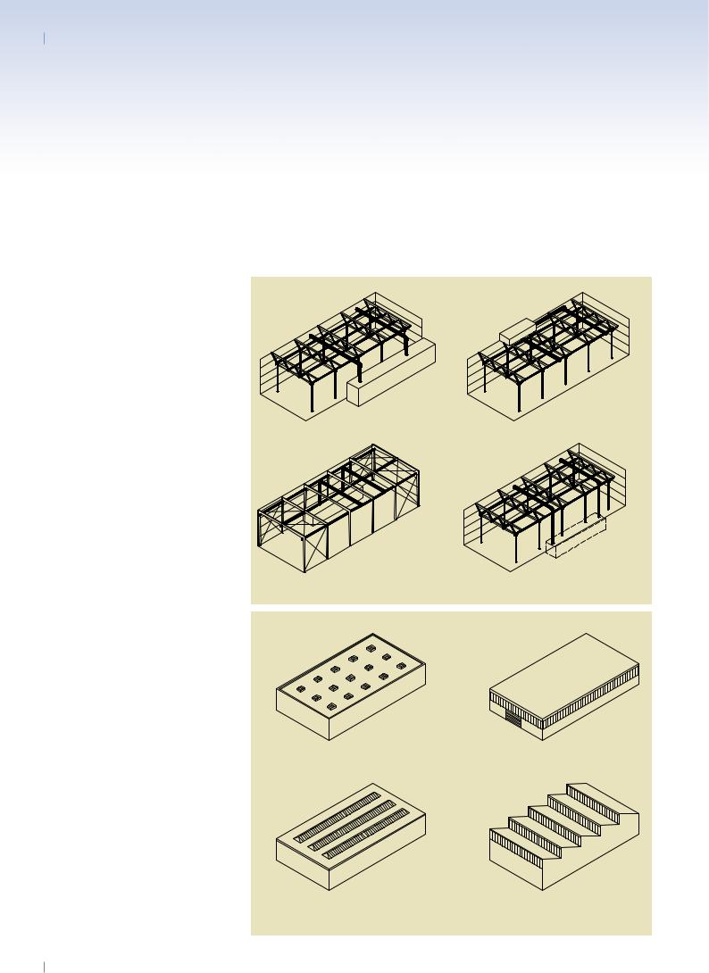
Increasingly, larger industrial buildings are designed for mixed use, i.e. in most cases integrated office space and / or staff rooms for the employees are provided. There are different possible locations for these additional spaces and uses, as shown in Figure 2.16:
•For single-storey industrial buidings, creation of separate space inside the building and possibly two storeys high, separated by
internal walls.
•In an external building, directly connected to the hall itself.
•For two-storey industrial buildings, partly occupying the upper floor.
This leads to special concept design requirements concerning the support structure and the building physics performance. If the office area is situated on the upper storey of the industrial building, it may be designed as a separate structure enclosed by
the structure of the building. In this case, floor systems from commercial buildings can be used, often based on composite
EURO-BUILD in Steel 11

02 Best Practice in Steel Construction - INDUSTriAL Buildings
Considerations for concept design
Type of single-storey industrial buildings
Space optimization |
Speed of construction |
Access and Security |
Flexibility of use and space |
Environmental performance |
Standardization of components |
Specialist infra structure |
Sustainability |
End of life and reuse |
Services integration |
Landscaping |
Aesthetics and visual impact |
Thermal performance and air tightness |
Acoustic isolation |
Weather tightness |
Design life |
High bay warehouses |
|
|
|
|
|
|
|
|
|
|
|
|
|
|
|
|
|
Industrial manufacturing |
|
|
|
|
|
|
|
|
|
|
|
|
|
|
|
|
|
facilities |
|
|
|
|
|||||||||||||
|
|
|
|
|
|
|
|
|
|
|
|
|
|
|
|
|
|
Distribution centres |
|
|
|
|
|
|
|
|
|
|
|
|
|
|
|
|
|
Retail superstores |
|
|
|
|
|
|
|
|
|
|
|
|
|
|
|
|
|
Storage / cold storage |
|
|
|
|
|
|
|
|
|
|
|
|
|
|
|
|
|
Small scale fabrication |
|
|
|
|
|
|
|
|
|
|
|
|
|
|
|
|
|
facilities |
|
|
|
|
|
||||||||||||
|
|
|
|
|
|
|
|
|
|
|
|
|
|
|
|
|
|
Office and light |
|
|
|
|
|
|
|
|
|
|
|
|
|
|
|
|
|
manufacturing |
|
|
|||||||||||||||
|
|
|
|
|
|
|
|
|
|
|
|
|
|
|
|
|
|
Processing plants |
|
|
|
|
|
|
|
|
|
|
|
|
|
|
|
|
|
Leisure centres |
|
|
|
|
|
|
|
|
|
|
|
|
|
|
|
|
|
Sports hall complexes |
|
|
|
|
|
|
|
|
|
|
|
|
|
|
|
|
|
Exhibition halls |
|
|
|
|
|
|
|
|
|
|
|
|
|
|
|
|
|
Aircraft or maintenance |
|
|
|
|
|
|
|
|
|
|
|
|
|
|
|
|
|
hangars |
|
||||||||||||||||
|
|
|
|
|
|
|
|
|
|
|
|
|
|
|
|
|
|
Legend |
No tick = Not important |
|
= important |
|
= very important |
|
|
|
|
|
|
|
|||||
Table 2.3 Important design factors for industrial buildings
structures, e.g. integrated floor beams.
Another possible solution is to attach the office to the main structure. This requires particular attention to be paid to the stabilisation of the combined parts of the building.
Apart from structural issues, special attention has to be paid to:
Fire protection
For large industrial buildings, fire compartmentation may play an important role in
the design, even if there is no internal office space. In order to prevent fire spread, the compartment size is limited to a certain value. Therefore fire walls have to be provided for separation and should ensure at least 60 and often 90 minutes fire resistance. This is even more vital if hazardous goods are stored in the building.
Because the office is designed for use by a larger number of people, fire safety demands are stricter. If the offices are
located on the top floor of the building, additional escape routes are required and active fire fighting measures have to be considered. Fire-spread has to be prevented from one compartment to another, which can be achieved, for example by a composite slab between the office and industrial space.
Thermal insulation
As for fire safety, offices also have higher requirements on thermal insulation.
12 EURO-BUILD in Steel

Key Design Factors 02
office |
|
office |
|
|
|
office hall
|
hall |
|
|
|
hall |
|
|
|
||||
|
|
|
|
|
|
|
|
|
|
|
|
|
|
|
|
|
|
|
|
|
|
|
|
|
|
|
|
|
|
|
|
|
|
|
|
|
|
|
(a) inside |
(b) outside |
(c) on top floor |
In industrial buildings used for storage purposes of non-sensitive goods, thermal insulation may not be required. In offices, however, a high level of comfort is needed, which makes thermal insulation necessary. Therefore the interfaces between the cold and the warm compartments have to be designed to provide adequate insulation.
Acoustic performance
Especially in industrial buildings with noise-intensive production processes,
a strict separation between the production unit and the office areas has to be realised.
This may require special measures for acoustic insulation, depending on the production processes.
Floors
In most cases, the floors for industrial buildings are used for vehicles or heavy machinery. They are designed to support heavy loads and have to be ’flat’. Concentrated loads due to vehicles, machines, racking and containers have to be considered, depending on the application.
Most industrial buildings have a concrete floor with a minimum thickness of
150 mm on top of a layer of sand or gravel, which is also at least 150 mm thick. For large floor areas, a sliding layer between the base layer and the concrete
is required, typically using two layers of synthetic material.
Service integration
For industrial buildings, special requirements for building services are often defined, which may be necessary for the operation of machines and manufacturing lines.
The service integration should be taken into account in the early planning stages. In particular, the position and size of ducts should be coordinated with the structure and provisions for natural lighting.
The use of structural systems, such as cellular beams and trusses, can facilitate integration of services and help to achieve a coherent appearance
of the building.
The design of the servicing machinery and rooms can be of major importance in industrial buildings. Centralisation of the building services can offer the advantage of easy maintenance. Figure 2.17 shows different possible solutions of the positioning of the service rooms.
Natural ventilation reduces the reliance on air conditioning systems, which in turn means a reduction in the building’s CO2 emissions. The effectiveness of natural
Figure 2.16 Possible location of an office attached to an industrial building
ventilation depends on the size and orientation of the building. Roof vents are a common option for natural ventilation in buildings without suitably large openings, however these need to be carefully positioned so as to maximize their performance. Hybrid ventilation systems are now popular in industrial buildings. They use predominantly natural ventilation, but with mechanically driven fans to improve predictability of performance over a wider range of weather conditions.
Mechanical Heat and Ventilation Recovery (MHVR) systems use the heat from the exiting warm stale air to heat up the fresh cool air as it enters the building. The warm air is vented out of the building alongside the incoming fresh air, allowing heat transfer from the exiting to the incoming air. Although this heat transfer will never be 100% efficient, the use of MHVR systems can significantly reduce the amount of energy required to warm the fresh air to a comfortable level.
Further issues which may need consideration in services design include:
•The possible affect of elements for solar protection on air exchange.
•Odour extraction.
•Control of humidity.
•Control of airtightness.
•Acoustic insulation.
EURO-BUILD in Steel 13
02 Best Practice in Steel Construction - INDUSTriAL Buildings
Lighting
Requirements for the lighting of industrial buildings depend on the type of use.
The concept and arrangement of openings to provide natural lighting permit diversity in architectural design.
Rooflights and gable glazed roofs are common, along with lightbands in the façade (Figure 2.18). Openings for natural lighting can serve as smoke and heat outlets in case of fire.
Well-designed natural daylighting can have a significant impact on a building’s carbon emissions. However, too much natural daylighting can result in excessive solar gain in the summer, leading to overheating, and increased heat loss through the envelope in the winter.
The decision to utilise natural daylight within a building and the type of daylighting selected have important implications for the overall building design.
(a) separate servicing rooms |
(b) servicing rooms on the roof |
(c) internal servicing rooms |
(d) servicing rooms in the basement |
(a) Uniformly distributed rooflights |
(b) Light-bands in façade |
Figure 2.17 (Top right) Possible arrangements of the servicing rooms and service routes
Figure 2.18 (Right) Examples of ways of |
(c) Linear rooflights |
(d) Shed bands in roof |
|
|
|
providing natural lighting |
|
|
in industrial buildings |
|
|
|
|
|
14 EURO-BUILD in Steel

Support Structures 03
03 Support Structures
This section describes common systems used for main support structures in industrial buildings. The characteristics of portal frames as well as column and beam structures are described, together with information on secondary components and connections.
Portal frame structures
Portal frame buildings are generally lowrise structures, comprising columns and horizontal or sloping rafters, connected by moment-resisting connections.
Portal frames with hinged column bases are generally preferred as they lead to smaller foundation sizes in comparison to fixed bases. Furthermore, fixed columns require more expensive connection details and therefore are predominately used only if high horizontal forces have to be resisted. However, pinned columns have the disadvantage of leading to slightly heavier steel weights due to the lower stiffness of the frame to both vertical and horizontal forces.
This form of rigid frame structure is stable in its own plane and provides a clear span that is unobstructed by bracing. Stability is achieved by rigid frame action provided by continuity at the connections and this is usually achieved by use of haunches at the eaves.
Out-of-plane stability in most cases has to be provided by additional elements, such as tubular braces and purlins
(Figure 3.1). By using profiled sheeting, the stiffening of the roof can be obtained by stressed skin diaphragm action without additional bracing. Shear walls, cores and the use of fixed ended columns can also provide out of plane restraint to the portal frames.
A number of types of structure can be classified broadly as portal frames.
The information given with regard to spans, roof pitch, etc. is typical of the forms of construction that are illustrated.
Steel sections used in portal frame structures with spans of 12 m to 30 m are usually hot rolled sections and are specified in grades S235, S275 or even
S355 steel. Use of high-strength steel is rarely economic in structures where serviceability (i.e. deflection) or stability criteria may control the design.
Frames designed using plastic
global analysis offer greater economy, although elastic global analysis is preferred in some countries.
Where plastic analysis is used, the member proportions must be appropriate for the development of plastic bending resistance.
Types of steel portal frames
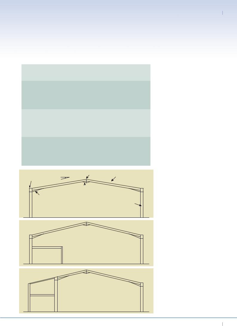
Pitched roof portal frame
One of the most common structures for industrial buildings is the single-span symmetrical portal frame, as shown in Figure 3.2. The following characteristics emerged as the most economical and can therefore be seen as a basis at an early design stage:
•Span between 15 m and 50 m
(25 to 35 m is the most efficient).
•Eaves height between 5 and 10 m
(5 to 6 m is the most efficient).
Portal frame structures
Column and beam structures
Secondary components and bracing
Connections
EURO-BUILD in Steel 15

03 Best Practice in Steel Construction - INDUSTriAL Buildings
Figure 3.1 Examples of out-of plane bracing of a portal frame
•Roof pitch between 5° and 10° (6° is commonly adopted).
•Frame spacing between 5 m and 8 m (the greater spacings being associated with the longer span portal frames).
•Haunches in the rafters at the eaves and if necessary at the apex.
Table 3.1 can be used as an aid for pre-design of single span portal frames. The use of haunches at the eaves and apex both reduces the required depth of rafter and achieves an efficient moment connection at these points. Often the haunch is cut from the same size of section as the rafter.
Portal frame with a mezzanine floor
Office accommodation is often provided within a portal frame structure using
a mezzanine floor (see Figure 3.3), which may be partial or full width.
Stiffening in two directions by using bracings in roof and walls as well as in gable
wall (roof cladding also provides in-place stiffness)
Stiffening in longitudinal direction by using bracings in roof and special bracings for integration of a door in the wall
Stiffening in longitudinal direction by using bracings in roof and walls with frame in gable wall for possible further expansion
Stiffening in longitudinal direction by using bracings in roof and portal frame in wall for integration of a door
It can be designed to stabilise the frame.
Often the internal floor requires additional fire protection.
Portal frame with external mezzanine
Offices may be located externally to the portal frame, creating an asymmetric portal structure, as shown in Figure 3.4. The main advantage of this framework is that large columns and haunches do not obstruct the office space. Generally, this additional structure depends on the portal frame for its stability.
Crane portal frame with column brackets
Cranes, if needed, have an important influence on the design and the dimensions of portal frames.
They create additional vertical loads
as well as considerable horizontal forces, which influence the size of the column section, in particular.
Where the crane is of relatively low capacity (up to about 20 tonnes), brackets can be fixed to the columns to support the crane (see Figure 3.5). Use of a tie member between haunches
across the building or fixed column bases may be necessary to reduce the relative eaves deflection. The outward movement of the frame at crane rail level may be of critical importance to the functioning of the crane.
For heavy cranes, it is appropriate to support the crane rails on additional columns, which may be tied to the portal frame columns by bracing in order to provide stability.
Propped portal frame
Where the span of a portal frame is greater than 30 m, and there is no need to provide a clear span, a propped portal frame (see Figure 3.6) can reduce the rafter size and also the horizontal forces
16 EURO-BUILD in Steel
Support Structures 03
|
Snow load |
Span |
Eaves |
Roof pitch |
Frame |
Required |
||
|
height |
spacing |
cross section |
|||||
|
[kN/m²] |
[m] |
[m] |
[°] |
[m] |
Column |
Rafter |
|
|
|
30.0 |
6.0 |
6.0 |
5.0 |
IPE 600 |
IPE 550 |
|
|
|
25.0 |
6.0 |
6.0 |
5.0 |
IPE 500 |
IPE 500 |
|
0.75 |
20.0 |
6.0 |
6.0 |
5.0 |
IPE 450 |
IPE 450 |
||
|
|
15.0 |
5.0 |
6.0 |
5.0 |
IPE 360 |
IPE 360 |
|
|
|
12.0 |
4.0 |
6.0 |
5.0 |
IPE 300 |
IPE 300 |
|
|
|
30.0 |
6.0 |
6.0 |
5.0 |
HEA 500 |
HEA 500 |
|
|
|
25.0 |
6.0 |
6.0 |
5.0 |
IPE 600 |
IPE 550 |
|
1.20 |
20.0 |
6.0 |
6.0 |
5.0 |
IPE 500 |
IPE 500 |
||
|
|
15.0 |
5.0 |
6.0 |
5.0 |
IPE 450 |
IPE 450 |
|
|
|
12.0 |
4.0 |
6.0 |
5.0 |
IPE 360 |
IPE 360 |
|
|
|
30.0 |
6.0 |
6.0 |
5.0 |
HEA 650 |
HEA 650 |
|
|
|
25.0 |
6.0 |
6.0 |
5.0 |
HEA 550 |
HEA 550 |
|
2.00 |
20.0 |
6.0 |
6.0 |
5.0 |
IPE 600 |
HEA 600 |
||
|
|
15.0 |
5.0 |
6.0 |
5.0 |
IPE 500 |
IPE 500 |
|
|
|
12.0 |
4.0 |
6.0 |
5.0 |
IPE 400 |
IPE 400 |
|
|
|
|
|
|
|
|
|
|
|
|
|
Roof pitch |
Apex |
|
Rafter |
|
|
|
|
|
|
|
|
|
||
Eaves
 Apex haunch
Eaves haunch
Column
Mezzanine
Mezzanine
Table 3.1 Pre-design table for portal frames
Figure 3.2 Single span symmetrical portal frame
Figure 3.3 Portal frame with internal mezzanine floor
Figure 3.4 Portal frame with external mezzanine floor
EURO-BUILD in Steel 17

03 Best Practice in Steel Construction - INDUSTriAL Buildings
 Column
bracket
Figure 3.5 Portal frame with column brackets
Possible location
* of out of plane restraint
Prop
Clear internal height
Figure 3.6 Propped portal frame
at the bases of the columns, thus leading to savings in both steelwork and foundation costs.
This type of frame is sometimes referred to as a ‘single span propped portal’, but it acts as a two-span portal frame in terms of the behaviour of the beam.
Tied portal frame
In a tied portal frame (see Figure 3.7), the horizontal movements of the eaves and the moments in the columns are reduced, at the cost of a reduction in the clear height. For roof slopes of less than 15°, large forces will develop in the rafters and the tie.
Mansard portal frame
A mansard portal frame consists of a series of rafters and haunches (as in Figure 3.8). It may be used where a large clear span is required but the eaves height of the building has to be minimised. A tied mansard may be an economic solution where there is a need to restrict eaves spread.
Curved rafter portal frame
Curved rafter portals (see Figure 3.9 and Figure 2.8) are often used for architectural
applications. The rafter can be curved to a radius by cold bending. For spans
greater than 16 m, splices may be required in the rafter because of limitations of transport. For architectural reasons, these splices may be designed to be visually unobtrusive.
Alternatively, where the roof must be curved but the frame need not be curved, the rafter can be fabricated as a series of straight elements.
Cellular portal frame
Cellular beams are commonly used in portal frames which have curved
rafters (see Figure 3.10 and Figure 2.9). Where splices are required in the rafter for transport, these should be detailed to preserve the architectural features for this form of construction.
Gable wall frames
Gable wall frames are located at the ends of the building and may comprise posts and simply-supported rafters rather than a full-span portal frame (see Figure 3.11). If the building is to be extended later,
a portal frame of the same size as the internal frames should be provided.
In cases in which the stability of the gable
wall is not provided by a portal frame, bracings or rigid panels are needed, as shown in Figure 3.11.
Column & beam structures
Column and beam structures require an independent bracing system in both directions. The beams may be I sections or lattice trusses.
Column & beam structures with hinged column bases
For simple beam and column structures, the columns are loaded mainly in compression which leads to smaller columns. Compared to a portal frame, the internal moments in the beam are greater, leading to larger steel sections. Since pinned connections are less complex than moment resisting connections, fabrication costs can be reduced. Table 3.2 gives some indicative column and beam sizes for a hinged column base.
For this type of support structure, bracings in both directions are required in the roof as well as in the walls in order to provide stability for horizontal loads. For that reason, it is often used for predominantly enclosed halls (i.e. no substantial openings). This fact also has
18 EURO-BUILD in Steel