

AIR TRAFFIC CONTROL
.pdf5 JUN 09 |
AIR TRAFFIC CONTROL |
241 |
FLIGHT PROCEDURES (DOC 8168) - HOLDING PROCEDURES
1HOLDING CRITERIA
1.1.1 To ensure that aircraft remain in the protecting holding areas, pilots shall use established error check procedures to reduce the effects of operating errors, data errors or equipment malfunction.
1.1.3 The procedures described in this chapter are related to right turn holding patterns. For left turn holding patterns, the corresponding entry and holding procedures are symmetrical with respect to the inbound holding track.
1.3.1Speeds
Holding patterns shall be entered and flown at or below the airspeeds given in Table I-6-1-1.
NOTE: The speeds in given in Table I-6-1-1 are rounded to the nearest multiple of five for operational reasons. From the standpoint of operational safety, these speeds are considered to be equivalent to the unrounded originals.
1.3.2Bank angle/rate of turn
All turns are to be made at a bank angle of 25° or at a rate of 3° per second, whichever requires the lesser bank.
1.3.3Allowance for known wind
All procedures depict tracks. Pilots should attempt to maintain the track by making allowance for known wind by applying corrections both to heading and timing. This should be done during entry and while flying in the holding pattern.
1.3.4Start of outbound timing
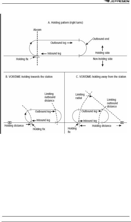
Outbound timing begins over or abeam the fix, whichever occurs later. If the abeam position cannot be determined, start timing when turn to outbound is completed.
1.3.5Outbound leg length based on a DME distance
If the outbound leg length is based on a DME distance, then the outbound leg terminates as soon as the limiting DME distance is reached.
1.3.6Limiting radials
1.3.6.1In the case of holding away from the station, where the distance from the holding fix to the VOR/DME station is short, a limiting radial may be specified. A limiting radial may also be specified where airspace conservation is essential.
1.3.6.2If the limiting radial is reached before the limiting DME distance, this radial should be followed until a turn inbound is initiated. The turn should be initiated at the latest where the limiting DME distance is reached.
1.3.7ATC notification
If for any reason a pilot is unable to conform to the procedures for normal conditions, air traffic control should be advised as early as possible.
1.4ENTRY
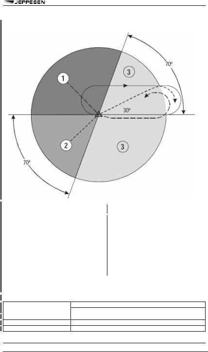
1.4.1 The entry into the holding pattern shall be according to heading in relation to the three entry sectors shown in Figure I-6-1-2, recognizing a zone of flexibility of 5° on either side of the sector boundaries.
1.4.2For holding on a VOR intersection, the entry track is limited to the radials forming the intersection.
1.4.3For holding on a VOR/DME fix, the entry track is limited to:
a.the VOR radial;
b.the DME arc; or
c.the entry radial to a VOR/DME fix at the end of the outbound leg, as published.
1.4.4Sector 1 entry
Sector 1 procedure (parallel entry):
a.at the fix, the aircraft is turned left onto an outbound heading for the appropriate period of time; then
b.the aircraft is turned left onto the holding side to intercept the inbound track or to return to the fix; and then
c.on second arrival over the holding fix, the aircraft is turned right to follow the holding pattern.
1.4.5 Sector 2 entry
Sector 2 procedure (offset entry):
a.at the fix, the aircraft is turned onto a heading to make good a track making an angle of 30° from the reciprocal of the inbound track on the holding side; then
b.the aircraft will fly outbound:
1.for the appropriate period of time (see 1.4.9, “Time/distance outbound”), where timing is specified; or
2.until the appropriate limiting DME distance is reached, where distance is specified. If a limiting radial is also specified, then the outbound distance is determined either by limiting DME distance or the limiting radial, whichever comes first;
c.the aircraft is turned right to intercept the inbound holding track; and
d.on second arrival over the holding fix, the aircraft is turned right to follow the holding pattern.
1.4.6Sector 3 entry
Sector 3 procedure (direct entry): Having reached the fix, the aircraft is turned right to follow the holding pattern.
1.4.7DME arc entry
DME arc entry: at the fix, the aircraft shall enter the holding pattern in accordance with either the Sector 1 or Sector 3 entry procedure.
1.4.8Special entry procedure for VOR/DME holding
NOTE: Where a special entry procedure is used, the entry radial is clearly depicted.
1.4.9Time/distance outbound
The still air time for flying the outbound entry heading should not exceed:
a.one minute if at or below 4250 m (14000 ft); or
b.one and one-half minutes if above 4250 m (14000 ft).
© JEPPESEN, 2002, 2009. ALL RIGHTS RESERVED.
242 AIR TRAFFIC CONTROL 5 JUN 09
FLIGHT PROCEDURES (DOC 8168) - HOLDING PROCEDURES
Where DME is available, the length of the outbound leg may be specified in terms of distance instead of time.
1.5.1Still air condition
a.Having entered the holding pattern, on the second and subsequent arrivals over the fix, the aircraft turns to fly an outbound track which will most appropriately position the aircraft for the turn onto the inbound track;
b.It continues outbound:
1.where timing is specified:
(a)for one minute if at or below 4250 m (14000 ft); or
(b)for one and one-half minutes if above 4250 m (14000 ft);
2.where distance is specified until the appropriate limiting DME distance is reached; then
c.the aircraft turns so as to realign itself on the inbound track.
1.5.2Corrections for wind effect
Due allowance should be made in both heading and timing to compensate for the effects of wind to ensure the inbound track is regained before passing the holding fix inbound. In making these corrections, full use should be made of the indications available from the navaid and estimated or known wind.
1.5.3Departing the pattern
When clearance is received specifying the time of departure from the holding point, the pilot should adjust the pattern within the limits of the established holding procedure in order to leave the holding point at the time specified.
520 km/h (280 kt) or
Table IV-1-2. PANS-OPS Second Edition Holding Speeds Applicable to Many of the Presently Published Holdings
Levels1 |
2 |
520 km/h
(280 kt) or
0.8 Mach whichever is less3
© JEPPESEN, 2002, 2009. ALL RIGHTS RESERVED.

5 JUN 09 |
AIR TRAFFIC CONTROL |
243 |
FLIGHT PROCEDURES (DOC 8168) - HOLDING PROCEDURES
Table IV-1-2. PANS-OPS Second Edition Holding Speeds Applicable to Many of the Presently Published Holdings (continued)
Levels1 |
2 |
© JEPPESEN, 2002, 2009. ALL RIGHTS RESERVED.
244 AIR TRAFFIC CONTROL 5 JUN 09
FLIGHT PROCEDURES (DOC 8168) - HOLDING PROCEDURES
Figure I-6-1-1. Shape and terminology associated with right turn holding pattern
© JEPPESEN, 2002, 2009. ALL RIGHTS RESERVED.
5 JUN 09 |
AIR TRAFFIC CONTROL |
245 |
FLIGHT PROCEDURES (DOC 8168) - HOLDING PROCEDURES
Figure I-6-1-2. Entry sectors
2OBSTACLE CLEARANCE
2.1HOLDING AREA
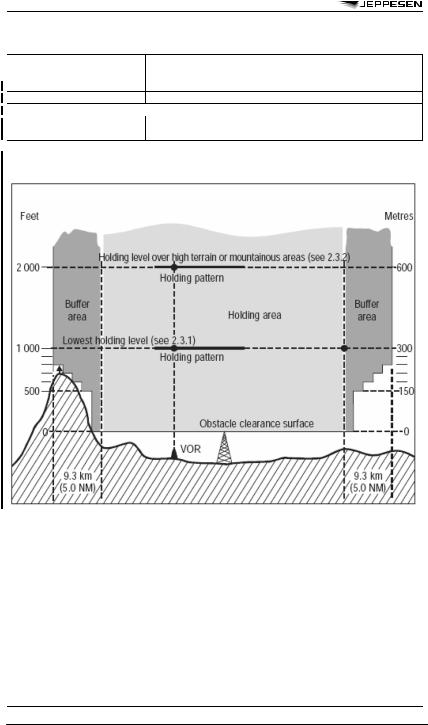
The holding area includes the basic holding area and the entry area. The basic holding area is the airspace required for a holding pattern at specified level, based on the allowances for aircraft speed, wind effect, timing errors, holding fix characteristics, etc. The entry area is the airspace required for the entry procedure.
2.2BUFFER AREA
An additional buffer area extends 9.3 km (5.0 NM) beyond the boundary of the holding area. Significant obstacles in the buffer area are taken into consideration when determining the minimum holding level.
2.3MINIMUM HOLDING LEVEL
2.3.1 The minimum permissible holding level (see Figure I-6-2-1) provides a clearance of at least:
a.300 m (984 ft) above obstacles in the holding area;
b.one of the values shown in Table I-6-2-1 above obstacles in the buffer area.
The minimum holding altitude to be published shall be rounded up to the nearest 50 m or 100 ft as appropriate.
2.3.2Obstacle clearance over high terrain or in mountainous areas
Over high terrain or in mountainous areas, additional obstacle clearance up to a total of 600 m (1969 ft) is provided to accommodate the possible effects of turbulence, down drafts and other meteorological phenomena on the performance of altimeters.
© JEPPESEN, 2002, 2009. ALL RIGHTS RESERVED.
246 AIR TRAFFIC CONTROL 5 JUN 09
FLIGHT PROCEDURES (DOC 8168) - HOLDING PROCEDURES
Table I-6-2-1. Obstacle clearance increment (continued) Distance beyond the boundary
Figure I-6-2-1. Minimum holding level as determined by the obstacle clearance surface related to the holding area and the buffer area
© JEPPESEN, 2002, 2009. ALL RIGHTS RESERVED.

5 JUN 09 |
AIR TRAFFIC CONTROL |
247 |
FLIGHT PROCEDURES (DOC 8168) - NOISE ABATEMENT PROCEDURES
1GENERAL NOISE ABATEMENT
INFORMATION
1.1Nothing in these procedures shall prevent the pilot-in-command from exercising authority for the safe operation of the aeroplane.
1.2Noise abatement procedures shall not be implemented except where a need for such procedures has been determined.
1.3The procedures herein describe the methods for noise abatement. They have been designed for application to turbojet aeroplanes. They can comprise any one or more of the following:
a.use of noise preferential runways to direct the initial and final flight paths of aeroplanes away from noise-sensitive areas;
b.use of noise preferential routes to assist aeroplanes in avoiding noise-sensitive areas on departure and arrival, including the use of turns to direct aeroplanes away from noise-sensitive areas located under or adjacent to the usual take-off and approach flight paths; and
c.use of noise abatement take-off or approach procedures, designed to minimize the overall exposure to noise on the ground and at the same time maintain the required levels of flight safety.
1.4For the purpose of these procedures, the heights given in metres and feet and speeds given in kilometers/hour and knots are considered to be operationally acceptable equivalents.
2NOISE PREFERENTIAL RUNWAYS AND ROUTES
2.1NOISE PREFERENTIAL RUNWAYS
2.1.1A runway for take-off or landing, appropriate to the operation, may be nominated for noise abatement purposes, the objective being to utilize whenever possible those runways that permit aeroplanes to avoid noise-sensitive areas during the initial departure and final approach phases of flight.
2.1.2Runways should not be selected for noise abatement purposes for landing operations unless they are equipped with suitable glide path guidance, e.g. ILS, or a visual approach slope indicator system for operations in visual meteorological conditions.
2.1.3A pilot-in-command prompted by safety concerns can refuse a runway offered for noise preferential reasons.
2.1.4Noise abatement shall not be determining factor in runway nomination under the following circumstances:
a.if the runway surface conditions are adversely affected (e.g. by snow, slush, ice, water, mud, rubber, oil or other substances);
b.for landing in conditions:
1.when the ceiling is lower than 150 m (500 ft) above aerodrome elevation or the visibility is less than (1900 m); or,
2.when the approach requires vertical minima greater than 100 m (300 ft) above aerodrome elevation and:
(a)the ceiling is lower than 240 m (800 ft) above aerodrome elevation; or
(b)the visibility is less than 3000 m;
c.for take-off when the visibility is less than 1900 m;
d.when wind shear has been reported or forecast or when thunderstorms are expected to affect the approach or departure;
e.when the crosswind component, including gusts, exceeds 28 km/h (15 ft), or the tailwind component, including gusts, exceeds 9 km/h (5 kt).
2.2NOISE PREFERENTIAL ROUTES
2.2.1Noise preferential routes are established to ensure that departing and arriving aeroplanes avoid over-flying noise-sensitive areas in the vicinity of the aerodrome as far as practicable.
2.2.2In establishing noise preferential routes:
a.turns during take-off and climb should not be required unless:
1.the aeroplane has reached (and can maintain throughout the turn) a height of not less than 150 m (500 ft) above terrain and the highest obstacles under the flight path;
2.the bank angle for turns after take-off is limited to 15° except where adequate provision is made for an acceleration phase permitting attainment of safe speeds for bank angles greater than 15°;
b. no turns should be required coincident with a reduction of power associated with a noise abatement procedure; and
c.sufficient navigation guidance should be provided to permit aeroplanes to adhere to the designated route.
2.2.3In establishing noise preferential routes, the safety criteria of standard departure and standard arrival routes regarding obstacle clearance climb gradients and other factors should be taken into full consideration.
2.2.4Where noise preferential routes are established, these routes and standard departure and arrival routes should be compatible.
2.2.5An aeroplane should not be diverted from its assigned route unless:
a.in the case of a departing aeroplane, it has attained the altitude or height which represents the upper limit for noise abatement procedures; or
b.it is necessary for the safety of the aeroplane (e.g. for avoidance of severe weather or to resolve a traffic conflict).
© JEPPESEN, 2002, 2009. ALL RIGHTS RESERVED.
248 AIR TRAFFIC CONTROL 5 JUN 09
FLIGHT PROCEDURES (DOC 8168) - NOISE ABATEMENT PROCEDURES
3AEROPLANE OPERATING PROCEDURES
3.1.2 The State in which the aerodrome is located is responsible for ensuring that aerodrome operators specify the location of noise sensitive areas and/or the location of noise monitors and their respective maximum allowable noise levels, if applicable. Aircraft operators are responsible for developing operating procedures in accordance with this chapter to meet the noise concerns of aerodrome operators. The approval of the aircraft operators’ procedures by the State of the Operator will ensure that the safety criteria contained in 3.3 of this chapter are met.
3.1.3 The appendix to this chapter contains two examples of noise abatement departure climb procedures. One example is designed to alleviate noise close to the aerodrome, and the other is designed to alleviate noise more distant from the aerodrome.
3.2.1General
The pilot-in-command has the authority to decide not to execute a noise abatement departure procedure if conditions preclude the safe execution of the procedure.
3.2.2Departure climb
Aeroplane operating procedures for the departure climb shall ensure that the safety of flight operations is maintained while minimizing exposure to noise on the ground. The following requirements need to be satisfied.
a.All necessary obstacle data shall be made available to the operator, and the procedure design gradient shall be observed.
b.Conduct of noise abatement climb procedures is secondary to meeting obstacle clearance requirements.
c.The power or thrust settings specified in the aircraft operating manual are to take account of the need for engine anti-icing when applicable.
d.The power or thrust settings to be used subsequent to the failure or shutdown of an engine or any other apparent loss of performance, at any stage in the take-off or noise abatement climb, are at the discretion of the pilot-in-command, and noise abatement considerations no longer apply.
e.Noise abatement climb procedures are not to be required in conditions where wind shear warnings exist, or the presence of wind shear or downburst activity is suspected.
f.The maximum acceptable body angle specified for an aeroplane type shall not be exceeded.
3.3DEVELOPMENT OF PROCEDURES
3.3.1 Noise abatement procedures shall be developed by the aircraft operator for each aeroplane type (with advice from the aeroplane manufacturer, as needed) and approved by the State of the Operator complying at a minimum with the following safety criteria.
a.Initial power or thrust reductions shall not be executed below a height of 240 m (800 ft) above the aerodrome elevation.
b.The level of power or thrust for the flap/slat configuration, after power or thrust reduction, shall not be less than:
1.for aeroplanes in which derated take-off thrust and climb thrust are computed by the flight management system, the computed climb power/thrust; or
2.for other aeroplanes, normal climb power/ thrust.
3.3.2To minimize the impact on training while maintaining flexibility to address variations in the location of noise sensitive areas, the aeroplane operator shall develop no more than two noise abatement procedures for each aeroplane type. It is recommended that one procedure should provide noise benefits for areas close to the aerodrome, and the other for areas more distant from the aerodrome.
3.3.3Any difference of power or thrust reduction initiation height for noise abatement purposes constitutes a new procedure.
3.4AEROPLANE OPERATING PROCEDURES — APPROACH
3.4.1 In noise abatement approach procedures which are developed:
a.the aeroplane shall not be required to be in any configuration other than the final landing configuration at any point after passing the outer marker or 5 NM from the threshold of the runway of intended landing, whichever is earlier; and
b.excessive rates of descent shall not be required.
3.4.2 When it is necessary to develop a noise abatement approach procedure based on currently available (1982) systems and equipment, the following safety considerations shall be take fully into account:
a.glide path or approach angles should not require an approach to be made:
1.above the ILS glide path angle;
2.above the glide path of the visual approach slope indicator system;
3.above the normal PAR final approach angle; and
4.above an angle of 3° except where it has been necessary to establish, for operational purposes, an ILS with a glide path angle greater than 3°;
b.the pilot should not be required to complete a turn on to final approach at distances less than will:
1.in the case of visual operations, permit an adequate period of stabilized flight on final approach before crossing the runway threshold; or
© JEPPESEN, 2002, 2009. ALL RIGHTS RESERVED.

5 JUN 09 |
AIR TRAFFIC CONTROL |
249 |
FLIGHT PROCEDURES (DOC 8168) - NOISE ABATEMENT PROCEDURES
2.in the case of instrument approaches, permit the aircraft to be established on final approach prior to interception of the glide path.
3.4.4Compliance with published noise abatement approach procedures should not be required in adverse operating conditions such as:
a.if the runway is not clear and dry, i.e. it is adversely affected by snow, slush, ice or water, mud, rubber, oil or other substances;
b.in conditions when the ceiling is lower than 150 m (500 ft) above aerodrome elevation, or when the horizontal visibility is less than 1.9 km (1 NM);
c.when the crosswind component, including gusts, exceeds 28 km/h (15 kt);
d.when the tailwind component, including gusts, exceeds 9 km/h (5 kt); and
e.when wind shear has been reported or forecast or when adverse weather conditions, e.g. thunderstorms, are expected to affect the approach.
3.5AEROPLANE OPERATING PROCEDURES — LANDING
Noise abatement procedures shall not contain a prohibition of use of reverse thrust during landing.
3.6DISPLACED THRESHOLDS
The practice of using a displaced runway threshold as a noise abatement measure shall not be employed unless aircraft noise is significantly reduced by such use and the runway length remaining is safe and sufficient for all operational requirements.
3.7CONFIGURATION AND SPEED CHANGES
Deviations from normal configuration and speeds appropriate to the phase of flight shall not be made mandatory.
3.8UPPER LIMIT
Noise abatement procedures shall include information on the altitude/height above which they are no longer applicable.
3.9COMMUNICATIONS
In order not to distract flight crews during the execution of noise abatement procedures, air/ground communications should be kept to a minimum.
Appendix to Chapter 3 — NOISE ABATEMENT DEPARTURE CLIMB GUIDANCE
1General
1.1 Aeroplane operating procedures for the departure climb shall ensure that the necessary safety of flight operations is maintained while minimizing exposure to noise on the ground. These procedures are provided as examples because the noise reductions obtained depend greatly on the type of aeroplane, engine type, thrust required, and the height at which thrust is reduced. For this reason, procedures that provide the best possible noise ben-
efit may differ significantly from one aeroplane type to another, and between aeroplanes of the same type with different engines.
States should avoid the practice of requiring all operators to use one of the example procedures for departures from specific runways, and should instead allow aircraft operators to develop operational procedures that maximize the noise benefits obtainable from their aeroplanes. This is not intended to prevent States from suggesting the use of a procedure based on one of the examples, as an alternative to operator-spe- cific procedures. The following two examples of operating procedures for the climb have been developed as guidance and are considered safe when the criteria in 3.2.2 are satisfied.
The first example (NADP 1) is intended to describe one method, but not the only method, of providing noise reduction for noise-sensitive areas in close proximity to the departure end of the runway (see Figure I-7-3-App-1).
The second example (NADP 2) similarly describes one method, but not the only method, of providing noise reduction to areas more distant from the runway end (see Figure I-7-3-App-2). Aircraft operators may find that to suit their particular route system (i.e. at aerodromes where they operate), two different procedures, one designed for close and the other designed for distant noise reduction, may be appropriate.
1.2 The two example procedures differ in that the acceleration segment for flap/slat retraction is either initiated prior to reaching the maximum prescribed height or at the maximum prescribed height. To ensure optimum acceleration performance, power or thrust reduction may be initiated at an intermediate flap setting.
2Noise abatement departure climb — Example of a procedure alleviating noise close to the
aerodrome (NADP 1)
2.1 This procedure involves a power or thrust reduction at or above the prescribed minimum altitude (240 m/800 ft above aerodrome elevation) and the delay of flap/slat retraction until the prescribed maximum altitude is attained. At the prescribed maximum altitude (900 m/3000 ft above aerodrome elevation), the aircraft is accelerated and the flaps/slats are retracted on schedule while maintaining a positive rate of climb, to complete the transition to normal en-route climb speed. The initial climbing speed to the noise abatement initiation point is not less than V2 plus 20 km/h (V2 plus 10 kt).
© JEPPESEN, 2002, 2009. ALL RIGHTS RESERVED.

250 AIR TRAFFIC CONTROL 5 JUN 09
FLIGHT PROCEDURES (DOC 8168) - NOISE ABATEMENT PROCEDURES
2.2 In the example shown below, on reaching an altitude of 240 m/800 ft above aerodrome elevation, engine power or thrust is adjusted in accordance with the noise abatement power thrust schedule provided in the aircraft operating manual. A climb speed of V2 plus 20 to 40 km/h ( V2 plus 10 to 20 kt) is maintained with flaps and slats in the take-off configuration. On reaching an altitude of 900 m/3000 ft above aerodrome elevation, the aircraft is accelerated and the flaps/slats are retracted on schedule while maintaining a positive rate of climb to complete the transition to normal en-route climb speed.
3Noise abatement departure climb — Example of a procedure alleviating noise distant from
the aerodrome (NADP 2)
3.1This procedure involves initiation of flap/slat retraction at or above the prescribed minimum altitude (240 m/800 ft above aerodrome elevation) but before reaching the prescribed maximum altitude (900 m/3000 ft above aerodrome elevation). The flaps/slats are to be retracted on schedule while maintaining a positive rate of climb. Intermediate flap retraction, if required for performance, may be accomplished below the prescribed minimum altitude. The power or thrust reduction is initiated at a point along the acceleration segment that ensures satisfactory acceleration performance. At the prescribed maximum altitude, a transition is made to normal en-route climb procedures. The initial climbing speed to the noise abatement initiation point is not less than V2 plus 20 km/h (V2 plus 10kt).
3.2In the example shown below, on reaching 240 m/800 ft above aerodrome elevation, the aircraft body angle/angle of pitch is decreased, the aero-
plane is accelerated towards Vzf , and the flaps/slats are retracted on schedule. Power or thrust reduction is initiated at a point along the acceleration segment that ensures satisfactory acceleration performance. A positive rate of climb is maintained to 900 m/3000 ft above aerodrome elevation. On reaching this altitude, a transition is made to normal en-route climb speed.
3.3An aeroplane should not be diverted from its assigned route unless:
a.in the case of a departing aeroplane it has attained the altitude or height which represents the upper limit for noise abatement procedures; or
b.it is necessary for the safety of the aeroplane (e.g. for avoidance of severe weather or to resolve a traffic conflict).
© JEPPESEN, 2002, 2009. ALL RIGHTS RESERVED.