

AIR TRAFFIC CONTROL
.pdf5 JUN 09 |
AIR TRAFFIC CONTROL |
277 |
FLIGHT PROCEDURES (DOC 8168) - ENROUTE
1AREA NAVIGATION (RNAV) AND RNP-BASED EN-ROUTE PROCEDURES
1.1STANDARD CONDITIONS
1.1.1The general criteria for VOR and NDB routes apply except that the area has a constant width and no angular limits.
1.1.2The standard assumptions on which enroute RNAV/RNP procedures are developed are:
a.the fix tolerance area of the waypoint is a circle of radius equal to the enroute RNP;
b.the system provides information which the pilot monitors and uses to intervene and thus limit excursions of the FTT to values within those taken into account during the system certification process; and
c.enroute procedures are normally based on RNP 4 or higher. Where necessary and appropriate, they may be based on RNP 1.
1.2DEFINITION OF TURNS
1.2.1Turns in an RNAV route only allow the use of fly-by waypoints.
1.2.2There are two kinds of turns for RNP
routes:
a.the turn at a fly-by waypoint ; and
b.the controlled turn. For this kind of turn, used on RNP 1 routes, the radius of turn is:
1.28 km (15 NM) at and below FL 190; and
2.41.7 km (22.5 NM) at and above FL 200.
© JEPPESEN, 2002, 2009. ALL RIGHTS RESERVED.

5 JUN 09 |
AIR TRAFFIC CONTROL |
279 |
AIRCRAFT OPERATING PROCEDURES - ALTIMETER SETTING PROCEDURES
1INTRODUCTION TO ALTIMETER
SETTING PROCEDURES
1.1 These procedures describe the method for providing adequate vertical separation between aircraft and for providing adequate terrain clearance during all phases of a flight. This method is based on the following basic principles:
a.States may specify a fixed altitude known as the transition altitude. In flight, when an aircraft is at or below the transition altitude, its vertical position is expressed in terms of altitude, which is determined from an altimeter set to sea level pressure (QNH).
b.In flight above the transition altitude, the vertical position of an aircraft is expressed in terms of flight levels, which are surfaces of constant atmospheric pressure based on an altimeter setting of 1013.2 hPa.
c.The change in reference from altitude to flight levels, and vice versa, is made:
1.at the transition altitude, when climbing; and
2.at the transition level, when descending.
d.The transition level may be nearly coincident with the transition altitude to maximize the number of flight levels available. Alternatively, the transition level may be located 300 m (or 1000 ft) above the transition altitude to permit the transition altitude and the transition level to be used concurrently in cruising flight, with vertical separation ensured. The airspace between the transition level and the transition altitude is called the transition layer.
e.Where no transition altitude has been established for the area, aircraft in the en-route phase shall be flown at a flight level.
f.The adequacy of terrain clearance during any phase of a flight may be maintained in any of several ways, depending upon the facilities available in a particular area. The recommended methods in the order of preference are:
1.the use of current QNH reports from an adequate network of QNH reporting stations;
2.the use of such QNH reports as are available, combined with other meteorological information such as forecast lowest mean sea level pressure for the route or portions thereof; and
3.where relevant current information is not available, the use of values of the lowest altitudes or flight levels, derived from climatological data.
g.During the approach to land, terrain clearance may be determined by using:
1.the QNH altimeter setting (giving altitude); or
2.under specified circumstances a QFE setting (giving height above the QFE datum).
1.3These procedures apply to all IFR flights and to other flights which are operating at specific cruising levels in accordance with Annex 2 — Rules of the Air
or the Procedures for Air Navigation Services — Air Traffic Management (PANS-ATM, Doc 4444) or the Regional Supplementary Procedures (Doc 7030).
2BASIC ALTIMETER SETTING REQUIREMENTS
2.1.1System of flight levels
2.1.1.1 Flight level zero shall be located at the atmospheric pressure level of 1013.2 hPa. Consecutive flight levels shall be separated by a pressure interval corresponding to at least 500 ft (152.4 m) in the standard atmosphere.
2.1.2Transition altitude
2.1.2.1A transition altitude shall normally be specified for each aerodrome by the State in which the aerodrome is located.
2.1.2.2Where two or more closely spaced aerodromes are located so that coordinated procedures are required, a common transition altitude shall be established. This common transition altitude shall be the highest that would be required if the aerodromes were considered separately.
2.1.2.4The height above the aerodrome of the transition altitude shall be as low as possible but normally not less than 900 m (3000 ft).
2.1.2.5The calculated height of the transition altitude shall be rounded up to the next full 300 m (1000 ft).
2.1.2.7 Transition altitudes shall be published in aeronautical information publications and shown on the appropriate charts.
2.1.3Transition level
2.1.3.1States shall make provision for the determination of the transition level to be used at any given time at each of their aerodromes.
2.1.3.2Where two or more closely spaced aerodromes are located so that coordinated procedures and a common transition altitude are required, a common transition level shall also be used at those aerodromes.
2.1.4References to vertical position
2.1.4.1 The vertical position of aircraft operating at or below the transition altitude shall be expressed in terms of altitude. Vertical position at or above the transition level shall be expressed in terms of flight levels. This terminology applies during:
a.climb;
b.en-route flight; and
c.approach and landing
2.1.4.2Passing through the transition layer
While passing through the transition layer, vertical position shall be expressed in terms of:
a.flight levels when climbing; and
b.altitude when descending.
2.2TAKE-OFF AND CLIMB
A QNH altimeter setting shall be made available to aircraft in taxi clearance prior to take-off.
© JEPPESEN, 2002, 2009. ALL RIGHTS RESERVED.

280 AIR TRAFFIC CONTROL 5 JUN 09
AIRCRAFT OPERATING PROCEDURES - ALTIMETER SETTING PROCEDURES
2.3ENROUTE
2.3.2Terrain clearance
2.3.2.1QNH altimeter setting reports should be provided from sufficient locations to permit determination of terrain clearance with an acceptable degree of accuracy.
2.3.2.2For areas where adequate QNH altimeter setting reports cannot be provided, the appropriate authorities shall provide the information required to determine the lowest flight level which will ensure adequate terrain clearance. This information shall be made available in the most usable form.
2.4APPROACH AND LANDING
2.4.1The QNH altimeter setting shall be made available to aircraft in approach clearances and in clearances to enter the traffic circuit.
2.4.2A QFE altimeter setting, clearly identified as such, should be made available in approach and landing clearances. This should be available on request or on a regular basis, in accordance with local arrangements.
2.4.3References to vertical positioning after approach clearance
After approach clearance has been issued and the descent to land is begun, the vertical positioning of an aircraft above the transition level may be by reference to altitudes (QNH) provided that level flight above the transition altitude is not indicated or anticipated.
2.5MISSED APPROACH
The relevant parts of 2.2, “Take-off and climb”, 2.3, “Enroute”, and 2.4, “Approach and landing” shall apply in the event of a missed approach.
3PROCEDURES FOR OPERATORS AND PILOTS
3.1FLIGHT PLANNING
3.1.1 The levels at which a flight is to be conducted shall be specified in a flight plan:
a.as flight levels if the flight is to be conducted at or above the transition level (or the lowest usable flight level, if applicable); and
b.as altitudes if the flight is to be conducted at or below the transition altitude.
3.2PRE-FLIGHT OPERATIONAL TEST
The following test should be carried out in an aircraft by flight crew members before flight. Flight crews should be advised of the purpose of the test and the manner in which it should be carried out. They should also be given specific instructions on the action to be taken based on the test results.
QNH Setting
a.With the aircraft at a known elevation on the aerodrome, set the altimeter pressure scale to the current QNH setting.
b.Vibrate the instrument by tapping unless mechanical vibration is provided. A serviceable altimeter indicates the elevation of the point selected, plus the height of the altimeter above this point, within a tolerance of:
1.±20 m or 60 ft for altimeters with a test range of 0 to 9000 m (0 to 30000 ft); and
2.±25 m or 80 ft for altimeters with a test range of 0 to 15000 m (0 to 50000 ft).
QFE Setting
a.With the aircraft at a known elevation on the aerodrome, set the altimeter pressure scale to the current QFE setting.
b.Vibrate the instrument by tapping unless mechanical vibration is provided. A serviceable altimeter indicates the height of the altimeter in relation to the QFE reference point, within a tolerance of:
1.±20 m or 60 ft for altimeters with a test range of 0 to 9000 m (0 to 30000 ft); and
2.±25 m or 80 ft for altimeters with a test range of 0 to 15000 m (0 to 50000 ft).
3.3TAKE-OFF AND CLIMB
3.3.1Before taking off, one altimeter shall be set on the latest QNH altimeter setting for the aerodrome.
3.3.2During climb to, and while at the transition altitude, references to the vertical position of the aircraft in air-ground communications shall be expressed in terms of altitudes.
3.3.3On climbing through the transition altitude, the reference for the vertical position of the aircraft shall be changed from altitudes (QNH) to flight levels (1013.2 hPa), and thereafter the vertical position shall be expressed in terms of flight levels.
3.4ENROUTE
3.4.1Vertical separation
3.4.1.1 |
During enroute flight at or below |
the transition |
altitude, an aircraft shall be flown |
at altitudes. References to the vertical position of the aircraft in air-ground communications shall be expressed in terms of altitudes.
3.4.1.2 During enroute flight at or above transition levels or the lowest usable flight level, whichever is applicable, an aircraft shall be flown at flight levels. References to the vertical position of the aircraft in air-ground-communications shall be expressed in terms of flight levels.
3.5APPROACH AND LANDING
3.5.1Before beginning the initial approach to an aerodrome, the number of the transition level shall be obtained.
3.5.2Before descending below the transition level, the latest QNH altimeter setting for the aerodrome shall be obtained.
© JEPPESEN, 2002, 2009. ALL RIGHTS RESERVED.
5 JUN 09 |
AIR TRAFFIC CONTROL |
281 |
AIRCRAFT OPERATING PROCEDURES - ALTIMETER SETTING PROCEDURES
3.5.3As the aircraft descends through the tranthe lowest usable flight level is the responsibility of
sition level, the reference for the vertical position of the aircraft shall be changed from flight levels (1013.2 hPa) to altitudes (QNH). From this point on, the vertical position of the aircraft shall be expressed in terms of altitudes.
the pilot-in-command. Current or forecast QNH and temperature values should be taken into account.
4.1.5.2 It is possible that altimeter corrections below controlled airspace may accumulate to the point where the aircraft’s position may impinge on a
3.5.4When an aircraft which has been given a flight level or assigned altitude in controlled airspace.
clearance as number one to land is completing its approach using QFE, the vertical position of the aircraft shall be expressed in terms of the height above the aerodrome datum which was used in establishing obstacle clearance height (OCH). All subsequent references to vertical position shall be made in terms of height.
4ALTIMETER CORRECTIONS
NOTE: This chapter deals with altimeter corrections for pressure, temperature and, where appropriate, wind and terrain effects. The pilot is responsible for these corrections except when under radar vectoring. In that case, the radar controller issues clearances such that the prescribed obstacle clearance will exist at all times, taking the cold temperature correction into account.
4.1.1Pilot’s responsibility
The pilot-in-command must then obtain clearance from the appropriate control agency.
4.2PRESSURE CORRECTION
4.2.1Flight levels
When flying at levels with the altimeter set to 1013.2 hPa, the minimum safe altitude must be corrected for deviations in pressure when the pressure is lower than the standard atmosphere (1013 hPa). An appropriate correction is 10 m (30 ft) per hPa below 1013 hPa. Alternatively, the correction can be obtained from standard correction graphs or tables supplied by the operator.
4.2.2QNH/QFE
When using the QNH or QFE altimeter setting (giving altitude or height above QFE datum respectively), a pressure correction is not required.
The pilot-in-command is responsible for the safety of the operation and the safety of the aeroplane and of all persons on board during flight time (Annex 6, 4.5.1). This includes responsibility for obstacle clearance, except when an IFR flight is being vectored by radar.
4.1.2Operator’s responsibility
The operator is responsible for establishing minimum flight altitudes, which may not be less than those established by States that are flown over (Annex 6, 4.2.6). The operator is responsible for specifying a method for determining these minimum altitudes (Annex 6, 4.2.6). Annex 6 recommends that the method should be approved by the State of the Operator and also recommends the factors to be taken into account.
4.1.3State’s responsibility
Annex 15, Appendix 1 (Contents of Aeronautical Information Publication), indicates that States should publish in Section GEN 3.3.5, “The criteria used to determine minimum flight altitudes”. If nothing is published, it should be assumed that no corrections have been applied by the State.
4.1.4Air traffic control (ATC)
If an aircraft is cleared by ATC to an altitude which the pilot-in-command finds unacceptable due to low temperature, then the pilot-in-command should request a higher altitude. If such a request is not received, ATC will consider that the clearance has been accepted and will be complied with.
4.1.5Flights outside controlled airspace
4.1.5.1 For IFR flights outside controlled airspace, including flights operating below the lower limit of controlled airspace, the determination of
4.3TEMPERATURE CORRECTION
4.3.1Requirement for temperature correction
The calculated minimum safe altitudes/heights must be adjusted when the ambient temperature on the surface is much lower than that predicted by the standard atmosphere. In such conditions, an approximate correction is 4 per cent height increase for every 10°C below standard temperature as measured at the altimeter setting source. This is safe for all altimeter setting source altitudes for temperatures above -15°C.
4.3.2Tabulated corrections
For colder temperatures, a more accurate correction should be obtained from Tables III-1-4-1 a) and III-1-4-1 b). These tables are calculated for a sea level aerodrome. They are therefore conservative when applied at higher aerodromes.
4.3.4Accurate corrections
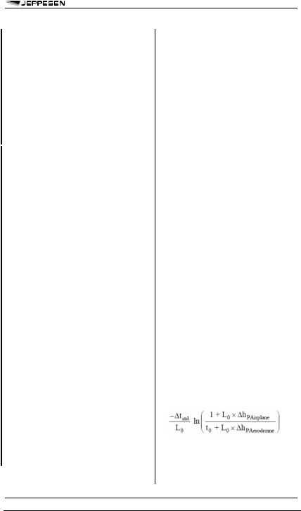
4.3.4.1 For occasions when a more accurate temperature correction is required, this may be obtained from Equation 24 of the Engineering Sciences Data Unit (ESDU) publication, Performance, Volume 2, Item Number 7702. This assumes an off-standard atmosphere.
where:
 hPAirplane = aircraft height above aerodrome (pressure)
 hGAirplane = aircraft height above aerodrome (geopotential)
© JEPPESEN, 2002, 2009. ALL RIGHTS RESERVED.

282 |
AIR TRAFFIC CONTROL 5 JUN 09 |
AIRCRAFT OPERATING PROCEDURES - ALTIMETER SETTING PROCEDURES
 tstd = temperature deviation from the International Standard Atmosphere (ISA) temperature
L0 = standard temperature lapse rate with pressure altitude in the first layer (sea level to tropopause) of the ISA
t0 = standard temperature at sea level
4.3.6Small corrections
For practical operational use, it is appropriate to apply a temperature correction when the value of the correction exceeds 20 per cent of the associated minimum obstacle clearance (MOC).
4.4MOUNTAINOUS AREAS – ENROUTE
The MOC over mountainous areas is normally applied during the design of routes and is stated in State aeronautical information publications. However, where no information is available, the margins in Tables III-1-4-2 and III-1-4-3 may be used when:
a.the selected cruising altitude or flight level or one engine inoperative stabilizing altitude is at or close to the calculated minimum safe altitude; and
b.the flight is within 19 km (10 NM) of terrain having a maximum elevation exceeding 900 m (3000 ft).
4.5MOUNTAINOUS TERRAIN – TERMINAL AREAS
4.5.1The combination of strong winds and mountainous terrain can cause local changes in atmospheric pressure due to the Bernoulli effect. This occurs particularly when the wind direction is across mountain crests or ridges. It is not possible to make an exact calculation, but theoretical studies (CFD Norway, Report 109.1989) have indicated altimeter errors as shown in Tables III-1-4-4 and III-1-4-5. Although States may provide guidance, it is up to the pilot-in-command to evaluate whether the combination of terrain, wind strength and direction are such as to make a correction for wind necessary.
4.5.2Corrections for wind speed should be applied in addition to the standard corrections for pressure and temperature, and ATC should be advised.
© JEPPESEN, 2002, 2009. ALL RIGHTS RESERVED.

5 JUN 09 |
AIR TRAFFIC CONTROL |
283 |
AIRCRAFT OPERATING PROCEDURES - SIMULTANEOUS OPERATIONS ON PARALLEL OR NEAR-PARALLEL INSTRUMENT RUNWAYS
1 |
MODES OF OPERATION |
1.3 |
EQUIPMENT REQUIREMENTS |
1.2 |
MODES OF OPERATION |
1.3.1 |
Airborne avionics |
1.2.1There can be a variety of modes of operaNormal instrument flight rules (IFR) avionics including
tion associated with the use of parallel or near-parallel instrument runways.
1.2.1.1 Modes One and Two — Simultaneous parallel instrument approaches
There are two basic modes of operation for approaches made to parallel runways:
a.Mode 1, Independent parallel approaches: In this mode, radar separation minima between aircraft using adjacent ILS and/or MLS are not prescribed; and
b.Mode 2, Dependent parallel approaches: In this mode, radar separation minima between aircraft using adjacent ILS and/or MLS are prescribed.
1.2.1.2 Mode 3 — Simultaneous instrument departures
Mode 3, Independent parallel departures: In this mode, aircraft are departing in the same direction from parallel runways simultaneously.
1.2.1.3 Mode 4 — Segregated parallel approaches/departures
Mode 4, Segregated parallel operations: In this mode, one runway is used for approaches, and one runway is used for departures.
1.2.1.4Semi-mixed and mixed operations
1.2.1.4.1 In the case of parallel approaches and departures, there may be semi-mixed operations. In this scenario:
a.one runway is used exclusively for departures, while the other runway accepts a mixture of approaches and departures; or
b.one runway is used exclusively for approaches while the other runway accepts a mixture of approaches and departures.
1.2.1.4.2 There may also be mixed operations, i.e. simultaneous parallel approaches with departures interspersed on both runways.
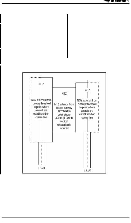
1.2.2.1Normal operating zone (NOZ)
1.2.2.1.1 This is airspace of defined dimensions extending to either side of an ILS localizer course and/or MLS final approach track centre line. It extends from the runway threshold to the point where aircraft are established on the centre line.
1.2.2.2No transgression zone (NTZ)
In the context of independent parallel approaches, this is a corridor of airspace at least 610 m (2000 ft) wide located centrally between the two extended runway centre lines. It extends from the nearer runway threshold to the point where 300 m (1000 ft) vertical separation is reduced. Penetration of the NTZ by an aircraft requires a controller intervention to manoeuvre any threatened aircraft on the adjacent approach.
full ILS or MLS capability are required for conducting parallel approaches.
1.5VECTORING TO THE ILS LOCALIZER COURSE OR MLS FINAL APPROACH TRACK
1.5.1 When simultaneous independent parallel approaches are in progress, the following apply:
a.The main objective is that both aircraft be established on the ILS localizer course or MLS final approach track before the 300 m (1000 ft) vertical separation is reduced; and
b.All approaches regardless of weather conditions shall be radar-monitored. Control instructions and information necessary to ensure separation between aircraft and to ensure that aircraft do not enter the NTZ shall be issued. The air traffic control procedure will be to vector arriving aircraft to one or the other of the parallel ILS localizer courses and/or the MLS final approach tracks. When cleared for an ILS or MLS approach, a procedure turn is not permitted.
c.When vectoring to intercept the ILS localizer course or MLS final approach track, the final vector shall be such as to:
1.allow the aircraft to intercept the ILS localizer course or MLS final approach track at an angle not greater than 30 degrees; and
2.provide at least 2 km (1.0 NM) straight and level flight prior to ILS localizer course or MLS final approach track intercept. The vector shall also be such as to enable the aircraft to be established on the ILS localizer course or MLS final approach track in level flight for at least 3.7 km (2.0 NM) prior to intercepting the ILS glide path or specified MLS elevation angle.
d.Each pair of parallel approaches will have a “high side” and a “low side” for vectoring, to provide vertical separation until aircraft are established inbound on their respective parallel ILS localizer course and/or MLS final approach track. The low side altitude will normally be such that the aircraft will be established on the ILS localizer course or MLS final approach track well before ILS glide path or specified MLS elevation angle interception. The high side altitude will be
300m (1000 ft) above the low side.
e.When the aircraft is assigned its final heading to intercept the ILS localizer course or MLS final approach track, it shall be advised of:
1.its final heading to intercept the ILS localizer course (or MLS final approach track);
2.the altitude to be maintained until both:
(a)the aircraft is established on the ILS localizer centre line (or MLS final approach track); and
© JEPPESEN, 2002, 2009. ALL RIGHTS RESERVED.
284 AIR TRAFFIC CONTROL 5 JUN 09
AIRCRAFT OPERATING PROCEDURES - SIMULTANEOUS OPERATIONS ON
PARALLEL OR NEAR-PARALLEL INSTRUMENT RUNWAYS
(b)the aircraft has reached the ILS glide path (or specified MLS elevation angle) intercept point; and
3.if required, clearance for the final approach.
f.If an aircraft is observed to overshoot the ILS localizer course or MLS final approach track during turn-to-final, the aircraft will be instructed to return immediately to the correct track. Pilots are not required to acknowledge these transmissions or subsequent instructions while on final approach unless requested to do so.
g.Once the 300 m (1000 ft) vertical separation is reduced, the radar controller monitoring the approach will issue control instructions if the aircraft deviates substantially from the ILS localizer course or MLS final approach track.
h.If an aircraft that deviates substantially from the ILS localizer course (or MLS final approach track) fails to take corrective action and penetrates the NTZ, the aircraft on the adjacent ILS localizer course (or MLS final approach track) will be instructed to immediately climb and turn to the assigned altitude and heading in order to avoid the deviating aircraft.
1.7TRACK DIVERGENCE
Simultaneous parallel operations require diverging tracks for missed approach procedures and departures. When turns are prescribed to establish divergence, pilots shall begin the turns as soon as practicable.
Figure III-2-1-1. Example of normal operating zones (NOZs) and no transgression zone (NTZ)
© JEPPESEN, 2002, 2009. ALL RIGHTS RESERVED.

5 JUN 09 |
AIR TRAFFIC CONTROL |
285 |
AIRCRAFT OPERATING PROCEDURES - SECONDARY SURVEILLANCE RADAR
(SSR) TRANSPONDER OPERATING PROCEDURES
1OPERATION OF TRANSPONDERS
1.1GENERAL
1.1.1 When an aircraft carries a serviceable transponder, the pilot shall operate the transponder at all times during flight, regardless of whether the aircraft is within or outside airspace where secondary surveillance radar (SSR) is used for ATS purposes.
1.1.3 When the aircraft carries serviceable Mode C equipment, the pilot shall continuously operate this mode, unless otherwise directed by ATC.
1.1.5 When requested by ATC to “CONFIRM SQUAWK [code]” the pilot shall:
a.verify the Mode A code setting on the transponder;
b.reselect the assigned code if necessary; and
c.confirm to ATC the setting displayed on the controls of the transponder.
1.1.6 Pilots shall not SQUAWK IDENT unless requested by ATC.
1.2USE OF MODE C
Whenever Mode C is operated, pilots shall, in air-ground voice communications where level information is required, give such information by stating their level to the nearest full 30 m or 100 ft as indicated on the pilot’s altimeter.
1.3USE OF MODE S
Pilots of aircraft equipped with Mode S having an aircraft identification feature shall set the aircraft identification in the transponder. This setting shall correspond to the aircraft identification specified in item 7 of the ICAO flight plan, or, if no flight plan has been filed, the aircraft registration.
1.7TRANSPONDER FAILURE PROCEDURES WHEN THE CARRIAGE OF A FUNCTIONING TRANSPONDER IS MANDATORY
1.7.1 In case of a transponder failure after departure, ATC units shall attempt to provide for continuation of the flight to the destination aerodrome in accordance with the flight plan. Pilots may, however, expect to comply with specific restrictions.
2PHRASEOLOGY
2.2PHRASEOLOGY USED BY PILOTS
Pilots shall read back the mode and code to be set when they acknowledge mode/code setting instructions.
a warning that an RA may follow. TAs indicate the approximate positions of intruding aircraft that may later cause resolution advisories. RAs propose vertical manoeuvres that are predicted to increase or maintain separation from threatening aircraft. ACAS I equipment is only capable of providing TAs, while ACAS II is capable of providing both TAs and RAs. In this chapter, reference to ACAS means ACAS II.
3.1.2ACAS indications shall be used by pilots in the avoidance of potential collisions, the enhancement of situational awareness, and the active search for, and visual acquisition of, conflicting traffic.
3.1.3Nothing in the procedures specified in 3.2 hereunder shall prevent pilots-in-command from exercising their best judgment and full authority in the choice of the best course of action to resolve a traffic conflict or avert a potential collision.
3.2USE OF ACAS INDICATIONS
The indications generated by ACAS shall be used by pilots in conformity with the following safety considerations:
a.pilots shall not maneuver their aircraft in response to traffic advisories (TAs) only;
b.on receipt of a TA, pilots shall use all available information to prepare for appropriate action if an RA occurs; and
c.in the event of an RA, pilots shall:
1.respond immediately by following the RA as indicated, unless doing so would jeopardize the safety of the aeroplane;
2.follow the RA even if there is a conflict between the RA and an air traffic control (ATC) instruction to manoeuvre;
3.not manoeuvre in the opposite sense to an RA;
4.as soon as possible, as permitted by flight crew workload, notify the appropriate ATC unit of any RA which requires a deviation from the current ATC instruction or clearance;
5.promptly comply with any modified RAs;
6.limit the alterations of the flight path to the minimum extent necessary to comply with the RAs;
7.promptly return to the terms of the ATC instruction or clearance when the conflict is resolved; and
8.notify ATC when returning to the current clearance.
3OPERATION OF AIRBORNE COLLISION AVOIDANCE SYSTEM
(ACAS) EQUIPMENT
3.1.1 The information provided by an ACAS is intended to assist pilots in the safe operation of aircraft by providing advice on appropriate action to reduce the risk of collision. This is achieved through resolution advisories (RAs), which propose manoeuvres, and through traffic advisories (TAs), which are intended to prompt visual acquisition and to act as
© JEPPESEN, 2002, 2009. ALL RIGHTS RESERVED.
286 |
AIR TRAFFIC CONTROL 5 JUN 09 |
AIRCRAFT OPERATING PROCEDURES - SECONDARY SURVEILLANCE RADAR
(SSR) TRANSPONDER OPERATING PROCEDURES
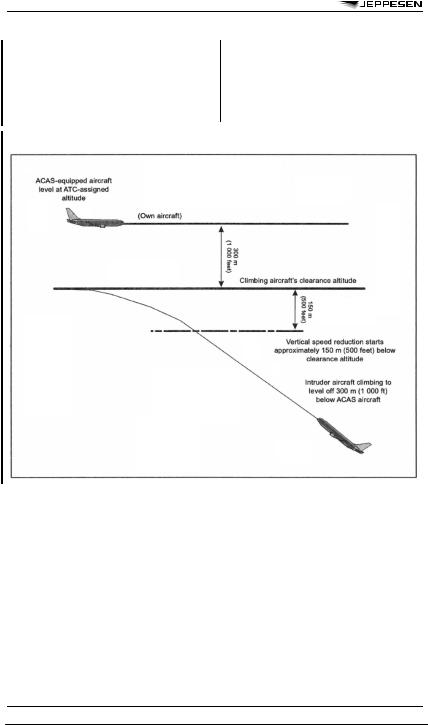
3.3HIGH VERTICAL RATE (HVR) ENCOUNTERS
Pilots should use appropriate procedures by which an aeroplane climbing or descending to an assigned altitude or flight level, especially with an autopilot engaged, may do so at a rate less than 8 m/s (or 1500 ft/min) throughout the last 300 m (or 1000 ft) of climb or descent to the assigned altitude or flight
level when the pilot is made aware of another aircraft at or approaching an adjacent altitude or flight level, unless otherwise instructed by ATC. These procedures are intended to avoid unnecessary ACAS II resolution advisories in aircraft at or approaching adjacent altitudes or flight levels. For commercial operations, these procedures should be specified by the operator.
Figure III-3-3-B-1. Representative HVR encounter geometry
© JEPPESEN, 2002, 2009. ALL RIGHTS RESERVED.

5 JUN 09 |
AIR TRAFFIC CONTROL |
287 |
AIRCRAFT OPERATING PROCEDURES - OPERATIONAL FLIGHT INFORMATION
1AERODROME SURFACE
OPERATIONS
1.1 Operators shall develop and implement standard operating procedures (SOPs) for aerodrome surface operations. The development and implementation of SOPs shall take into consideration the risk factors (listed in 1.3) associated with the following operations:
a.runway intersection take-offs;
b.line-up and wait clearances;
c.land and hold-short clearances;
d.take-offs from displaced runway thresholds;
e.hazards associated with runway crossing traffic;
f.hazards associated with runway crossing traffic in the case of closely spaced parallel runways; and
g.hazards associated with the risk of collision at hot spot locations on aerodromes.
1.3Operators should ensure that flight personnel are aware of the risk factors in the aerodrome surface operations listed in 1.1. Such risk factors should include, but not be limited to:
a.human error due to excessive workload, loss of vigilance and fatigue;
b.potential distractions associated with the performance of flight deck tasks; and
c.failure to use standard phraseology in aeronautical communications.
2READ-BACK OF CLEARANCES AND SAFETY-RELATED
INFORMATION
NOTE: Provisions on read-back of clearances and safety-related information are included in Annex 11, Chapter 3, 3.7.3, and in the PANS-ATM (Doc 4444), Chapter 4.
3STABILIZED APPROACH PROCEDURE
3.1GENERAL
The primary safety consideration in the development of the stabilized approach procedure shall be maintenance of the intended flight path as depicted in the published approach procedure, without excessive manoeuvring. The parameters to be considered in the definition of a stabilized approach are listed in 3.2.
3.2PARAMETERS FOR THE STABILIZED APPROACH
The parameters for the stabilized approach shall be defined by the operator’s standard operating procedures (SOPs) (Section 5, Chapter 1). These parameters shall be included in the operator’s operations manual and shall provide details regarding at least the following:
a.range of speeds specific to each aircraft type;
b.minimum power setting(s) specific to each aircraft type;
c.range of attitudes specific to each aircraft type;
d.crossing altitude deviation tolerances;
e.configuration(s) specific to each aircraft type;
f.maximum sink rate; and
g.completion of checklists and crew briefings.
3.3ELEMENTS OF THE STABILIZED APPROACH
The elements of a stabilized approach (according to the parameters in 3.2) shall be stated in the operator’s SOPs. These elements should include as a minimum:
a.that in instrument meteorological conditions (IMC), all flights shall be stabilized by no lower than 300 m (1000 ft) height above threshold; and
b.that all flights of any nature shall be stabilized by no lower than 150 m (500 ft) height above threshold.
3.4GO-AROUND POLICY
Standard operating procedures should include the operator’s policy with regard to the parameters in 3.2 and the elements in 3.3. This policy should state that if an approach is not stabilized in accordance with 3.3, or has become destabilized at any subsequent point during an approach, a go-around is required. Operators should reinforce this policy through training.
© JEPPESEN, 2002, 2009. ALL RIGHTS RESERVED.