

Курсовая работа по РЗА / Терминалы / каталоги / 7SJ62xx_Catalog_SIP-2008_en
.pdfCommunication
In terms of communication, the units offer substantial flexibility in the context of connection to industrial and power automation standards. Communication can be extended or added on thanks to modules for retrofitting on which the common protocols run. Therefore, also in the future it will be possible to optimally integrate units into the changing communication infrastructure, for example in Ethernet networks (which will also be used increasingly in the power supply sector in the years to come).
Serial front interface
There is a serial RS232 interface on the front of all the units. All of the unit’s functions can be set on a PC by means of the DIGSI 4 protection operation program. Commissioning tools and fault analysis are also built into the program and are available through this interface.
Rear-mounted interfaces1)
A number of communication modules suitable for various applications can be fitted in the rear of the flush-mounting housing. In the flush-mounting housing, the modules can be easily replaced by the user. The interface modules support the following applications:
•Time synchronization interface
All units feature a permanently integrated electrical time synchronization interface. It can be used to feed timing telegrams in IRIG-B or DCF77 format into the units via time synchronization receivers.
•System interface
Communication with a central control system takes place through this interface. Radial or ring type station bus topologies can be configured depending on the chosen interface. Furthermore, the units can exchange data through this interface via Ethernet and IEC 61850 protocol and can also be operated by DIGSI.
•Service interface
The service interface was conceived for remote access to a number of protection units via DIGSI. On all units, it can be an electrical RS232/RS485 or an optical interface. For special applications, a maximum of two temperature monitoring boxes (RTD-box) can be connected to this interface as an alternative.
1)For units in panel surface-mounting housings please refer to note on page 5/136.
System interface protocols (retrofittable)
IEC 61850 protocol
Since 2004, the Ethernet-based IEC 61850 protocol is the worldwide standard for protection and control systems used by power supply corporations. Siemens was the first manufacturer to support this standard. By means of this protocol, information can also be exchanged directly between bay units so as to set up simple masterless systems for bay and system interlocking. Access to the units via the Ethernet bus is also possible with DIGSI.
IEC 60870-5-103 protocol
The IEC 60870-5-103 protocol is an international standard for the transmission of protective data and fault recordings. All messages from the unit and also control commands can be transferred by means of published, Siemens-specific extensions to the protocol.
Redundant solutions are also possible. Optionally it is possible to read out and alter individual parameters (only possible with the redundant module).
PROFIBUS-DP protocol
PROFIBUS-DP is the most widespread protocol in industrial automation. Via PROFIBUS-DP, SIPROTEC units make their information available to a SIMATIC controller or, in the control direction, receive commands from a central SIMATIC. Measured values can also be transferred.
MODBUS RTU protocol
This uncomplicated, serial protocol is mainly used in industry and by power supply corporations, and is supported by a number of unit manufacturers. SIPROTEC units function as MODBUS slaves, making their information available to a master or receiving information from it. A timestamped event list is available.
5 Overcurrent Protection / 7SJ62
Fig. 5/109
IEC 60870-5-103: Radial fiber-optic connection
5
Fig. 5/110
Bus structure for station bus with Ethernet and IEC 61850, fiber-optic ring
Siemens SIP · 2008 |
5/115 |

5 Overcurrent Protection / 7SJ62
Communication
DNP 3.0 protocol
Power supply corporations use the serial DNP 3.0 (Distributed Network Protocol) for the station and network control levels. SIPROTEC units function as DNP slaves, supplying their information to a master system or receiving information from it.
System solutions for protection and station control
Together with the SICAM power automation system, SIPROTEC 4 can be used with PROFIBUS-FMS. Over the low-cost electrical RS485 bus, or interference-free via the optical double ring, the units exchange
information with the control system.
5
Units featuring IEC 60870-5-103 interfaces can be connected to SICAM in parallel via the RS485 bus or radially by fiber-optic link. Through this interface, the system is open for the connection of units of other manufacturers (see Fig. 5/109).
Because of the standardized interfaces, SIPROTEC units can also be integrated into systems of other manufacturers or in SIMATIC. Electrical RS485 or optical interfaces are available. The optimum physical data transfer medium can be chosen thanks to opto-electrical converters. Thus, the RS485 bus allows low-cost wiring in the cubicles and an interference-free optical connection to the master can be established.
For IEC 61850, an interoperable system solution is offered with SICAM PAS. Via the 100 Mbits/s Ethernet bus, the units are linked with PAS electrically or optically to the station PC. The interface is standardized, thus also enabling direct connection of units of other manufacturers to the Ethernet bus. With IEC 61850, however, the units can also be used in other manufacturers’ systems (see Fig. 5/110).
Fig. 5/111
System solution/communication
Fig. 5/112
Optical Ethernet communication module
for IEC 61850 with integrated Ethernet-switch
LSP2810.tif
5/116 |
Siemens SIP · 2008 |
5 Overcurrent Protection / 7SJ62
Typical connections
Connection of current and voltage transformers
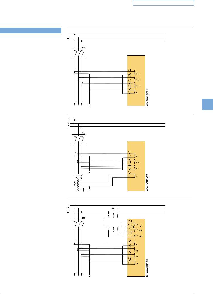
Standard connection
For earthed networks, the earth current is obtained from the phase currents by the residual current circuit.
Fig. 5/113
Residual current circuit without direc-
tional element
5
Fig. 5/114
Sensitive earthcurrent detection without directional element
Fig. 5/115
Residual current circuit with directional element
Siemens SIP · 2008 |
5/117 |

5 Overcurrent Protection / 7SJ62
Typical connections
Connection for compensated networks
The figure shows the connection of two phase-to-earth voltages and the VE voltage of the open delta winding and a phasebalance neutral current transformer for the earth current. This connection maintains maximum precision for directional earthfault detection and must be used in compensated networks.
Fig. 5/116 shows sensitive directional earth-fault detection.
5
Connection for isolated-neutral or compensated networks only
If directional earth-fault protection is not used, the connection can be made with only two phase current transformers. Directional phase short-circuit protection can be achieved by using only two primary transformers.
Connection for the synchro-check function
The 3-phase system is connected as reference voltage, i. e. the outgoing voltages as well as a single-phase voltage, in this case a busbar voltage, that has to be ckecked for synchronism.
Fig. 5/116
Sensitive directional earth-fault detection with directional element for phases
Fig. 5/117
Isolated-neutral or compensated networks
Fig. 5/118
Measuring of the busbar voltage and the outgoing feeder voltage for the synchro-check
5/118 |
Siemens SIP · 2008 |

5 Overcurrent Protection / 7SJ62
Typical applications
Overview of connection types
Type of network |
Function |
|
|
|
|
|
|
|
|
|
Current connection |
Voltage connection |
|||||||||||||||||||||||
(Low-resistance) earthed network |
Time-overcurrent protection |
Residual circuit, with 3 phase-current |
- |
|
|
|
|
|
|
|
|
|
|
|
|
|
|
|
|
||||||||||||||||
|
phase/earth non-directional |
transformers required, phase-balance |
|
|
|
|
|
|
|
|
|
|
|
|
|
|
|
|
|
||||||||||||||||
|
|
|
|
|
|
|
|
|
|
|
neutral current transformer possible |
|
|
|
|
|
|
|
|
|
|
|
|
|
|
|
|
|
|||||||
|
|
|
|
|
|
|
|
|
|
|
|
|
|
|
|
|
|
|
|
|
|
|
|
|
|
|
|
|
|
|
|
|
|
|
|
(Low-resistance) earthed networks |
Sensitive earth-fault protection |
Phase-balance neutral current |
- |
|
|
|
|
|
|
|
|
|
|
|
|
|
|
|
|
||||||||||||||||
|
|
|
|
|
|
|
|
|
|
|
transformers required |
|
|
|
|
|
|
|
|
|
|
|
|
|
|
|
|
|
|||||||
|
|
|
|
|
|
|
|
|
|
|
|
|
|
|
|
|
|
|
|
|
|
|
|
|
|
|
|
|
|
|
|
|
|
|
|
Isolated or compensated networks |
Time-overcurrent protection |
Residual circuit, with 3 or 2 phase |
- |
|
|
|
|
|
|
|
|
|
|
|
|
|
|
|
|
||||||||||||||||
|
phases non-directional |
current transformers possible |
|
|
|
|
|
|
|
|
|
|
|
|
|
|
|
|
|
||||||||||||||||
|
|
|
|
|
|
|
|
|
|
|
|
|
|
|
|
|
|
|
|
|
|
|
|
|
|
|
|
|
|
|
|
|
|
||
(Low-resistance) earthed networks |
Time-overcurrent protection |
Residual circuit, with 3 phase-current |
Phase-to-earth connection or |
||||||||||||||||||||||||||||||||
|
phases directional |
transformers possible |
phase-to-phase connection |
||||||||||||||||||||||||||||||||
|
|
|
|
|
|
|
|
|
|
|
|
|
|
|
|
|
|
|
|
|
|
|
|
|
|
|
|
|
|
|
|
|
|
||
Isolated or compensated networks |
Time-overcurrent protection |
Residual circuit, with 3 or 2 phase- |
Phase-to-earth connection or |
||||||||||||||||||||||||||||||||
|
phases directional |
current transformers possible |
phase-to-phase connection |
||||||||||||||||||||||||||||||||
|
|
|
|
|
|
|
|
|
|
|
|
|
|
|
|
|
|
|
|
|
|
|
|
|
|
|
|
|
|
|
|
|
|
|
|
(Low-resistance) earthed networks |
Time-overcurrent protection |
Residual circuit, with 3 phase-current |
Phase-to-earth connection required |
|
|||||||||||||||||||||||||||||||
|
|||||||||||||||||||||||||||||||||||
|
earth directional |
transformers required, phase-balance |
|
|
|
|
|
|
|
|
|
|
|
|
|
|
|
|
5 |
||||||||||||||||
|
|
|
|
|
|
|
|
|
|
|
neutral current transformers possible |
|
|
|
|
|
|
|
|
|
|
|
|
|
|
|
|
||||||||
|
|
|
|
|
|
|
|
|
|
|
|
|
|
|
|
|
|
|
|
|
|
|
|
|
|
|
|
|
|
|
|
|
|
|
|
|
|
|
|
|
|
|
|
|
|
|
|
|
|
|
|
|
|
|
|
|
|
|
|
|
|
|
|
|
|
|
|
|
|
|
|
Isolated networks |
Sensitive earth-fault |
Residual circuit, if earth current |
3 times phase-to-earth connection or |
||||||||||||||||||||||||||||||||
|
protection |
|
|
|
|
|
|
|
|
|
> 0.05 IN on secondary side, other- |
phase-to-earth connection with open |
|||||||||||||||||||||||
|
|
|
|
|
|
|
|
|
|
|
wise phase-balance neutral current |
delta winding |
|||||||||||||||||||||||
|
|
|
|
|
|
|
|
|
|
|
transformers required |
|
|
|
|
|
|
|
|
|
|
|
|
|
|
|
|
|
|||||||
|
|
|
|
|
|
|
|
|
|
|
|
|
|
|
|
|
|
|
|
|
|
|
|
|
|
|
|
|
|
|
|
|
|
||
Compensated networks |
Sensitive earth-fault protection |
Phase-balance neutral current |
Phase-to-earth connection with open |
||||||||||||||||||||||||||||||||
|
cos ϕ measurement |
transformers required |
delta winding required |
||||||||||||||||||||||||||||||||
Connection of circuit-breaker |
|
|
|
|
|
|
|
|
|
|
|
|
|
|
|
|
|
|
|
|
|
|
|
|
|
|
|
|
|
|
|
|
|
|
|
Undervoltage releases |
|
|
|
|
|
|
|
|
|
|
|
|
|
|
|
|
|
|
|
|
|
|
|
|
|
|
|
|
|
|
|
|
|
|
|
|
|
|
|
|
|
|
|
|
|
|
|
|
|
|
|
|
|
|
|
|
|
|
|
|
|
|
|
|
|
|
|
|
|
|
|
|
|
|
|
|
|
|
|
|
|
|
|
|
|
|
|
|
|
|
|
|
|
|
|
|
|
|
|
|
|
|
|
|
|
|
|
Undervoltage releases are used for auto- |
|
|
|
|
|
|
|
|
|
|
|
|
|
|
|
|
|
|
|
|
|
|
|
|
|
|
|
|
|
|
|
|
|
|
|
matic tripping of high-voltage motors. |
|
|
|
|
|
|
|
|
|
|
|
|
|
|
|
|
|
|
|
|
|
|
|
|
|
|
|
|
|
|
|
|
|
|
|
Example: |
|
|
|
|
|
|
|
|
|
|
|
|
|
|
|
|
|
|
|
|
|
|
|
|
|
|
|
|
|
|
|
|
|
|
|
|
|
|
|
|
|
|
|
|
|
|
|
|
|
|
|
|
|
|
|
|
|
|
|
|
|
|
|
|
|
|
|
|
|
|
|
|
|
|
|
|
|
|
|
|
|
|
|
|
|
|
|
|
|
|
|
|
|
|
|
|
|
|
|
|
|
|
|
|
|
|
|
|
|
|
|
|
|
|
|
|
|
|
|
|
|
|
|
|
|
|
|
|
|
|
|
|
|
|
|
|
|
|
|
|
|
|
|
DC supply voltage of control system fails |
|
|
|
|
|
|
|
|
|
|
|
|
|
|
|
|
|
|
|
|
|
|
|
|
|
|
|
|
|
|
|
|
|
|
|
|
|
|
|
|
|
|
|
|
|
|
|
|
|
|
|
|
|
|
|
|
|
|
|
|
|
|
|
|
|
|
|
|
|
||
and manual electric tripping is no longer |
|
|
|
|
|
|
|
|
|
|
|
|
|
|
|
|
|
|
|
|
|
|
|
|
|
|
|
|
|
|
|
|
|
|
|
|
|
|
|
|
|
|
|
|
|
|
|
|
|
|
|
|
|
|
|
|
|
|
|
|
|
|
|
|
|
|
|
|
|
||
|
|
|
|
|
|
|
|
|
|
|
|
|
|
|
|
|
|
|
|
|
|
|
|
|
|
|
|
|
|
|
|
|
|
||
possible. |
|
|
|
|
|
|
|
|
|
|
|
|
|
|
|
|
|
|
|
|
|
|
|
|
|
|
|
|
|
|
|
|
|
|
|
|
|
|
|
|
|
|
|
|
|
|
|
|
|
|
|
|
|
|
|
|
|
|
|
|
|
|
|
|
|
|
|
|
|
|
|
Automatic tripping takes place when volt- |
|
|
|
|
|
|
|
|
|
|
|
|
|
|
|
|
|
|
|
|
|
|
|
|
|
|
|
|
|
|
|
|
|
|
|
|
|
|
|
|
|
|
|
|
|
|
|
|
|
|
|
|
|
|
|
|
|
|
|
|
|
|
|
|
|
|
|
|
|
||
|
|
|
|
|
|
|
|
|
|
|
|
|
|
|
|
|
|
|
|
|
|
|
|
|
|
|
|
|
|
|
|
|
|
||
age across the coil drops below the trip |
|
|
|
|
|
|
|
|
|
|
|
|
|
|
|
|
|
|
|
|
|
|
|
|
|
|
|
|
|
|
|
|
|
|
|
|
|
|
|
|
|
|
|
|
|
|
|
|
|
|
|
|
|
|
|
|
|
|
|
|
|
|
|
|
|
|
|
|
|
||
limit. In Fig. 5/119, tripping occurs due to |
|
|
|
|
|
|
|
|
|
|
|
|
|
|
|
|
|
|
|
|
|
|
|
|
|
|
|
|
|
|
|
|
|
|
|
|
|
|
|
|
|
|
|
|
|
|
|
|
|
|
|
|
|
|
|
|
|
|
|
|
|
|
|
|
|
|
|
|
|
||
failure of DC supply voltage, by automatic |
|
|
|
|
|
|
|
|
|
|
|
|
|
|
|
|
|
|
|
|
|
|
|
|
|
|
|
|
|
|
|
|
|
|
|
opening of the live status contact upon |
Fig. 5/119 Undervoltage release with make contact (50, 51) |
|
|
|
|
|
|
|
|
|
|
|
|
|
|
|
|
|
|||||||||||||||||
failure of the protection unit or by |
|
|
|
|
|
|
|
|
|
|
|
|
|
|
|
|
|
|
|
|
|
|
|
|
|
|
|
|
|
|
|
|
|
|
|
short-circuiting the trip coil in event of |
|
|
|
|
|
|
|
|
|
|
|
|
|
|
|
|
|
|
|
|
|
|
|
|
|
|
|
|
|
|
|
|
|
|
|
network fault. |
|
|
|
|
|
|
|
|
|
|
|
|
|
|
|
|
|
|
|
|
|
|
|
|
|
|
|
|
|
|
|
|
|
|
|
In Fig. 5/120 tripping is by failure of auxil- |
|
|
|
|
|
|
|
|
|
|
|
|
|
|
|
|
|
|
|
|
|
|
|
|
|
|
|
|
|
|
|
|
|
|
|
|
|
|
|
|
|
|
|
|
|
|
|
|
|
|
|
|
|
|
|
|
|
|
|
|
|
|
|
|
|
|
|
|
|
||
iary voltage and by interruption of tripping |
|
|
|
|
|
|
|
|
|
|
|
|
|
|
|
|
|
|
|
|
|
|
|
|
|
|
|
|
|
|
|
|
|
|
|
|
|
|
|
|
|
|
|
|
|
|
|
|
|
|
|
|
|
|
|
|
|
|
|
|
|
|
|
|
|
|
|
|
|
||
circuit in the event of network failure. |
|
|
|
|
|
|
|
|
|
|
|
|
|
|
|
|
|
|
|
|
|
|
|
|
|
|
|
|
|
|
|
|
|
|
|
Upon failure of the protection unit, the |
|
|
|
|
|
|
|
|
|
|
|
|
|
|
|
|
|
|
|
|
|
|
|
|
|
|
|
|
|
|
|
|
|
|
|
|
|
|
|
|
|
|
|
|
|
|
|
|
|
|
|
|
|
|
|
|
|
|
|
|
|
|
|
|
|
|
|
|
|
||
tripping circuit is also interrupted, since |
|
|
|
|
|
|
|
|
|
|
|
|
|
|
|
|
|
|
|
|
|
|
|
|
|
|
|
|
|
|
|
|
|
|
|
|
|
|
|
|
|
|
|
|
|
|
|
|
|
|
|
|
|
|
|
|
|
|
|
|
|
|
|
|
|
|
|
|
|
||
|
|
|
|
|
|
|
|
|
|
|
|
|
|
|
|
|
|
|
|
|
|
|
|
|
|
|
|
|
|
|
|
|
|
||
contact held by internal logic drops back |
|
|
|
|
|
|
|
|
|
|
|
|
|
|
|
|
|
|
|
|
|
|
|
|
|
|
|
|
|
|
|
|
|
|
|
|
|
|
|
|
|
|
|
|
|
|
|
|
|
|
|
|
|
|
|
|
|
|
|
|
|
|
|
|
|
|
|
|
|
||
into open position. |
|
|
|
|
|
|
|
|
|
|
|
|
|
|
|
|
|
|
|
|
|
|
|
|
|
|
|
|
|
|
|
|
|
|
|
|
|
|
|
|
|
|
|
|
|
|
|
|
|
|
|
|
|
|
|
|
|
|
|
|
|
|
|
|
|
|
|
|
|
|
|
|
|
|
|
|
|
|
|
|
|
|
|
|
|
|
|
|
|
|
|
|
|
|
|
|
|
|
|
|
|
|
|
|
|
|
|
|
|
|
|
|
|
|
|
|
|
|
|
|
|
|
|
|
|
|
|
|
|
|
|
|
|
|
|
|
|
|
|
|
|
|
|
|
|
|
|
|
|
|
|
|
|
|
|
|
|
|
|
|
|
|
|
|
|
|
|
|
|
|
|
|
|
|
|
|
|
|
|
|
|
|
|
|
|
|
|
|
|
|
|
|
|
|
|
|
|
|
|
|
|
|
|
|
|
|
|
|
|
|
|
|
|
|
|
Fig. 5/120 Undervoltage trip with locking contact (trip signal 50 is inverted)
Siemens SIP · 2008 |
5/119 |

5 Overcurrent Protection / 7SJ62
Typical applications
Trip circuit supervision (ANSI 74TC)
One or two binary inputs can be used for monitoring the circuit-breaker trip coil including its incoming cables. An alarm signal occurs whenever the circuit is interrupted.
Lockout (ANSI 86)
All binary outputs can be stored like LEDs and reset using the LED reset key. The lockout state is also stored in the event of supply voltage failure. Reclosure can only occur after the lockout state is reset.
5
Reverse-power protection for dual supply (ANSI 32R)
If power is fed to a busbar through two parallel infeeds, then in the event of any fault on one of the infeeds it should be selectively interrupted. This ensures a continued supply to the busbar through the remaining infeed. For this purpose, directional devices are needed which detect a short-circuit current or a power flow from the busbar in the direction of the infeed. The directional time-overcurrent protection is usually set via the load current. It cannot be used to deactivate low-current faults. Reverse-power protection can be set far below the rated power. This ensures that it also detects power feedback into the line in the event of low-current faults with levels far below the load current. Reverse-power protection is performed via the “flexible protection functions” of the 7SJ62.
Fig. 5/121 Trip circuit supervision with 2 binary inputs
Fig. 5/122 Reverse-power protection for dual supply
5/120 |
Siemens SIP · 2008 |

Technical data |
|
|
|
|
|
|
|
|
|
|
|
|
|
|
|
|
|
General unit data |
|
|
|
|
|
|
|
|
Measuring circuits |
|
|
|
|
|
|
|
|
System frequency |
|
|
|
|
50 / 60 Hz (settable) |
|||
Current transformer |
|
|
|
|
|
|
|
|
Rated current Inom |
|
|
|
|
1 or 5 A (settable) |
|||
Option: sensitive earth-fault CT |
|
|
IEE < 1.6 A |
|
||||
Power consumption |
|
|
|
|
|
|
|
|
at Inom = 1 A |
|
|
|
|
Approx. 0.05 VA per phase |
|||
at Inom = 5 A |
|
|
|
|
Approx. 0.3 VA per phase |
|||
for sensitive earth-fault CT at 1 A |
Approx. 0.05 VA |
|||||||
Overload capability |
|
|
|
|
|
|
|
|
Thermal (effective) |
|
|
|
|
100 x Inom for 1 s |
|||
|
|
|
|
|
30 x Inom for 10 s |
|||
|
|
|
|
|
4 x Inom continuous |
|||
Dynamic (impulse current) |
|
|
250 x Inom (half cycle) |
|||||
Overload capability if equipped with |
|
|
|
|
||||
sensitive earth-fault CT |
|
|
|
|
|
|
|
|
Thermal (effective) |
|
|
|
|
300 A for 1 s |
|
||
|
|
|
|
|
100 A for 10 s |
|
||
|
|
|
|
|
15 A continuous |
|||
Dynamic (impulse current) |
|
|
750 A (half cycle) |
|||||
Voltage transformer |
|
|
|
|
|
|
|
|
Type |
|
|
|
|
7SJ621 |
7SJ623 |
||
|
|
|
|
|
7SJ622 |
7SJ622 |
||
Number |
|
|
|
|
3 |
|
|
4 |
Rated voltage Vnom |
|
|
|
|
100 V to 225 V |
|||
Measuring range |
|
|
|
|
0 V to 170 V |
|
||
Power consumption at Vnom = 100 V |
< 0.3 VA per phase |
|||||||
Overload capability in voltage path |
|
|
|
|
||||
(phase-neutral voltage) |
|
|
|
|
|
|
|
|
Thermal (effective) |
|
|
|
|
230 V continuous |
|||
Auxiliary voltage |
|
|
|
|
|
|
|
|
Rated auxiliary |
DC |
24/48 V |
60/125 V |
110/250 V |
||||
voltage Vaux |
AC |
|
|
|
|
|
115/230 V |
|
Permissible tolerance |
DC |
19–58 V |
48–150 V 88–300 V |
|||||
|
AC |
|
|
|
|
|
92-138 V 184–265 V |
|
Ripple voltage, |
≤ 12 % |
|
|
|
|
|||
peak-to-peak |
|
|
|
|
|
|
|
|
Power consumption |
|
|
|
|
|
|
|
|
Quiescent |
Approx. 4 W |
|
|
|
||||
Energized |
Approx. 7 W |
|
|
|
||||
Backup time during |
≥ 50 ms at V ≥ 110 V DC |
|||||||
loss/short circuit of |
≥ 20 ms at V ≥ 24 V DC |
|||||||
auxiliary voltage |
≥ 200 ms at 115 V/230 V AC |
|||||||
Binary inputs/indication inputs |
|
|
|
|
|
|
||
Type |
|
7SJ621 |
|
|
|
7SJ622 |
||
|
|
7SJ623 |
|
|
|
7SJ624 |
||
Number |
8 |
|
|
|
|
|
11 |
|
Voltage range |
|
24–250 V DC |
|
|
|
|||
Pickup threshold modifiable by plug-in jumpers |
|
|||||||
Pickup threshold |
|
19 V DC |
|
|
|
88 V DC |
||
For rated control voltage |
24/48/60/ |
|
|
|
110/125/ |
|||
|
|
110/125 V |
|
|
220/250 V DC |
|||
Response time/drop-out |
|
Approx. 3.5 |
|
|
|
|||
time |
|
|
|
|
|
|
|
|
Power consumption |
|
1.8 mA (independent of operating voltage) |
||||||
energized |
|
|
|
|
|
|
|
|
5 Overcurrent Protection / 7SJ62
Binary outputs/command outputs
Type |
7SJ621 |
7SJ622 |
|
|
|
7SJ623 |
7SJ624 |
|
|
Command/indication relay |
8 |
6 |
|
|
Contacts per command/ |
1 NO / form A |
|
||
indication relay |
(Two contacts changeable to NC/form |
|
||
|
B, via jumpers) |
|
||
Live status contact |
1 NO / NC (jumper) / form A/B |
|
||
Switching capacity |
|
|
|
|
Make |
1000 W / VA |
|
||
Break |
30 W / VA / 40 W resistive / |
|
||
|
25 W at L/R ≤ 50 ms |
|
||
Switching voltage |
≤ 250 V DC |
|
||
Permissible current |
5 A continuous, |
|
||
|
30 A for 0.5 s making current, |
|
|
|
|
|
|||
|
2000 switching cycles |
|
5 |
|
|
|
|
|
|
|
|
|
|
|
Electrical tests |
|
|
|
|
Specification |
|
|
|
|
Standards |
IEC 60255 |
|
|
|
|
ANSI C37.90, C37.90.1, C37.90.2, |
|
||
|
UL508 |
|
|
|
Insulation tests |
|
|
|
|
Standards |
IEC 60255-5; ANSI/IEEE C37.90.0 |
|
||
Voltage test (100 % test) |
2.5 kV (r.m.s. value), 50/60 Hz |
|
||
all circuits except for auxiliary |
|
|
|
|
voltage and RS485/RS232 and |
|
|
|
|
time synchronization |
|
|
|
|
Auxiliary voltage |
3.5 kV DC |
|
|
|
|
|
|
|
|
Communication ports |
500 V AC |
|
|
|
and time synchronization |
|
|
|
|
Impulse voltage test (type test) |
5 kV (peak value); 1.2/50 µs; 0.5 J |
|
||
all circuits, except communication |
3 positive and 3 negative impulses |
|
||
ports and time synchronization, |
at intervals of 5 s |
|
||
class III |
|
|
|
|
EMC tests for interference immunity; type tests |
|
|
|
|
Standards |
IEC 60255-6; IEC 60255-22 |
|
||
|
(product standard) |
|
||
|
EN 50082-2 (generic specification) |
|
||
|
DIN 57435 Part 303 |
|
||
High-frequency test |
2.5 kV (peak value); 1 MHz; τ =15 ms; |
|
||
IEC 60255-22-1, class III |
400 surges per s; test duration 2 s |
|
||
and VDE 0435 Part 303, class III |
|
|
|
|
Electrostatic discharge |
8 kV contact discharge; |
|
||
IEC 60255-22-2 class IV |
15 kV air gap discharge; |
|
||
and EN 61000-4-2, class IV |
both polarities; 150 pF; Ri = 330 Ω |
|
||
Irradiation with radio-frequency |
10 V/m; 27 to 500 MHz |
|
||
field, non-modulated |
|
|
|
|
IEC 60255-22-3 (Report) class III |
|
|
|
|
Irradiation with radio-frequency |
10 V/m, 80 to 1000 MHz; |
|
||
field, amplitude-modulated |
AM 80 %; 1 kHz |
|
||
IEC 61000-4-3; class III |
|
|
|
|
Irradiation with radio-frequency |
10 V/m, 900 MHz; repetition |
|
||
field, pulse-modulated |
rate 200 Hz, on duration 50 % |
|
||
IEC 61000-4-3/ENV 50204; class III |
|
|
|
|
Fast transient interference/burst |
4 kV; 5/50 ns; 5 kHz; |
|
||
IEC 60255-22-4 and IEC 61000-4-4, |
burst length = 15 ms; |
|
||
class IV |
repetition rate 300 ms; both polarities; |
|
||
|
Ri = 50 Ω; test duration 1 min |
|
||
|
|
|
|
|
Siemens SIP · 2008 |
5/121 |

5 Overcurrent Protection / 7SJ62
Technical data
|
|
EMC tests for interference immunity; type tests (cont'd) |
|
|
|
High-energy surge voltages |
|
|
|
(Surge) |
|
|
|
IEC 61000-4-5; class III |
|
|
|
Auxiliary voltage |
From circuit to circuit: 2 kV; 12 Ω; 9 µF |
|
|
|
across contacts: 1 kV; 2 Ω ;18 µF |
|
|
Binary inputs/outputs |
From circuit to circuit: 2 kV; 42 Ω; 0.5 µF |
|
|
|
across contacts: 1 kV; 42 Ω; 0.5 µF |
|
|
Line-conducted HF, |
10 V; 150 kHz to 80 MHz; |
|
|
amplitude-modulated |
AM 80 %; 1 kHz |
|
|
IEC 61000-4-6, class III |
|
|
|
Power frequency magnetic field |
30 A/m; 50 Hz, continuous |
|
|
IEC 61000-4-8, class IV |
300 A/m; 50 Hz, 3 s |
|
|
IEC 60255-6 |
0.5 mT, 50 Hz |
|
|
Oscillatory surge withstand |
2.5 to 3 kV (peak value), 1 to 1.5 MHz |
|
|
capability |
damped wave; 50 surges per s; |
|
|||
5 |
|
ANSI/IEEE C37.90.1 |
duration 2 s, Ri = 150 to 200 Ω |
|
Fast transient surge withstand |
4 to 5 kV; 10/150 ns; 50 surges per s |
|
|
|
capability ANSI/IEEE C37.90.1 |
both polarities; duration 2 s, Ri = 80 Ω |
|
|
Radiated electromagnetic |
35 V/m; 25 to 1000 MHz; |
|
|
interference |
amplitude and pulse-modulated |
|
|
ANSI/IEEE C37.90.2 |
|
|
|
Damped wave |
2.5 kV (peak value, polarity |
|
|
IEC 60694 / IEC 61000-4-12 |
alternating) |
|
|
|
100 kHz, 1 MHz, 10 and 50 MHz, |
|
|
|
Ri = 200 Ω |
|
|
EMC tests for interference emission; type tests |
|
|
|
Standard |
EN 50081-* (generic specification) |
|
|
Conducted interferences |
150 kHz to 30 MHz |
|
|
only auxiliary voltage IEC/CISPR 22 |
Limit class B |
|
|
Radio interference field strength |
30 to 1000 MHz |
|
|
IEC/CISPR 11 |
Limit class B |
|
|
Units with a detached operator |
|
|
|
panel must be installed in a metal |
|
|
|
cubicle to maintain limit class B |
|
|
|
|
|
Mechanical stress tests
Vibration, shock stress and seismic vibration
During operation |
|
||
|
|
|
|
Standards |
IEC 60255-21 and IEC 60068-2 |
||
|
|
|
|
Vibration |
Sinusoidal |
||
IEC 60255-21-1, class 2 |
10 to 60 Hz; +/- 0.075 mm amplitude; |
||
IEC 60068-2-6 |
60 to 150 Hz; 1 g acceleration |
||
|
|
|
frequency sweep 1 octave/min |
|
|
|
20 cycles in 3 perpendicular axes |
Shock |
Semi-sinusoidal |
||
IEC 60255-21-2, class 1 |
Acceleration 5 g, duration 11 ms; |
||
IEC 60068-2-27 |
3 shocks in both directions of 3 axes |
||
Seismic vibration |
Sinusoidal |
||
IEC 60255-21-3, class 1 |
1 to 8 Hz: ± 3.5 mm amplitude |
||
IEC 60068-3-3 |
(horizontal axis) |
||
|
|
|
1 to 8 Hz: ± 1.5 mm amplitude |
|
|
|
(vertical axis) |
|
|
|
8 to 35 Hz: 1 g acceleration |
|
|
|
(horizontal axis) |
|
|
|
8 to 35 Hz: 0.5 g acceleration |
|
|
|
(vertical axis) |
|
|
|
Frequency sweep 1 octave/min |
|
|
|
1 cycle in 3 perpendicular axes |
|
|
|
|
During transportation |
|
||
|
|
|
|
Standards |
IEC 60255-21 and IEC 60068-2 |
||
|
|
||
Vibration |
Sinusoidal |
||
IEC 60255-21-1, class 2 |
5 to 8 Hz: ± 7.5 mm amplitude; |
||
IEC 60068-2-6 |
8 to 150 Hz; 2 g acceleration, |
||
|
|
|
frequency sweep 1 octave/min |
|
|
|
20 cycles in 3 perpendicular axes |
Shock |
Semi-sinusoidal |
||
IEC 60255-21-2, Class 1 |
Acceleration 15 g, duration 11 ms |
||
IEC 60068-2-27 |
3 shocks in both directions of 3 axes |
||
Continuous shock |
Semi-sinusoidal |
||
IEC 60255-21-2, class 1 |
Acceleration 10 g, duration 16 ms |
||
IEC 60068-2-29 |
1000 shocks in both directions |
||
|
|
|
of 3 axes |
|
|
||
Climatic stress tests |
|
||
Temperatures |
|
||
Type-tested acc. to IEC 60068-2-1 |
-25 °C to +85 °C /-13 °F to +185 °F |
||
and -2, test Bd, for 16 h |
|
||
Temporarily permissible operating |
-20 °C to +70 °C /-4 °F to -158 °F |
||
temperature, tested for 96 h |
|
||
Recommended permanent operat- |
-5 °C to +55 °C /+25 °F to +131 °F |
||
ing temperature acc. to IEC 60255-6 |
|
||
(Legibility of display may be |
|
||
impaired above +55 °C /+131 °F) |
|
||
– Limiting temperature during |
-25 °C to +55 °C /-13 °F to +131 °F |
||
permanent storage |
|
||
– Limiting temperature during |
-25 °C to +70 °C /-13 °F to +158 °F |
||
transport |
|
||
Humidity |
|
||
Permissible humidity |
Annual average 75 % relative humid- |
||
It is recommended to arrange the |
ity; on 56 days a year up to 95 % rela- |
||
units in such a way that they are not |
tive humidity; condensation not |
||
exposed to direct sunlight or |
permissible! |
||
pronounced temperature changes |
|
||
that could cause condensation. |
|
||
Unit design |
|
||
|
|
|
|
Housing
Dimensions
Weight
Surface-mounting housing Flush-mounting housing
Degree of protection acc. to EN 60529
Surface-mounting housing Flush-mounting housing Operator safety
7XP20
See dimension drawings, part 17
4.5 kg
4.0 kg
IP 51
Front: IP 51, rear: IP 20;
IP 2x with cover
5/122 |
Siemens SIP · 2008 |

5 Overcurrent Protection / 7SJ62
Technical data
Serial interfaces
Operating interface (front of unit)
Connection |
Non-isolated, RS232; front panel, |
|
9-pin subminiature connector |
Transmission rate |
Factory setting 115200 baud, |
|
min. 4800 baud, max. 115200 baud |
Service/modem interface (rear of unit) |
|
Isolated interface for data transfer |
Port C: DIGSI 4/modem/RTD-box |
|
|
Transmission rate |
Factory setting 38400 baud, |
|
min. 4800 baud, max. 115200 baud |
RS232/RS485 |
|
Connection |
|
For flush-mounting housing/ |
9-pin subminiature connector, |
surface-mounting housing with |
mounting location “C” |
detached operator panel |
|
For surface-mounting housing |
At the bottom part of the housing: |
with two-tier terminal at the |
shielded data cable |
top/bottom part |
|
Distance RS232 |
15 m /49.2 ft |
Distance RS485 |
Max. 1 km/3300 ft |
Test voltage |
500 V AC against earth |
System interface (rear of unit) |
|
IEC 60870-5-103 protocol |
|
Isolated interface for data transfer |
Port B |
to a control center |
|
Transmission rate |
Factory setting 9600 baud, |
|
min. 1200 baud, max. 115200 baud |
RS232/RS485 |
|
Connection |
|
For flush-mounting housing/ |
Mounting location “B” |
surface-mounting housing with |
|
detached operator panel |
|
For surface-mounting housing |
At the bottom part of the housing: |
with two-tier terminal on the |
shielded data cable |
top/bottom part |
|
Distance RS232 |
Max. 15 m/49 ft |
Distance RS485 |
Max. 1 km/3300 ft |
Test voltage |
500 V AC against earth |
Fiber optic |
|
Connection fiber-optic cable |
Integrated ST connector for fiber- |
|
optic connection |
For flush-mounting housing/ |
Mounting location “B” |
surface-mounting housing with |
|
detached operator panel |
|
For surface-mounting housing |
At the bottom part of the housing |
with two-tier terminal on the |
|
top/bottom part |
|
Optical wavelength |
820 nm |
Permissible path attenuation |
Max. 8 dB, for glass fiber 62.5/125 µm |
Distance |
Max. 1.5 km/0.9 miles |
IEC 60870-5-103 protocol, redundant |
|
RS485 |
|
Connection |
|
For flush-mounting housing/ |
Mounting location “B” |
surface-mounting housing with |
|
detached operator panel |
|
For surface-mounting housing |
(not available) |
with two-tier terminal on the |
|
top/bottom part |
|
Distance RS485 |
Max. 1 km/3300 ft |
Test voltage |
500 V AC against earth |
|
|
IEC 61850 protocol
Isolated interface for data transfer:
-to a control center
-with DIGSI
-between SIPROTEC 4 relays
Transmission rate
Ethernet, electrical
Connection
For flush-mounting housing/ surface-mounting housing with detached operator panel
Distance
Test voltage
Ethernet, optical
Connection
For flush-mounting housing/ surface-mounting housing with detached operator panel Optical wavelength
Distance
PROFIBUS-FMS/DP
Isolated interface for data transfer to a control center
Transmission rate
RS485
Connection
For flush-mounting housing/ surface-mounting housing with detached operator panel
For surface-mounting housing with two-tier terminal on the top/bottom part
Distance
Test voltage
Fiber optic
Connection fiber-optic cable
For flush-mounting housing/ surface-mounting housing with detached operator panel
For surface-mounting housing with two-tier terminal on the top/bottom part
Optical wavelength Permissible path attenuation Distance
MODBUS RTU, ASCII, DNP 3.0
Isolated interface for data transfer to a control center
Transmission rate
Port B, 100 Base T acc. to IEEE802.3 |
|
100 Mbit |
|
Two RJ45 connectors |
|
mounting location "B" |
|
Max. 20 m / 65.6 ft |
|
500 V AC against earth |
|
Intergr. ST connector for FO connec- |
|
tion |
5 |
Mounting location "B" |
1300 nmm
1.5 km/0.9 miles
Port B
Up to 1.5 Mbaud
9-pin subminiature connector, mounting location “B”
At the bottom part of the housing: shielded data cable
1000 m/3300 ft ≤ 93.75 kbaud;
500 m/1500 ft ≤ 187.5 kbaud;
200 m/600 ft ≤ 1.5 Mbaud;
100 m/300 ft ≤ 12 Mbaud
500 V AC against earth
Integr. ST connector for FO connection
Mounting location “B”
At the bottom part of the housing Important: Please refer to footnotes 1) and 2) on page 5/136
820 nm
Max. 8 dB, for glass fiber 62.5/125 µm
500 kB/s 1.6 km/0.99 miles
1500 kB/s 530 m/0.33 miles
Port B
Up to 19200 baud
Siemens SIP · 2008 |
5/123 |

5 Overcurrent Protection / 7SJ62
Technical data
System interface (rear of unit) (cont'd)
RS485
Connection
For flush-mounting housing/ surface-mounting housing with detached operator panel
For surface-mounting housing with two-tier terminal at the top/bottom part
Test voltage
Fiber-optic
Connection fiber-optic cable
|
For flush-mounting housing/ |
|
|
surface-mounting housing with |
|
|
detached operator panel |
|
5 |
For surface-mounting housing |
|
with two-tier terminal at the |
||
|
||
|
top/bottom part |
|
|
Optical wavelength |
|
|
Permissible path attenuation |
|
|
Distance |
9-pin subminiature connector, mounting location “B”
At bottom part of the housing: shielded data cable
500 V AC against earth
Integrated ST connector for fiber-optic connection
Mounting location “B”
At the bottom part of the housing Important: Please refer to footnotes 1) and 2) on page 5/136
820 nm
Max 8 dB. for glass fiber 62.5/125 µm
Max. 1.5 km/0.9 miles
Time synchronization DCF77/IRIG-B signal (Format IRIG-B000)
Connection |
9-pin subminiature connector |
|
(SUB-D) |
|
(terminal with surface-mounting |
|
housing) |
Voltage levels |
5 V, 12 V or 24 V (optional) |
|
|
Functions
Definite-time overcurrent protection, directional/non-directional
(ANSI 50, 50N, 67, 67N)
Operating mode non-directional |
3-phase (standard) or 2-phase |
|
phase protection (ANSI 50) |
(L1 and L3) |
|
Number of elements (stages) |
I>, I>>, I>>> (phases) |
|
|
IE>, IE>>, IE>>> (earth) |
|
Setting ranges |
|
|
Pickup phase elements |
0.5 to 175 A or ∞1) (in steps of 0.01 A) |
|
Pickup earth elements |
0.25 to 175 A or ∞1) (in steps of 0.01 A) |
|
Delay times T |
0 to 60 s or ∞ (in steps of 0.01 s) |
|
Dropout delay time TDO |
0 to 60 s (in steps of 0.01 s) |
|
Times |
|
|
Pickup times (without inrush |
|
|
restraint, with inrush restraint |
|
|
+ 10 ms) |
|
|
|
Non-directional |
Directional |
With twice the setting value |
Approx. 30 ms |
45 ms |
With five times the setting value |
Approx. 20 ms |
40 ms |
Dropout times |
Approx. 40 ms |
|
Dropout ratio |
Approx. 0.95 for |
|
|
I/Inom ≥ 0.3 |
|
Tolerances |
2 % of setting value or 50 mA1) |
|
Pickup |
||
Delay times T, TDO |
1 % or 10 ms |
|
1) At Inom = 1 A, all limits divided by 5.
Inverse-time overcurrent protection, directional/non-directional
(ANSI 51, 51N, 67, 67N)
Operating mode non-directional |
3-phase (standard) or 2-phase |
phase protection (ANSI 51) |
(L1 and L3) |
Setting ranges |
0.5 to 20 A or ∞ 1) (in steps of 0.01 A) |
Pickup phase element IP |
|
Pickup earth element IEP |
0.25 to 20 A or ∞ 1) (in steps of 0.01 A) |
Time multiplier T |
0.05 to 3.2 s or ∞ (in steps of 0.01 s) |
(IEC characteristics) |
0.05 to 15 s or ∞ (in steps of 0.01 s) |
Time multiplier D |
|
(ANSI characteristics) |
|
Undervoltage threshold |
10.0 to 125.0 V (in steps of 0.1 V) |
V< for release Ip |
|
Trip characteristics |
|
IEC |
Normal inverse, very inverse, |
|
extremely inverse, long inverse |
ANSI |
Inverse, short inverse, long inverse |
|
moderately inverse, very inverse, |
|
extremely inverse, definite inverse |
User-defined characteristic |
Defined by a maximum of 20 value |
|
pairs of current and time delay |
Dropout setting |
|
Without disk emulation |
Approx. 1.05 · setting value Ip for |
|
Ip/Inom ≥ 0.3, corresponds to approx. |
|
0.95 · pickup threshold |
With disk emulation |
Approx. 0.90 · setting value Ip |
Tolerances |
2 % of setting value or 50 mA1) |
Pickup/dropout thresholds Ip, IEp |
|
Pickup time for 2 ≤ I/Ip ≤ 20 |
5 % of reference (calculated) value |
|
+ 2 % current tolerance, respectively |
Dropout ratio for 0.05 ≤ I/Ip |
30 ms |
5 % of reference (calculated) value |
|
≤ 0.9 |
+ 2 % current tolerance, respectively |
|
30 ms |
Direction detection |
|
For phase faults |
|
|
|
Polarization |
With cross-polarized voltages; |
|
With voltage memory for measure- |
|
ment voltages that are too low |
Forward range |
Vref,rot ± 86° |
Rotation of reference voltage Vref,rot |
- 180° to 180° (in steps of 1°) |
Direction sensitivity |
For one and two-phase faults |
|
unlimited; |
|
For three-phase faults dynamically |
|
unlimited; |
|
Steady-state approx. 7 V |
|
phase-to-phase |
For earth faults |
|
Polarization |
With zero-sequence quantities 3V0, 3I0 |
|
or with negative-sequence quantities |
|
3V2, 3I2 |
Forward range |
Vref,rot ± 86° |
Rotation of reference voltage Vref,rot |
- 180° to 180° (in steps of 1°) |
Direction sensitivity |
VE ≈ 2.5 V displacement voltage, |
Zero-sequence quantities 3V0, 3I0 |
|
|
measured; |
|
3V0 ≈ 5 V displacement voltage, |
|
calculated |
Negative-sequence quantities |
3V2 ≈ 5 V negative-sequence voltage; |
3V2, 3I2 |
3I2 ≈ 225 mA negative-sequence cur- |
|
rent1) |
Tolerances (phase angle error under |
|
reference conditions) |
|
For phase and earth faults |
± 3 ° electrical |
|
|
5/124 |
Siemens SIP · 2008 |