

IAEA Design of Electrical Power Systems for Nuclear Power Plants
.pdfg. Environmental and electromagnetic conditions to which components and cables will be subjected;
Environmental conditions include:
•Normal conditions,
•Abnormal conditions,
•Accident conditions,
•Natural phenomena,
h.Identification of all loads indicating safety classification and electrical characteristics; This includes motor input power at run-out when applicable.
i.Required performance characteristics of all components;
j.Requirements for maintaining and testing; Including test acceptance criteria.
k.Protective schemes and coordination of protection;
Protective schemes are to consider both symmetrical and asymmetrical faults. Refer to Annex II for details.
l.Design acceptance criteria;
Design acceptance criteria include, for example:
•Standards to be used or considered, and
•Requirements for design characteristics (e.g., independence characteristics, compliance with single failure criteria, and diversity requirements.)
m.Reliability and availability goals for systems and key components; For example, the reliability of the standby power supplies.
System and component reliability and unavailability limits may be specified using probabilistic criteria, deterministic criteria (e.g., compliance with single failure criterion), or both.
n.Voltage, speed, time to start and load, and other limits applicable to standby power supplies and their prime movers.
o.The maximum time for standby power supplies to start and accept loading in a specified load sequence.
The equipment credited in the accident analyses normally defines permissible starting time.
p. The required performance characteristics of standby power supplies, including the capability for no load, light load, rated load, starting load as well as, in certain member states, overload operation for the required time periods.
16

q.The capability for step loading of the standby power supplies over the entire load range;
The step load capability specifies the conditions of voltage and frequency that the standby power supply has to maintain in order not to degrade the performance of any load below its minimum requirements, even during excursions caused by the addition or removal of the largest load.
r.Conditions that should be permitted to shut down or disconnect safety power sources. For example, the need to protect equipment from catastrophic failures.
s.The minimum time for which on-site power is to be capable of operating independently of offsite power and without replenishing consumable items from off-site.
This will be considered, for example, in setting the required capacity of batteries, emergency generator fuel and lubricating oil storage, and the required storage of other consumables such as air filters.
t.The variables, or combination of variables, to be monitored;
u.The control functions required, and identification if actions are to be performed automatically, manually, or both, together with the location for the controls.
5. GENERAL DESIGN GUIDELINES FOR ELECTRICAL POWER SYSTEMS
GENERAL
5.1. Electrical systems important to safety should fully implement the requirements of their design
bases.
Anticipated electrical events
5.2.The nuclear power plant electrical power systems should meet all functional requirements under steady state, short term operation and transient conditions defined by the design basis. (see Fig. 5).
5.3.events can cause symmetrical and asymmetrical perturbations in the plant and can be initiated:
a.In the transmission system with the plant on line, off line and shutdown, or as a consequence of the plant separating from the grid due to anticipated faults or voltage and frequency variations beyond an acceptable level.
b.By the main generator tripping leaving the on-site power systems connected to the off-site or on-site power systems.
c.In the on-site power systems as a result of an electrical event such as motor starting, phase to ground fault or switching surges.
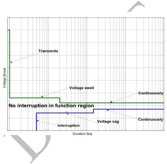
5.4.The impact of such events on all the on-site electrical power systems (AC and DC) (see Fig. 6) should be evaluated and confirmed that the allowable voltage and frequency requirements are not exceeded and the protection system is adequate.
5.5.The grid transient system stability analyses should demonstrate that the plant could ride through and remain connected to the grid for perturbations that do not result in generator falling out of step.
17
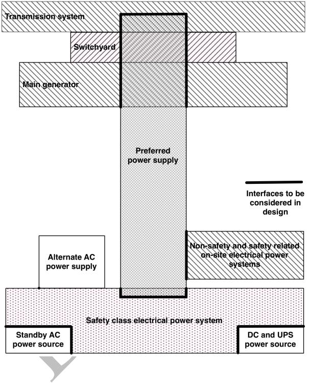
FIG. 5. Relationship between the preferred power supply and other elements of the electrical power system.
Station blackout
5.7. International operational experience has shown that loss of the preferred power supply concurrent with a turbine trip and unavailability of the emergency AC power system is a credible event. Such an event may affect a single unit, multiple units on one site, or all units on one site. Such an event is called station blackout. The term station blackout does not include the simultaneous failure of uninterruptible AC power supplies or DC power sources, or the failure of alternate AC power sources that are diverse in design and not susceptible to the events that caused the loss of on-site and off-site power sources.
18
5.8.Several design measures are possible as a means of increasing the capability of the electrical power systems to cope with a station blackout. These measures include, for example, increasing the capacity of batteries to supply power to safety instrumentation and control equipment, and to other vital equipment, use of unit to unit connections, or installing an alternate AC power source that is diverse in design and protected from elements that can degrade the normal and standby power sources.
5.9.The plant’s capability to maintain fundamental safety functions and to remove decay heat from spent fuel should be analysed for the period that the plant is in a blackout condition.
5.6.This desired defence in depth capability supports the preferred power supply operation.
FIG. 6. Voltage swell and sag (note that initial conditions could be anywhere within the continuous band).
DESIGN FOR RELIABILITY
G en eral
5.13. SSR-2/1 Requirement 23 states that:
“The reliability of items important to safety shall be commensurate with their safety significance.”
5.14. In the design of electrical systems important to safety, design features such as redundancy, diversity, tolerance of random failure, independence of equipment and systems, tolerance of common
19

cause failures, testability and maintainability, fail-safe design, and selection of high quality equipment,
are typically used to provide the specified reliability of safety functions.
R ed u n d an cy
5.15.Electrical systems important to safety should be redundant to the degree necessary to meet design basis reliability requirements.
5.16.Redundancy is commonly used in electrical power systems important to safety to achieve system reliability goals or conformity with the single failure criterion. For redundancy to be fully effective, independence is also necessary. Taken alone, redundancy increases the reliability of safety actions, but it also increases the probability of spurious operation. Coincidence of redundant signals (voting logic) or a rejection scheme for spurious signals that is based on comparisons of the redundant signals is commonly used to obtain an appropriate balance of reliability and freedom from spurious operation.
5.17.Operating experience indicates that additional redundancy within a train or division provides operational flexibility and increased availability. The availability of spare components such as an uninterruptible power supply, or battery charger, might preclude operating restrictions in the event of a failure or maintenance related outage of these critical components.
Independence
5.18. SSR-2/1 Requirement 24 states that:
“The design of equipment shall take due account of the potential for common cause failures of items important to safety, to determine how the concepts of diversity, redundancy, physical separation and functional independence have to be applied to achieve the necessary reliability.”
5.19. SSR-2/1 Requirement 21 states that:
“Interference between safety systems or between redundant elements of a system shall be prevented by means such as physical separation, electrical isolation, functional independence and independence of communication (data transfer), as appropriate.”
5.20. SSR-2/1 Paragraph 5.35 states that:
“The design shall be such as to ensure that any interference between items important to safety will be prevented, and in particular that any failure of items important to safety in a system classified in a lower safety class will not propagate to a system classified in a higher safety class.”
5.21. Independence is provided to prevent a failure or internal or external hazard from affecting redundant elements of safety systems. It also prevents a failure or hazard from affecting systems that provide different levels of defence in depth. Failure processes to be considered include: failures resulting from design basis events, exposure to the same internal or external hazards, failure of
20

common support systems, electrical connections between systems or divisions, data exchange between
systems or divisions, or common errors in design, manufacture, operations, or maintenance.
5.22.Safety items should be independent of the effects of the design basis accidents to which they respond.
5.23.Safety systems should be independent from systems of lower safety classification as necessary to ensure that the safety systems can perform their safety functions during and following any design basis event that requires these functions.
5.24.Redundant portions of safety groups should be independent from each other to ensure that the safety group can perform its safety functions during and following any design basis event that requires these functions.
5.25.Failure of one part of the electrical power systems, structures and components should not render other parts inoperable when they are required to function.
5.26.The functional failure of the support features of safety systems should not compromise the independence between redundant portions of safety systems or between safety systems and systems of lower safety classification.
5.27.For example, assigning a safety system support feature such as room ventilation to the same division as the safety system it supports prevents the loss of mechanical function in one division causing a loss of electrical system function in another division.
5.28.Means for providing independence include physical separation, electrical isolation, independence from the effects of communications errors, equipment qualification, and diversity. Generally a combination of these methods is applied to achieve independence goals.
5.29.When isolation devices are used between systems of different safety importance, they should be a part of the system of higher importance.
5.30.Measures used to provide isolation from various physical effects, electrical faults and communications errors do not necessarily need to be in the same physical device or at the same location in a circuit. Isolation functions for a single effect may also be shared by more than one device.
5.31.The adequacy of design features provided to meet the independence requirements should be justified.
21

Physical separation
5.32. Physical separation:
•Protects against common cause failure due to the effects of internal hazards. Internal hazards of concern include: fire, missiles, steam jets, pipe whip, chemical explosions, flooding, and failure of adjacent equipment.
•May be used to protect against common cause failure due to normal, abnormal, or accident environments, the effects of design basis accidents, or the effects of internal and external hazards. Environmental, seismic, and electromagnetic qualification may also be used by themselves, or in conjunction with physical separation, to protect against the effects of accidents, internal hazards, or external hazards.
•Might reduce the likelihood of common cause failures as a result of events that have localized effects (e.g., tornado, tsunami, or aircraft impact).
•Reduces the likelihood of inadvertent errors during operation or maintenance on redundant equipment.
5.33.Physical separation is achieved by barriers, distance or a combination of the two.
5.34.NS-G-1.7, Ref [7] and NS-G-1.11, Ref. [8] give guidance on protection against fires and other internal hazards.
5.35.Items that are part of safety systems should be physically separated from items of lower safety classification.
5.36.Redundant portions of safety groups should be physically separated from each other.
5.37.Some areas that might present difficulties due to convergence of equipment or wiring are:
•Containment penetrations,
•Motor control centres,
•Switchgear areas,
•Cable spreading rooms,
•Equipment rooms,
•The main and other control rooms, and
•The plant process computer.
Electrical isolation
5.38. Electrical isolation is used to prevent electrical failures in one system from affecting connected systems. Electrical isolation controls or prevents adverse interactions between equipment and
22

components caused by factors such as electromagnetic interference, electrostatic pickup, short circuits,
open circuits, grounding, or application of the maximum credible voltage (AC or DC).
5.39.In general, non-safety loads should not be powered by safety electrical power systems.
5.40.If it is necessary to power non-safety loads from the safety electrical power systems they should be isolated by safety classified isolation devices.
5.41.Non-safety loads should preferably be disconnected from the safety electrical power systems when supply is transferred to safety standby AC power sources.
5.42.Non-safety loads that remain connected should be analysed for worst case fault and catastrophic failure modes.
5.43.Non-safety loads that remain connected during postulated accident conditions should be included in power system loading analyses.
5.44.Fault current and failure mode evaluation should demonstrate minimal or no impact on associated safety systems.
5.45.An example of a preferred isolation device is a circuit breaker that is automatically tripped by an accident signal or loss of voltage signal generated within the same safety division as the isolation device. This type of design feature precludes adverse impact (such as short circuit current) on the safety power supplies.
5.46.Redundant divisions of safety classified electrical power systems should not be interconnected.
5.47.Connections between redundant divisions may be made during operation if a safety assessment confirms the reliability of a power supply is increased significantly and sufficient independence of the redundant divisions is ensured.
5.48.Connections between redundant divisions may be made during shutdown after a safety assessment confirms the following:
•The interconnections have interlocks that cannot be defeated by simple switch operation; and
•The effect of these connections on the reliability of plant safety functions and their vulnerability to common cause failure is acceptable.
5.49.These interconnections could also be used in station blackout conditions.
5.50.Examples of provisions for electrical isolation include circuit breakers, relays, electronic isolating devices, optical isolating devices (including optical fibre), cable or component shielding, separation distance, internal mechanical structures, or combinations of them.
5.51.Qualification for electromagnetic compatibility complements electrical isolation by protecting against electromagnetic interference and electrostatic pickup.
23

Associated circuits
5.52. When it is impractical to provide adequate physical separation and isolation from electrical faults between a safety circuit and a circuit of a lower class function, the lower class circuit (associated circuit) should be:
a.Analysed or tested to demonstrate that the association does not unacceptably degrade the safety class circuits with which it is associated,
b.Identified as part of the safety division with which it is associated, and
c.Physically separated from other components in the same manner as the circuits of the safety division with which it is associated.
D iv ersity
5.53.Safety power systems should be supplied from diverse power supplies.
5.54.Diversity in power sources is usually inherent in the architectural design of the power system.
5.55.Typically safety power system loads can be supplied from:
•The off-site power system, via the preferred power supply;
•The main generator, which is the normal power source and in-house load scenarios will supply power;
•The standby power source, which will supply the safety power systems on loss of off-site power; or
•Alternate AC power source during station blackout conditions.
5.56.DC loads can be supplied from batteries or (via rectifiers) from any of the above sources.
5.57.Uninterruptible AC power system loads can be supplied from batteries or battery chargers (via inverters) or from safety system AC buses using bypass switches.
5.58.Where the design basis requires diversity for software based devices of an electrical power system, the guidance of DS-431, Ref. [3] should be followed.
5.59.Diversity of power supply sources for specific loads, e.g., I&C systems, might often improve the availability of the overall system.
5.60.If diverse non-electrical power systems are provided to accomplish a given safety function, their power supplies and their instrumentation and control systems should be independent of the power sources and instrumentation of the diverse power systems (electrical or other non-electrical).
5.61.This recommendation applies to multiple non-electrical systems that are diverse as well as nonelectrical power systems that are provided for diversity from electrical power systems (such as steam or engine driven pumps).
24

5.62. In addition to physical separation and electrical isolation, diversity might be necessary to achieve independence between redundant systems or between systems supporting different levels of the defence in depth concept. This may be achieved by the use of dedicated power sources or by supply from uninterruptible power supplies.
Common cause failures
5.63. SSR-2/1 Requirement 24 states that:
“The design of equipment shall take due account of the potential for common cause failures of items important to safety, to determine how the concepts of diversity, redundancy, physical separation and functional independence have to be applied to achieve the necessary reliability.”
5.64.The possibility of common cause failures, which could render the safety power systems unavailable to perform their safety functions when called upon, should be considered in the design, maintenance, testing and operation of the safety power systems and their support systems.
5.65.The principles of diversity and independence (physical separation and functional isolation) should be applied to protect against credible common cause failures originating either within the equipment of the safety system itself, switching surges or voltage/frequency excursions from connected systems or from human involvement (e.g. in operations and maintenance).
5.66.The use of principles of independence helps to ensure, but does not fully guarantee, that common cause failures will not be the primary cause to system unavailability.
5.67.As the nuclear power plant is connected to one transmission system, one event on the grid could influence redundant parts of the safety power systems. If the nuclear power plant has two turbines and two generators, the common cause failure possibilities will decrease. If the redundant safety power systems are fed from independent connections to the grid the common cause failure possibilities will also decrease.
5.68.Operating experience of events related to voltage transients, both on off-site and on-site power supplies, has demonstrated the need for increased attention to the design of the electrical power systems in order to minimize the risk for common cause failures. A ‘no interruption’ concept is desirable, realized as a series of design means to minimize the impact from transients (see Fig. 6).
5.69.Due to the voltage, frequency and phase angle excursions that can occur in a generating facility, operating experience from industrial applications is of limited value when screening for common cause failure vulnerability.
5.70.The primary protections against common cause failures originating from the grid are:
•Comprehensive design bases and guidelines that identify all possible events that could challenge the safety power systems;
25