


Project 4
We also learned how to add a media file to our Twitter status update. In this sketch, the media file was the image of the smiley that we created.
Mission Accomplished
Our mission was to implement a sketch that makes it easier to communicate the current emotional status of a user. We have accomplished this by creating a smiley that has various controllable facial parameters. In task 1, we implemented the drawing routine that generates our smiley, but changing the parameters meant changing a variable and running the sketch again.
To tackle this problem, we added some GUI elements to our sketch in task 2 to simplify the interaction with our sketch for the user. We didn't use any existing GUI libraries, but instead created the sliders from scratch by implementing the mouse event callback functions and drawing some rectangles.
In task 3, we created the necessary code to authenticate our app with twitter.com and created a method that allows our app to post status updates for a Twitter user. We created a consumer key and a consumer secret key on the Twitter developer site and asked the user for permission to tweet using a request URL and pin code.
And finally, we combined the two sketches in task 4 by adding a button to our GUI that tweets a status message on Twitter and adds the face the user has adjusted. We created an image containing the smiley by sparing the GUI elements and copying only a section of the sketch window to a new PImage object; we then saved this file and added it as a media object to the status update.
You Ready to go Gung HO? A Hotshot
Challenge
The Smilie-O-Mat is finished, but this doesn't mean you have to stop here. Why don't you try to take it to the next level and implement one of the following suggestions:
ff Parse the Twitter stream for the #SmilieOMat messages of people you follow
ff Make additional facial features changeable
ff Create a mobile version
ff Publish your smiley on other social networks
109

Project 5
The Smilie-O-Mat
Controller
The invention of mouse and graphical user interfaces at Xerox PARC was a groundbreaking event in computer history. The mouseis a very versatile mechanism of interacting with a computer, and it enabled a whole range of new methods for data entry and controlling the program flow. But if a tool is usable on a very broad range of problems, it generally means that it isn't optimized for any of them. Some programs are easier, faster, or more ergonomically usable with a specialized controller. In this mission, we are going to create a customized controller for our Smilie-O-Mat sketch, which we created in Project 4, Smilie-O-Mat.
Mission Briefing
Our current mission is to build a custom controller for the Smilie-O-Mat sketch we wrote in the previous project. We will make use of an Arduino board (an inexpensive board using an AVR microcontroller), a button, and some variable resistors. We will connect the Arduino board to our computer through USB and create a simple protocol for controlling the facial parameters of our smiley.
Why Is It Awesome?
As already mentioned in the introduction, the mouse is a great and versatile input device, but sometimes it's not the best one available. Drawing an image is far more fun with a pressure-sensitive tablet, playing racing games is more fun with a steering wheel and some pedals, and making music is far easier with a keyboard controller, just to name a few examples. Sometimes we need a specialized controller to interact in a faster or more natural way with our data or our processes.

The Smilie-O-Mat Controller
Knowing how to interface sliders, buttons, and knobs with a computer, enables us to optimize our workspace and workflow exactly the way we need and want it.
Your Hotshot Objectives
Our current mission consists of four tasks. We are starting with a simple "hello world" circuit and extending it until we have a working controller board for our Smilie-O-Mat sketch, and then building a housing for it. The task list for our current mission is as follows:
ff
ff
ff
ff
Connecting your Arduino
Building your controller
Changing your face
Putting it in a box
Mission Checklist
To build the controller, we will need an Arduino board, a solderless breadboard, and a handful of electronic components, as follows:
ff
ff
ff
ff
ff
ff
Arduino
Breadboard
Wires
A push button
A resistor (10 kOhm)
Three variable resistors (100 kOhm)
In the final task of this mission, we will create a permanent housing for the controller using a box and some fancy knobs. I will also provide a list of materials that I have used in this section, but similar to the robots in Project 1, Romeo and Juliet, the housing is very much a matter of taste.
Connecting your Arduino
Say hello to your Arduino. The first task of our current mission is to write a sketch that runs on Arduino and reads the value of a variable resistor. Since this is a book about Processing, we are going to write a Processing sketch that receives the resistor values from our Arduino board and prints the value.
 112
112
Project 5
Prepare for Lift Off
In this task, we are going to write code that runs on Arduino, so we need the Arduino IDE installed. You can download it from www.arduino.cc and install it by unzipping the package that matches your operating system.
Engage Thrusters
Let's hook up our Arduino:
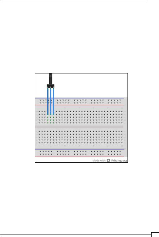
1.The first thing we need to do for this task is to build a little circuit, so take one of your variable resistors and hook it up to the solderless breadboard like in the following diagram:
2.Now connect a red wire from the 5V pin of your Arduino board to one of the outer leads of our resistor.
3.The middle pin of the resistor gets connected to the pin labeled ANALOG IN 0 on your Arduino board.
113
The Smilie-O-Mat Controller
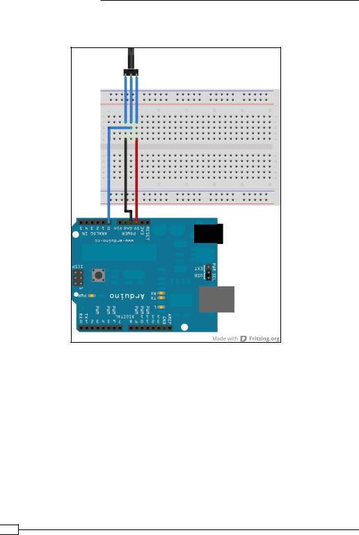
4.Connect a black wire from the Gnd pin of your Arduino to the remaining pin of your resistor. Your connections should look as shown in the following diagram:
5.Now connect your Arduino board to a USB port in your computer and start the Arduino IDE.
6.Make sure that the correct serial port is selected by checking the Tools | Serial Port menu, and the correct Arduino board type is selected by checking the Tools |
Board menu.
7.Our first Arduino sketch will use the built-in LED of Arduino. We'll use the variable resistor that we've just added to control the blinking speed of the LED. Now, we will add the following code to the Arduino sketch and save it:
int del = 5;
boolean state = true;
 114
114

Project 5
void setup() {
pinMode( 13, OUTPUT ); Serial.begin( 9600 );
}
void loop() { if ( state ) {
digitalWrite( 13, HIGH ); } else {
digitalWrite( 13, LOW );
}
delay( del ); state = !state;
del = analogRead( 0 );
}
8.Verify the code by clicking on the verify icon, and if everything compiles well, click on the upload button to install the code on your Arduino.
9.Turn the knob of your variable resistor and check the blinking speed of the LED.
10.Now we want Arduino to send the value of the variable resistor to the computer using a serial port. Add the following line of code to the setup() method of the Arduino sketch to initialize the serial port and set its speed as follows:
void setup() {
pinMode( 13, OUTPUT ); Serial.begin( 9600 );
}
11.In our loop() method, we print the value of the resistor using the println() method of the Serial object. We also remove the LED blinking code and the delay from our sketch:
void loop() {
del = analogRead( 0 ); Serial.println( del );
}
12.Compile and install the sketch on Arduino by clicking on the verify and upload icon.
13.Now we need to open the serial console to see what values the Arduino is sending. Use the Tools | Serial Monitor menu to see the serial console and turn the knob of your resistor, and then watch the values change on the console.
115

The Smilie-O-Mat Controller
14.Currently, the resistor value is sent every time the Arduino runs through the main loop, but most of the time the value hasn't changed. So let's send the value only if there is a change by storing the last value we have sent and comparing it to the current value.
int del = 5; int lastDel = d;
void loop() {
del = analogRead( 0 );
if (abs( del - lastDel ) > 10 ) { Serial.println( del );
lastDel = del;
}
}
15.Compile and upload the code to Arduino and open the serial console. If you turn your knob now, you will see the changed values, but if you leave it as it is then no values will be sent.
16.Now we have finished the Arduino part of our first task, let's switch to the Processing half of it. Open Processing, create a new sketch, and add the setup() and draw() methods:
void setup() {
}
void draw() {
}
17.To communicate with our Arduino, we need to import the serial library, which enables us to use the serial port in our processing sketch. So, use the Sketch | Import Library … | serial menu to import the library.
We create an instance of the serial port object and define a string where we can store the text lines we read from the serial port:
import processing.serial.*;
Serial port;
String str = "";
18.Then, we add the following code to our setup() method to initialize the serial port and define a font. Be sure to use the same name for the serial board we have used in the Arduino IDE in step 6. In this case, it's /dev/ttyUSB0.
void setup() { size( 300,300 );
 116
116
Project 5
port = new Serial( this, "/dev/ttyUSB0",", 9600); textFont( createFont( "Sans", 64 ));
}
19. In our draw() method, we simply write out the content of the string variable:
void draw() { background( 255 ); fill(0);
text( str, 20, 100 );
}
20.Now, we add a callback method named serialEvent() that gets called every time the serial port detects an activity. We are reading a string from the current buffer until we find a newline character, and then we store it in our string variable:
void serialEvent( Serial p ) {
String in = p.readStringUntil( '\n' ); if ( in != null ) {
str = in;
}
}
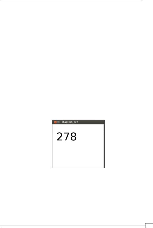
21.Now, connect your Arduino and start your Processing sketch. Turn the knob and watch the values change. Your sketch window should look like the following screenshot:
Objective Complete - Mini Debriefing
For this first task of our current mission, we created an Arduino sketch that runs on a microcontroller and reads the value of a variable resistor. We created a simple circuit to hook up the resistor to Arduino. Then, from step 1 to step 9, we made our sketch read the value of the resistor and use this value to change the blinking speed of the built-in LED. Once this code is installed on the microcontroller, it runs independently from any computer and uses the USB cable only as a power source. If you would disconnect the USB cable and power the Arduino board using an AC adapter or a battery, your sketch still would run.
117