

ManualOperator
.pdfRoutes
Routes Center
All your Routes are displayed in the Routes Center, and they are automatically saved in a database. The first time you launch the software, the Routes Center is empty. You can create or import as many routes as you wish.
 To call up the Routes Center select [Centers] from the [Route] menu and choose [Routes]
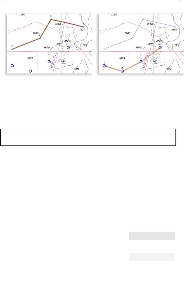
The Routes Center window appears at the bottom of the screen and lists all previously created routes. Click on the box to the left of any route to select the route you want to work with. Once a route is selected, the box to the left of that route will turn blue. Simultaneously the route is selected and colored in orange in the Center and on the Chart. When a Route is selected, all details about the trip are reported in the Selected Route Center.
TIP - You can also select the Route directly on the chart by clicking on it with the Finger Tool
The Routes Center has a Toolbar that allows you to do specific tasks :
 Use this button to un-select the route
 Use this button to center the chart on the selected route
 Use this button to access and modify the properties of the Center
 Use this button to display the Route Properties dialog box
 Use this button to search for a route that contains specific key-words or terms in the Center
•Use the Sort Menu to sort routes according to specific parameters. Note that you can also double click directly on the Column Title
•Use the Action Menu to perform specific actions like reverse, delete or export the selected route
49
MaxSea Operator Manual version 12.6
Fig.1 |
Fig.2 |
|
|
Route created using QuickWaypoints |
Route created using existing Waypoints (made with the Pen |
|
Tool) |
|
|
 Only one route can be selected at a time.
TIPS - Double-click on a line to display the appropriate Center (Planning or Active Route Center.) Use the Right-click on a line for displaying the Contextual menu.
Routes Properties
 How to Display Each Route Properties dialog :
Under the Routes Center, select a route and click the Properties button on the Center toolbar or use the right-click menu on a chosen line.
Then the "Routes Properties" dialog appears on screen and gives you the possibility to enter:
1.A route's name to easily and quickly retrieve it in the Routes Center list.
2.A started point location's name and destination location's name.
|
Routes attributes |
|
|
Description |
|
Default value |
|
|
|
|
|||
|
|
|
|
|
|
|
|
FID* |
|
|
This number is the route identifier in the software and it |
|
|
|
|
|
|
is automatically attributed when you create a new |
|
|
|
|
|
|
route. It is unique and stored in your Routes database. |
|
Software attribute |
|
|
|
|
|
|
|
|
|
|
|
|
|
|
50
Routes
|
Name |
|
To assign a own name of a route. |
User's attribute |
||
|
|
|
|
|
|
|
|
|
|
|
|
|
Empty by default |
|
|
|
|
|
|
|
|
From |
|
To enter a name for |
the started point route. |
User's attribute |
|
|
|
|
|
|
|
|
|
|
|
|
|
|
Empty by default |
|
|
|
|
|
|
|
|
To |
|
To enter a name for |
the point route destination. |
User's attribute |
|
|
|
|
|
|
|
|
|
|
|
|
|
|
Empty by default |
|
|
|
|
|
|
|
|
Comments |
|
It is Where you can apply an own annotation |
User's attribute |
||
|
|
|
|
concerning a route. |
|
|
|
|
|
|
|
|
|
|
|
|
|
|
|
Empty by default |
|
|
|
|
|
|
|
|
GPS / NN Name * |
|
|
If the route is a downloaded route from a GPS, MaxSea |
|
|
|
|
|
|
will create a FID number and keep the GPS identifier |
GPS identifier |
|
|
|
|
|
(GPS ID). |
|
|
|
|
|
|
|
|
|
|
GPS / NN |
|
|
As line above, this information provided from the GPS |
GPS comments |
|
|
Comments * |
|
|
can not be modified. |
|
|
|
|
|
|
|
||
|
|
|
|
|
|
|
(*)all data information in a cell colored in grey are defined by default and can't be modified.
Selected Route Center
If you have just drawn or selected a Route, the Selected Route Center allows you to view details (like leg distance, time to go, total distance) and enter some information about the Route (like estimated speed and date.) The Selected Route will appear graphically on the chart colored in orange.
To open the Selected Route Center, select [Centers] and choose [Selected Route] from the [Route] menu.
Note that the Selected Route Center is empty if no Route is selected. See also related topics for getting information on "How to create a Route" and "How to select a Route".
The Planning Route Center consists in a route plan report. Each line gives information about :
•A Waypoint and its associated leg.
•Distance and bearing information such as Total Distance, Leg Distance and COG
•Constraint values (ETA and SOW) that can be set by the user
•Not modifiable values (gray) such as TTG and Total TTG that depend on constraint values
TIPS - A leg in the selected route center colored light blue indicates that a constraint value has been entered. This means that information such as estimated speed or ETA have been set by the operator. MaxSea will then use these parameters to calculate the other leg / route parameters. To free a constraints and set to default, right click on the line (leg) and choose "Free Constraints."
How to print Route Information:
51
MaxSea Operator Manual version 12.6
•Select the Action Menu and choose "Print"
•Or right-click on the Center and choose "Print"
TIPS - You can also select the Action Menu to Copy the Center to the Clipboard and paste it in Excel. This will allow you to edit the layout and remove unwanted information.
How to move in the Planning Route Center (by using the mouse or the keyboard):
•Vertically or Horizontally navigation into the Planning Route Center, use the arrows on the keyboard.
•The selected line appears surrounded with dotted line.
To change the "Planning Route Center" table display configuration:
•Click the "Grid Option" button to configure the table:
1.To Hide or show desired columns by checking appropriate boxes
2.To Move columns in the Planning Route Center click on UP or Down
•Change the order of column
1.Click on the Title of the Column to select it
2.Drag it to the new position
IMPORTANT - After each modification, the values of the route plan are immediately updated. Please make sure to choose the DOT (not comma) when entering decimal values.
Selected Route Leg Properties
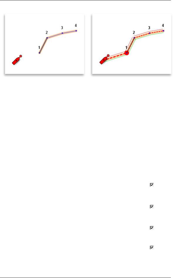
 Each line along a route between two waypoints is known as a Leg. The Leg Properties dialog depends on the category of the selected Route. There are two sorts of Leg, the Planning Leg drawn in orange and the Active Leg drawn in red on the chart. The Active Leg consists of your boat traveling (see related topic on Activating a Route for more information) and the Planning Leg is your draft. You can easily edit each Leg of Selected Route after placing it on the chart. A Selected Leg can be customized as many time needed, and MaxSea enables to create as many back-up routes with the Duplicate function as you wish.
52
Routes
Fig. 1 shows you the selected Leg of a planning route |
Fig.2 shows you the selected Leg of the active route between |
between the Quickwaypoint (1) and (2). |
the waypoints (1) and (2). |
|
|
After plotting a route on a chart, you can use the Properties dialog to calculate the speed of each selected leg, to edit waypoint position and others data values, to estimate the arrival time (ETA) and speed over water (SOW) of the trip, to define the waypoint approaches such as the auto scale value, "Out of limits" positioned ( XTE) and passage mode.
Select a Route Leg to edit and modify Properties
1.Under the chart display, double left-click with the Select tool a Lef on along the Route or apply a long click on a leg and the quick link.
2.Under the Selected Route Center list, select a line and click on the Properties button or use the right-click menu on a chosen line.
The Leg Properties dialog appears and gives following details:
|
Label |
|
Definitions |
Value by default |
|
Column displayed by |
|
|
|
default |
|||
|
|
|
|
|
|
|
|
|
|
|
|
|
|
#Leg |
|
Seq Number corresponds |
|
|
|
|
|
|
|
to the Route Leg is the |
Software attribute |
|
|
|
|
|
segment of a route |
|
|
|
|
|
|
between two waypoints. |
|
|
|
|
|
|
identifier in MaxSea. |
|
|
|
|
|
|
|
|
|
|
Leg. Dist |
|
Leg Distance - distance |
|
|
|
|
|
|
|
between two waypoints. |
Software attribute |
|
|
|
|
|
|
|
|
|
|
|
|
|
|
|
|
Total Dist |
|
Total Distance - additional |
|
|
|
|
|
|
|
distance between the first |
Software attribute |
|
|
|
|
|
waypoint and the last |
|
|
|
|
|
|
waypoint. |
|
|
|
|
|
|
|
|
|
|
#WP |
|
Waypoint Identifier number |
|
|
|
|
|
|
|
in MaxSea. |
Software attribute |
|
|
|
|
|
|
|
|
|
|
|
|
|
|
|
|
53

MaxSea Operator Manual version 12.6
WP Name |
Name associated to |
Software attribute |
|
|
waypoint. See related topic |
|
|
|
Waypoints Label glossary |
|
|
|
to modify it. |
|
|
|
|
|
|
WP Lat/Lon |
Geographical position |
|
|
|
drawn by a point on your |
|
|
|
chart. See related topic |
When creating waypoint |
|
|
Waypoints Label glossary |
|
|
|
|
|
|
|
to modify geographic |
|
|
|
positions. |
|
|
|
|
|
|
Scale at WP |
Change of scale occurs |
|
|
|
when getting into the |
|
|
|
Waypoint arrival circle. For |
Active Chart Scale.. |
|
|
more details see related |
|
|
|
|
|
|
|
topic: Waypoint Auto-Scale |
|
|
|
function |
|
|
|
|
|
|
ETA |
Estimation Time Arrival - |
attribut logiciel |
|
|
Software calculation with |
|
|
|
present date and speed of |
|
|
|
the vessel. |
|
|
|
|
|
|
TTG |
Time To Go - The amount |
|
|
|
of time estimated until the |
|
|
|
vessel reaches an active |
Software attribute |
|
|
waypoint, assuming no |
|
|
|
|
|
|
|
intervening change in |
|
|
|
course or speed. |
|
|
|
|
|
|
Tot TTG |
Total Time To Go - The |
|
|
|
total amount of time |
|
|
|
estimated until the vessel |
|
|
|
reaches from the first |
|
|
|
waypoint to the last |
Software attribute |
|
|
Waypoint. |
|
|
|
|
|
|
COG |
Course Over Ground - the |
|
|
|
direction, reported in true |
|
|
|
or magnetic north values, |
Data coming from |
|
|
in which a GPS receiver |
|
|
|
and the person operating it |
instrument |
|
|
are moving with respect to |
|
|
|
the earth. |
|
|
|
|
|
|
CTS |
Course To Steer - is the |
|
|
|
direction to reach the COG |
|
|
|
with taking into account the |
Software attribute |
|
|
currents values (waves, |
|
|
|
currents, ...). |
|
|
|
|
|
|
54
Routes
SOG |
Speed Over Ground - it is |
|
|
the actual fixed geographic |
|
|
speed of a vessel. It is |
|
|
essentially the Speed over |
|
|
Water (SOW), plus the |
|
|
cumulative effect of wind |
5 Nm |
|
and current. |
|
|
|
|
|
|
|
SOW |
Speed Over Water |
5 Nm |
|
|
|
|
|
Fuel |
Details of Fuel |
Software attribute |
|
|
Consumption |
|
|
|
|
|
|
Tot. Fuel |
Additional Fuel |
Software attribute |
|
|
Consumption |
|
|
|
|
|
|
Current Dir |
Current Direction |
Data coming from |
|
|
|
instrument |
|
|
|
|
|
Current Speed |
Current Speed |
Data coming from |
|
|
|
instrument |
|
|
|
|
|
Leg Dist |
Leg Distance - distance |
Software attribute |
|
|
between two waypoints. |
|
|
|
|
|
|
Tot Dist |
Total Distance - additional |
|
|
|
distance between the first |
|
|
|
waypoint and the last |
Software attribute |
|
|
waypoint. |
|
|
|
|
|
|
|
|
|
|
AWS |
Apparent Wind Speed - |
|
|
|
When the vessel is in |
|
|
|
motion, onboard wind |
Data coming from |
|
|
speed measurements - the |
|
|
|
AWS - will differ from |
instrument |
|
|
stationary measurements |
|
|
|
(True Wind Speed, or |
|
|
|
TWS). |
|
|
|
|
|
|
55

MaxSea Operator Manual version 12.6
TWS |
True Wind Speed - When |
|
|
|
the vessel is in motion, |
|
|
|
onboard wind speed |
Data coming from |
|
|
measurements - the AWS - |
|
|
|
instrument |
|
|
|
will differ from stationary |
|
|
|
|
|
|
|
measurements (TWS). |
|
|
|
|
|
|
TWA |
True Wind Angle |
Data coming from |
|
|
|
instrument |
|
|
|
|
|
TWD |
True Wind Direction - In |
|
|
|
order to overcome the |
|
|
|
effects of drift and wind, a |
|
|
|
vessel which is trying to |
|
|
|
reach a given waypoint |
|
|
|
may not bear straight |
Data coming from |
|
|
towards it. As a result, |
instrument |
|
|
onboard wind direction |
|
|
|
measurements - the AWD - |
|
|
|
may not be the same as |
|
|
|
the True Wind Direction |
|
|
|
(TWD). |
|
|
|
|
|
|
VMG |
Velocity Made Good - The |
|
|
|
speed at which the vessel |
|
|
|
is moving toward its |
Data coming from |
|
|
intended destination, |
instrument |
|
|
regardless of the vessel's |
|
|
|
direction. |
|
|
|
|
|
|
VMC Max |
Maximum Velocity Made |
|
|
|
Course - equivalent to the |
|
|
|
current speed towards the |
|
|
|
waypoint in comparison to |
|
|
|
the potential speed (as |
|
|
|
protracted by the current |
|
|
|
polar). |
|
|
|
|
|
|
CMG Max |
Course Made Good |
|
|
|
|
|
|
Opt Tack A |
Optimum Tack Angle, |
|
|
|
When navigating close- |
Software attribute |
|
|
hauled for example. |
|
|
|
|
|
|
Opt Tack Hdg |
Optimum Tack Heading |
Software attribute |
|
|
|
|
|
|
|
|
|
Vitesse Opt. Tgt Spd |
Target Speed |
Data coming from |
|
|
|
instrument |
|
|
|
|
|
TOD |
Time Of Departure |
Data coming from |
|
|
|
instrument |
|
|
|
|
|
FID_ROUTE_CATALOG |
Route Identifier. see |
When creating a route |
|
|
related topic: Routes |
|
|
|
Center. |
|
|
|
|
|
|
56

Routes
XTE |
Cross Track Error - The |
|
|
|
distance of a line drawn |
|
|
|
from the vessel |
|
|
|
perpendicularly to an active |
|
|
|
route leg. This determines |
|
|
|
to what extent the vessel is |
|
|
|
straying from the course of |
|
|
|
a route. |
0,000 Nm |
|
|
|
|
|
|
For more details see |
|
|
|
related topic: "Out of limits" |
|
|
|
positioned" |
|
|
|
|
|
|
Mode Passage |
Trois modes de passage |
|
|
|
disponibles: |
|
|
|
En Distance, |
|
|
|
Par la Perpendiculaire, |
Distance + Par la |
|
|
|
|
|
|
En Distance + Par |
Perpendiculaire |
|
|
|
|
|
|
Perpendiculire |
|
|
|
|
|
|
Color |
Available when GPS |
|
|
|
requires color information. |
GPS Attribute |
|
|
|
|
|
|
|
|
|
Symbol |
Available when GPS |
|
|
|
requires symbolic |
GPS Attribute |
|
|
representation information. |
|
|
|
|
|
|
Notes :
(1)- all data in gray cells can not be updated
(2)- data values in blue cells correspond to constraint values. To free a constraints and set to default, right click on the line (leg) and choose "Free Constraints."
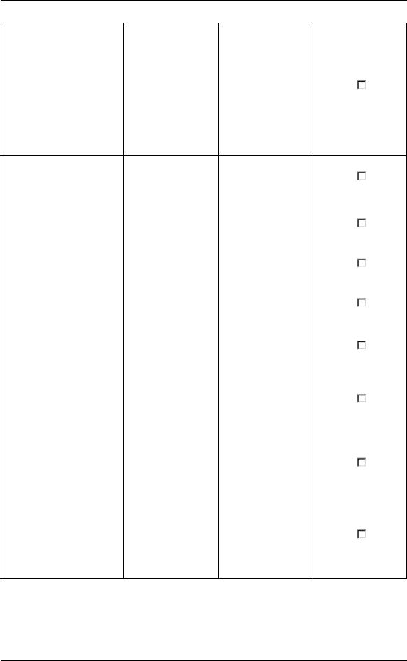
Edit & Modify the Route
Edit and Modify a Route
Thanks to the MaxSea Toolbar, it is very easy to edit Routes and Waypoints.
These Tool are used to:
1.Add Waypoints to a Route
2.Move Waypoints/Routes
57
MaxSea Operator Manual version 12.6
3. Cut the Selected Route in Two Parts
4. Delete Waypoints
Fig.1
 Note: Edition Tools apply to the Selected Route
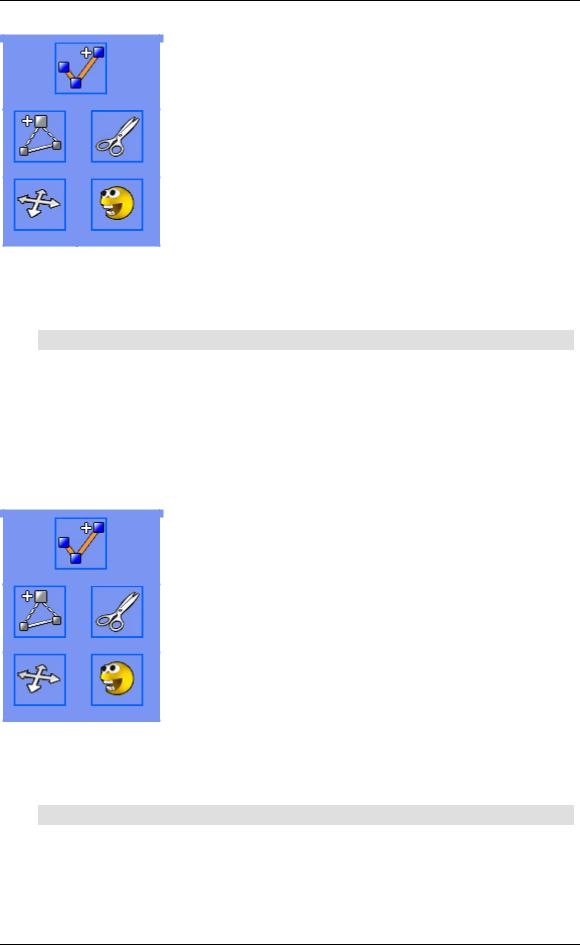
Edit and Modify a Route
Thanks to the MaxSea Toolbar, it is very easy to edit Routes and Waypoints.
These Tool are used to:
1. Add Waypoints to a Route
2. Move Waypoints/Routes
3. Cut the Selected Route in Two Parts
4. Delete Waypoints
Fig.1
 Note: Edition Tools apply to the Selected Route
58