

4F27E
.pdfTechnical Service Information
TRANSAXLE RANGE SENSOR WIRE SCHEMATIC
1 |
2 |
3 |
4 |
5 |
5 |
4 |
3 |
2 |
1 |
6 |
|
7 |
8 |
9 |
9 |
|
8 |
7 |
6 |
Transaxle Range |
Vehicle Harness Connector |
||||||||
Sensor Connector |
|||||||||
(Face View) |
|
|
(Face View) |
|
|||||
FUSE 9
20A
Ignition |
Transaxle Range |
|
Power Hold Relay |
Sensor Connector |
|
|
||
Battery Junction Box |
|
|
|
Green/Orange |
|
PCM |
1 |
|
Green/White |
||
Green/White |
||
7 |
3 |
|
|
1 |
|
Green/Orange |
Green/Orange |
|
8 |
7 |
|
|
2 |
|
Green/Black |
Green/Black |
|
11 |
2 |
|
|
D |
|
Green/Blue |
Green/Blue |
|
4 |
4 |
|
|
R |
|
|
Green/Yellow |
|
|
5 |
|
|
P |
|
|
Green/Red |
|
Back-up Lamps |
8 |
|
N |
||
Green/Yellow |
|
|
64 |
|
|
|
P |
|
Starting System |
Gray |
|
9 |
||
PCM |
N |
|
See |
||
Transaxle Range |
||
Page 10 |
Sensor
Transaxle Range
 Sensor
TRS |
|
Pin No. |
Function |
1 |
Voltage Power |
2 |
Drive Signal |
3 |
1st Signal |
4 |
Reverse Signal |
5 |
P/N Signal |
6 |
Starting System |
7 |
2nd Signal |
8 |
P/N Signal |
9 |
Starting System |
6 |
Gray/Red |
Starting System |
Copyright © 2004 ATSG
Figure 10
12 |
AUTOMATIC TRANSMISSION SERVICE GROUP |
|

Technical Service Information
ELECTRONIC COMPONENT DESCRIPTION
ELECTRONIC PRESSURE CONTROL (EPC) SOLENOID
The EPC Solenoid is located in the valve body in the location shown in Figure 4, and is a Variable Force Solenoid. A VFS solenoid is an actuator that combines a solenoid and a regulating valve.
The PCM varies the amount of current sent to the EPC solenoid, which varies pressure in hydraulic circuits affecting line pressure. Less current results in higher line pressure. Refer to Figure 5 for the resistance chart for all solenoids and Figure 6 for a complete wiring schematic.
SHIFT SOLENOIDS "A" AND "B"
Shift Solenoids "A" and "B" are ON/OFF solenoids (Normally Closed) that block fluid flow when OFF and allow full fluid flow when ON. They are located on the valve body, as shown in Figure 4.
The PCM affects shift valve positions by turning the shift solenoids ON or OFF. This results in full control of the transaxle in all forward speeds. Refer to Figure 5 for the resistance chart for all solenoids and Figure 6 for a complete wiring schematic.
SHIFT SOLENOIDS "C", "D" AND "E"
Shift Solenoids "C", "D" and "E" are located in the valve body in the locations shown in Figure 4. These solenoids are all Pulse Width Modulated (PWM) that vary fluid flow and pressure to apply components with PWM control strategy.
Refer to Figure 5 for the resistance chart for all solenoids and to Figure 6 for a complete wiring schematic.
ENGINE COOLANT TEMP (ECT) SENSOR
The Engine Coolant Temp (ECT) sensor monitors the temperature of engine coolant and supplies this information to the PCM. The resistance value of the ECT sensor varies with temperature change. The PCM monitors the voltage across the ECT sensor to determine engine coolant temperature.
The ECT is located in an engine coolant passage near the engine thermostat.
The PCM uses the ECT sensor signal to determine TCC control strategy.
AIR CONDITIONING (A/C) CLUTCH SWITCH
The PCM also monitors the AC clutch switch and when energized the PCM adjusts EPC pressure to compensate for additional load on the engine.
TRANSAXLE FLUID TEMP (TFT) SENSOR
The Transaxle Fluid Temp (TFT) sensor is located on the bottom of the fluid filter, and in contact with transaxle fluid at all times (See Figure 4).
The TFT is a temperature sensitive device called a thermister. The resistance value of the TFT sensor varies with temperature change. The PCM uses the voltage signal across the TFT sensor to determine transaxle fluid temperature.
The PCM uses the TFT sensor signal to determine whether a cold start shift schedule is necessary. The cold start shift schedule allows quicker shifts when the transaxle fluid temperature is cold.
Refer to Figure 5 for resistance values at the various temperatures and Figure 6 for a complete wiring schematic.
THROTTLE POSITION (TP) SENSOR
The Throttle Position (TP) sensor is a potentiometer mounted on the engine throttle body. The TP sensor detects the position of the throttle plate and sends this information to the PCM as a varying 0.5 to 5.0 voltage signal. The PCM uses this signal for control of the EPC pressure, the shift scheduling and TCC operation.
MASS AIR FLOW (MAF) SENSOR
The Mass Air Flow (MAF) sensor is mounted in the air cleaner inlet tube, and directly measures the mass of air flowing into the engine. The MAF sensor output is a DC voltage signal ranging from 0.5 volts to 5.0 volts and the PCM uses this signal for EPC control strategy.
BRAKE PEDAL POSITION (BPP) SWITCH
The Brake Pedal Position (BPP) switch is connected to the service brake pedal. The BPP switch has closed contacts, allowing a voltage signal to be sent to the PCM. When the brake pedal is pressed, the voltage signal is interupted and the PCM then knows to release the TCC.
Continued on Page 14
Copyright © 2004 ATSG
AUTOMATIC TRANSMISSION SERVICE GROUP |
13 |
|
Technical Service Information
TRANSMISSION CONTROL SWITCH (TCS)
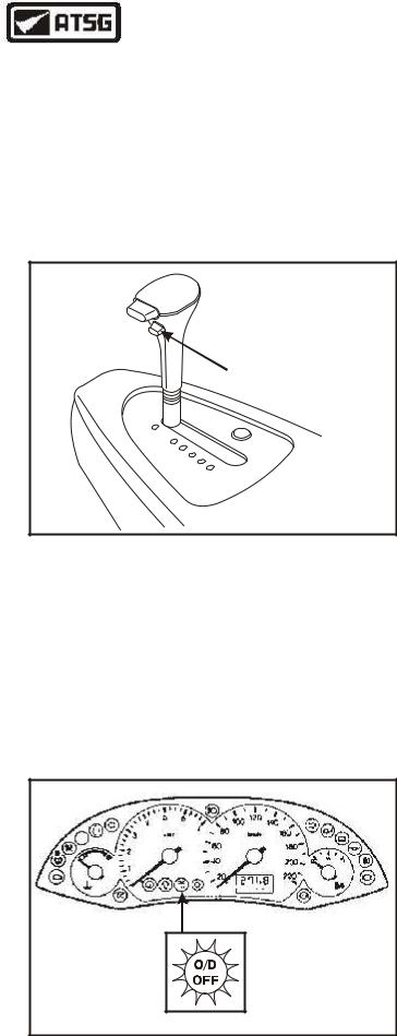
The Transmission Control Switch (TCS) is located on the manual shift lever, as shown in Figure 11, and is a momentary contact switch. When this switch is pressed, a signal is sent to the PCM to either enable or cancel 4th gear and is often called an "Overdrive Cancel Switch".
Any fault detected with the TCS causes the PCM to enable 4th gear as a default strategy.
ELECTRONIC IGNITION (EI) SYSTEM
The Electronic Ignition (EI) system is comprised of three different components, Crankshaft Position (CKP) sensor, Ignition Control Module (ICM) and the coil packs. The CKP sensor sends a signal related to the rotating speed (RPM) and position of the engine crankshaft, to the Ignition Control Module (ICM). The ICM then generates a Profile Ignition Pickup (PIP) signal that it sends to the PCM.
The PCM uses the PIP signal from the EI system to determine EPC pressure, shift scheduling and TCC control strategy.
 O/D Cancel Switch
P
R N D 2 1
Copyright © 2004 ATSG
Figure 11
TRANSMISSION CONTROL SWITCH (TCS)
The Transmission Control Indicator Lamp (TCIL) is used in vehicle applications that use the TCS. The TCIL is located on the instrument panel, as shown in Figure 12.
The PCM controls the operation of the TCIL and results in the PCM turning the TCIL ON or OFF. The TCIL is ON when overdrive is OFF.
INTAKE AIR TEMPERATURE (IAT) SENSOR
The Intake Air Temperature (IAT) sensor is located in the air cleaner outlet tube and is a temperature sensitive device called a thermister. The resistance value of the IAT sensor varies with temperature changes. The PCM monitors the voltage across the IAT to determine air temperature.
The PCM uses the IAT sensor signal to determine EPC pressure control strategy.
Copyright © 2004 ATSG
Figure 12
14 |
AUTOMATIC TRANSMISSION SERVICE GROUP |
|

|
Technical Service Information |
|
|
|
|
|
DIAGNOSTIC TROUBLE CODE CHARTS |
|
DTC |
DESCRIPTION |
|
P0705 |
Transmission Range Sensor Circuit Failure |
|
P0712 |
Transmission Fluid Temperature Sensor Circuit Grounded, 315°F Indicated |
|
P0713 |
Transmission Fluid Temperature Sensor Circuit Open, -40°F Indicated |
|
P0715 |
Turbine Shaft Speed Sensor, Insufficient Input |
|
P0717 |
Turbine Shaft Speed Sensor, Intermittent Signal |
|
P0718 |
Turbine Shaft Speed Sensor Erratic |
|
P0720 |
Output Shaft Speed Sensor, Insufficient Input |
|
P0721 |
Output Shaft Speed Sensor Erratic |
|
P0722 |
Output Shaft Speed Sensor, Intermittent Signal |
|
P0731 |
1st Gear Error - Shift Solenoid "A", "B", "C", Or Internal Parts |
|
P0732 |
2nd Gear Error - Shift Solenoid "A", "B", "C", Or Internal Parts |
|
P0733 |
3rd Gear Error - Shift Solenoid "A", "B", "C", Or Internal Parts |
|
P0734 |
4th Gear Error - Shift Solenoid "A", "B", "C", Or Internal Parts |
|
P0741 |
Torque Converter Clutch Slippage Detected |
|
P0745 |
EPC Solenoid Circuit Failure, Circuit Shorted |
|
P0750 |
Shift Solenoid "A" Circuit Failure |
|
P0751 |
Shift Solenoid "A", Mechanical Or Hydraulic Failure |
|
P0755 |
Shift Solenoid "B" Circuit Failure |
|
P0756 |
Shift Solenoid "B", Mechanical Or Hydraulic Failure |
|
P0760 |
Shift Solenoid "C" Circuit Failure |
|
P0761 |
Shift Solenoid "C", Mechanical Or Hydraulic Failure |
|
P0765 |
Shift Solenoid "D" Circuit Failure |
|
P0766 |
Shift Solenoid "D", Mechanical Or Hydraulic Failure |
|
P0770 |
Shift Solenoid "E" Circuit Failure |
|
P0771 |
Shift Solenoid "E", Mechanical Or Hydraulic Failure |
|
P1700 |
Internal Transaxle Mechanical Failure |
|
P1705 |
Transmission Range Sensor, Not In Park Or Neutral During KOEO/KOER |
|
P1711 |
Transmission Fluid Temperature Sensor, Out Of On-Board Diagnostic Range |
|
P1713 |
Transmission Fluid Temperature Sensor, No Change In Low Range |
|
P1718 |
Transmission Fluid Temperature Sensor, No Change In High Range |
|
P1746 |
EPC Solenoid Circuit Failure, Circuit Open |
|
P1747 |
EPC Solenoid Circuit Failure, Circuit Shorted |
|
P1760 |
EPC Solenoid Circuit, Intermittent Short To Ground |
|
P1780 |
Transaxle Control Switch, Input Incorrect For Selected Position |
|
P1783 |
Transaxle Overtemp Condition Indicated |
Copyright © 2004 ATSG |
|
Figure 13 |
|
AUTOMATIC TRANSMISSION SERVICE GROUP |
15 |
|
Technical Service Information
4F27E TRANSAXLE LINE PRESSURE TEST AND COOLER LINE IDENTIFICATION
"To Cooler"
"From Cooler"
|
|
|
|
|
|
llll |
|
|
|
|
|
ll |
|
|
|
|
|
l |
|
|
|
|
|
l |
|
|
|
|
|
l |
|
|
|
|
l |
l |
l |
|
|
|
|
|
|
|
|
|
||
l |
|
|
|
|
|
|
l |
|
|
|
|
|
|
l |
|
|
|
|
|
|
l |
|
|
|
|
|
|
l |
|
|
|
|
|
|
l |
|
|
|
|
|
|
l |
|
|
|
|
|
|
l |
|
|
|
|
||
l |
|
|
|
|||
l |
|
|
|
|||
|
|
l |
|
|
||
|
|
|
l |
|
|
|
|
|
|
l |
|
||
|
|
|
|
|
l |
|
l
ll |
|
|
|
|
ll |
|
|
|
|
l |
|
|
||
|
l |
|||
|
|
l |
||
|
|
l |
||
|
|
|
l |
|
|
|
|
|
l |
|
|
|
|
l |
|
|
|
|
l |
|
|
|
|
l |
|
|
|
|
l |
|
|
|
|
l |
|
|
|
|
l |
|
|
l |
l |
l |
|
l |
|
|
|
l |
|
|
|
|
l |
|
|
|
|
4F27E TRANSAXLE LINE PRESSURE TEST
RANGE |
|
IDLE |
STALL |
||||||
Park/Neutral |
|
50-65 PSI |
(345-450 KPA) |
|
|
|
|||
Reverse |
|
65-85 PSI |
(450-585 KPA) |
280-335 PSI |
(1930-2310 KPA) |
||||
D, 2, 1 |
|
50-65 PSI |
(345-450 KPA) |
180-210 PSI |
(1240-1450 KPA) |
||||
|
|
|
|
|
|
|
|
||
|
|
|
STALL SPEED CHART |
|
|
||||
|
|
|
ENGINE |
|
VIN |
|
RPM |
|
|
|
2.0L SPI (Split Port Induction) |
P |
|
2406-2811 |
|
|
|||
|
|
2.0L "Zetec"-E |
|
3 |
|
2439-2837 |
|
|
|
Copyright © 2004 ATSG
Figure 14
16 |
AUTOMATIC TRANSMISSION SERVICE GROUP |
|
Technical Service Information
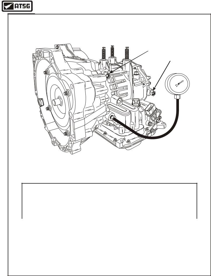
LINE PRESSURE TEST
1.Install 350 PSI pressure gauge into the line pressure tap, as shown in Figure 14.
2.Start engine and check line pressure, at idle, in each gear range and refer to the chart found in Figure 14.
Caution: If the line pressure is low at idle, "Do Not" perform the stall test, as further transaxle damage will occur.
3.Press the accelerator pedal to the floor (WOT) in each gear range and refer to the chart found in Figure 14.
Caution: Do not maintain Wide Open Throttle (WOT) in any gear range for more than five
(5) seconds.
4.Record the RPM reached in each range and compare to the stall speed chart in Figure 14.
Caution: After stall testing each gear range move the selector lever to Neutral and run the engine at 1000 rpm for about 15 seconds to allow the converter to cool, before testing the next gear range.
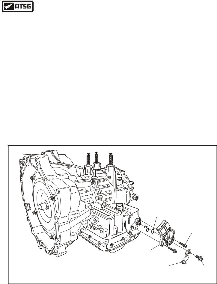
TRANSAXLE DISASSEMBLY
EXTERNAL COMPONENTS
1.Remove the external shift lever retaining bolt and external shift lever, as shown in Figure 15.
2.Remove the 2 transaxle range sensor retaining bolts, as shown in Figure 15, and remove the range sensor
Continued on Page 18.
MANUAL SHAFT |
|
|
|
|
|
|
|
|
|
|
|
|
"O" RING |
|
|
|
|
|
|
|
|
|
|
|
|
|
|
|
|
|
|
|
|
|
|
|
|
RETAINING |
|
|
|
|
|
|
3 |
- |
A B |
|
|
|
BOLTS (2) |
|
|
|
|
2 |
9 |
|
7 |
|
|
|
||
|
|
|
F |
|
|
0 |
|
5 |
|
|||
|
|
- |
7 |
1 |
|
0 |
|
1 |
|
2 |
|
|
|
4 |
P |
9 |
|
|
2 |
|
|
|
|
||
d |
S |
|
|
|
|
|
|
|
|
|
||
X |
9 |
|
|
V |
|
|
|
|
|
|
|
|
r |
|
|
A |
|
|
|
|
|
|
|
||
o |
|
|
|
|
|
|
|
|
|
|
|
|
F |
|
|
|
|
|
|
|
|
|
|
|
|
DIGITAL TRANSMISSION |
|
|
|
|
|
|
|
|
|
|
|
|
RANGE SENSOR |
|
|
|
|
|
|
|
|
|
|
|
|
EXTERNAL MANUAL |
RETAINING |
|||||||||||
SHIFT LEVER |
BOLT |
|||||||||||
|
|
|
|
|
|
|
|
|
|
|
Copyright © 2004 ATSG |
|
Figure 15
AUTOMATIC TRANSMISSION SERVICE GROUP |
17 |
|
Technical Service Information
RETAINING |
|
||
BOLT |
|
|
|
TURBINE SHAFT |
|
|
|
SPEED SENSOR |
|
|
|
REMOVE AND |
|
|
|
DISCARD "O" RING |
|
|
|
X |
|
PVA |
|
S4 |
|
A |
|
P |
X |
||
|
BF |
||
|
|
S |
|
|
0 |
4 |
|
|
|
1 |
P |
|
|
9 |
- |
|
|
3 |
B |
|
|
4 |
F |
|
|
2 |
|
|
|
0 |
|
|
|
7 |
|
|
|
6 |
|
|
|
9 |
|
ord |
|
|
|
F |
|
|
|
Copyright © 2004 ATSG |
|||
Figure 16
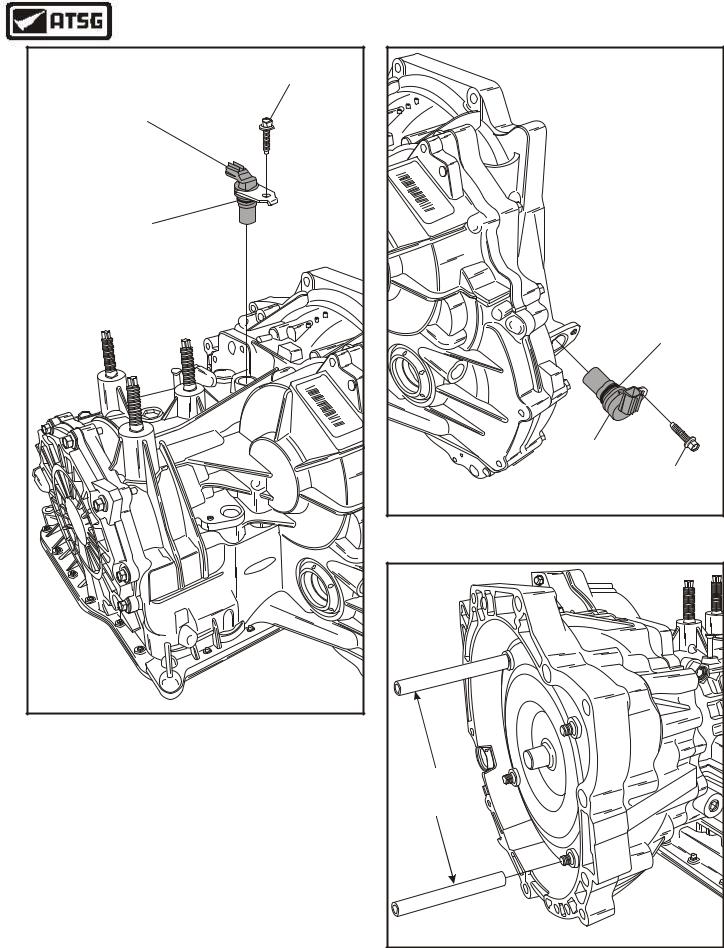
EXTERNAL COMPONENTS (Cont'd)
3.Remove the turbine shaft speed sensor from the case, as shown in Figure 16.
4.Remove the output speed sensor from the case, as shown in Figure 17.
5.Install the converter handles 307-091 onto the converter, as shown in Figure 18, that allows you to rotate the converter as you remove it.
Continued on Page 19.
|
P |
|
|
V |
|
X |
AA |
|
S |
||
4 |
|
|
P |
|
|
|
BF |
|
|
01 |
- |
|
9 |
|
|
3 |
XS4PBF |
|
4 |
|
|
2 |
|
|
0 |
|
|
|
7 |
|
|
6 |
|
|
9 |
|
|
REMOVE AND |
|
|
DISCARD "O" RING |
|
|
OUTPUT SHAFT |
|
|
SPEED SENSOR |
|
|
RETAINING |
|
|
BOLT |
|
|
Copyright © 2004 ATSG |
Figure 17
CONVERTER |
HANDLES |
307-091 |
Copyright © 2004 ATSG |
Figure 18
18 |
AUTOMATIC TRANSMISSION SERVICE GROUP |
|
Technical Service Information
EXTERNAL COMPONENTS (Cont'd)
Note: To avoid damaging the converter hub,
do not tilt the converter when removing it.
7.Install the Mounting Bracket 307-410 onto the transaxle, as shown in Figure 19, and install into a suitable bench mount that will allow you to rotate the transaxle.
INTERNAL COMPONENTS
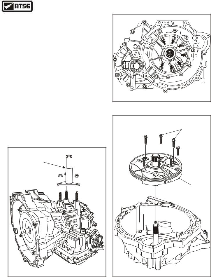
1.Remove the seven oil pump retaining bolts, as shown in Figure 20.
2.Remove the oil pump assembly using a slide hammer in the pump body holes.
3.Remove the oil pump assembly from transaxle, as shown in Figure 21, and set aside for the component rebuild section.
Continued on Page 20.
MOUNTING |
|
|
|
|
|
|
|
|
|
|
|
BRACKET |
|
|
|
|
|
|
|
|
|
|
|
307-410 |
|
|
|
|
|
|
|
|
|
|
|
|
|
|
|
|
|
|
- |
A |
B |
|
|
|
|
|
7F |
|
293 |
|
0 |
7 |
|
5 |
|
|
|
P - |
|
1 |
0 |
|
|
1 |
2 |
|
|
d |
S |
4 |
9 |
|
|
2 |
|
|
|
||
X |
9 |
|
|
V |
|
|
|
|
|||
r |
|
|
A |
|
|
|
|
|
|
||
o |
|
|
|
|
|
|
|
|
|
|
|
F |
|
|
|
|
|
|
|
|
|
|
|
Copyright © 2004 ATSG |
|||||||||||
Copyright © 2004 ATSG |
Figure 20
OIL PUMP BOLTS |
(7 REQUIRED) |
OIL PUMP |
ASSEMBLY |
Copyright © 2004 ATSG |
Figure 19 |
Figure 21 |
AUTOMATIC TRANSMISSION SERVICE GROUP |
19 |
|
Technical Service Information
INTERNAL COMPONENTS (CONT'D)
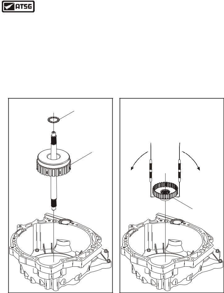
4.Remove the forward clutch housing assembly and the housing to oil pump thrust washer by pulling straight up, as shown in Figure 22.
Note: Thrust washer may stick to oil pump.
5.Set the forward clutch housing aside for the component rebuild section.
6.Remove the forward clutch hub from transaxle using two scribes as levers to dis-lodge the hub from the cir-clip, as shown in Figure 23.
Note: Cir-clip is located on front planetary sun gear and shaft shaft.
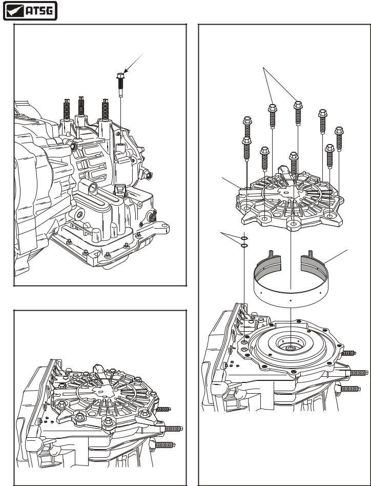
7.Remove the intermediate/overdrive band anchor bolt, as shown in Figure 24.
FORWARD CLUTCH |
THRUST WASHER |
FORWARD CLUTCH |
HOUSING ASSEMBLY |
Copyright © 2004 ATSG |
Figure 22
8.Rotate the transaxle so that the end cover is facing up, as shown in Figure 25.
9.Remove the nine end cover retaining bolts, as shown in Figure 26, and remove end cover.
10.Remove and discard the two end cover to case "O" ring seals, as shown in Figure 26.
11.Remove the intermediate/overdrive band, as shown in Figure 26.
Continued on Page 22
REMOVING FORWARD |
CLUTCH HUB |
FORWARD |
CLUTCH HUB |
Copyright © 2004 ATSG |
Figure 23
20 |
AUTOMATIC TRANSMISSION SERVICE GROUP |
|
Technical Service Information
INTERMEDIATE/OVERDRIVE |
BAND ANCHOR BOLT |
(SELECTIVE) |
Copyright © 2004 ATSG |
Figure 24
Copyright © 2004 ATSG |
|
10 |
111 |
|
112 |
|
|
107 |
10 |
END COVER RETAINING BOLTS (9 REQUIRED). |
107 |
INTERMEDIATE/OVERDRIVE BAND ASSEMBLY. |
111 |
END COVER ASSEMBLY. |
112 |
END COVER TO CASE "O" RING SEALS (2 REQUIRED). |
|
Copyright © 2004 ATSG |
Figure 25 |
Figure 26 |
AUTOMATIC TRANSMISSION SERVICE GROUP |
21 |
|