

4F27E
.pdfTechnical Service Information
21
19
20
19
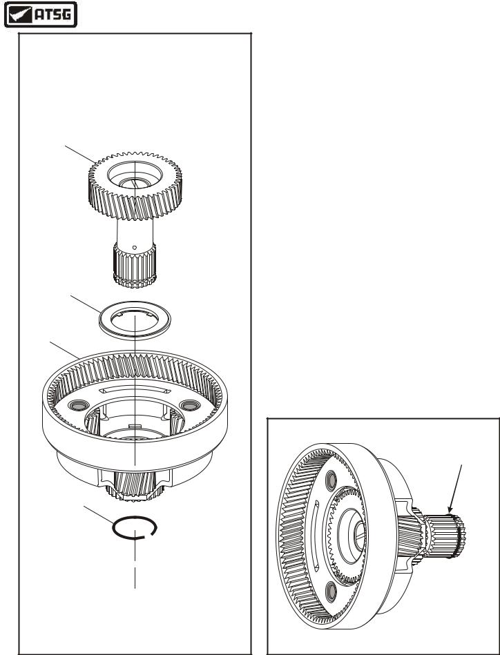
DO NOT REMOVE
THIS SNAP RING
18
18FRONT RING GEAR AND HUB ASSEMBLY (REAR VIEW).
19LOW SPRAG ASSEMBLY END BEARINGS (2 REQUIRED).
20LOW SPRAG CAGE ASSEMBLY.
Copyright © 2004 ATSG
Figure 91
COMPONENT REBUILD SECTION
PLANETARY ASSEMBLIES (CONT'D)
4.Position front ring gear and hub assembly on flat work surface, as shown in Figure 91.
Note: Notice in Figure 90 & Figure 91 that snap ring does not need to be removed.
5.Install low sprag end bearing in the direction shown in Figure 91, down against snap ring.
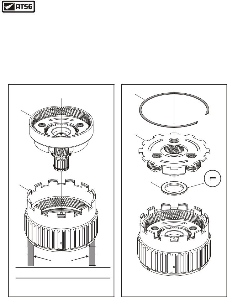
6.Install the low sprag into the ring gear with the flat side of the tabs facing up and the windows facing left, as shown in Figure 92.
7.Install the second low sprag end bearing into ring gear with flat side facing up, as shown in Figure 91.
8.Install the low sprag retainer onto the ring gear, as shown in Figure 91, by snapping onto the ring gear and ensure that it is fully seated, as shown in Figure 93.
Continued on Page 52
Tab With
Flat Side
Facing Up
Windows
Facing Left
Figure 92
completed ring gear hub assembly
Copyright © 2004 ATSG
Figure 93
52 |
AUTOMATIC TRANSMISSION SERVICE GROUP |
|
Technical Service Information
|
13 |
|
15 |
|
16 |
|
14 |
13 |
FRONT PLANETARY SUN GEAR. |
14 |
FRONT PLANETARY SUN GEAR SNAP RING (CIR-CLIP). |
15 |
FRONT PLANETARY CARRIER THRUST BEARING (NUMBER 6). |
16 |
FRONT PLANETARY CARRIER/REAR RING GEAR ASSEMBLY. |
|
Copyright © 2004 ATSG |
COMPONENT REBUILD SECTION
PLANETARY ASSEMBLIES (CONT'D)
9.Install the number 6 front planetary carrier thrust bearing into the front planetary carrier, as shown in Figure 94, with the internal tabs facing down and retain with Trans-Jel®.
10.Install the front planetary sun gear into front planetary carrier by rotating into position, as shown in Figure 94.
11.Now install the snap ring (Cir-Clip) into the groove in the sun gear shaft, as shown in Figure 95, and insure it is fully seated.
Note: This cir-clip is what retains the forward clutch hub and must be squeezed into the groove far enough to get the forward clutch hub installed during final assembly.
Continued on Page 54
Ensure That Cir-Clip |
Is Fully Seated |
Copyright © 2004 ATSG |
Figure 94 |
Figure 95 |
AUTOMATIC TRANSMISSION SERVICE GROUP |
53 |
|
Technical Service Information
COMPONENT REBUILD SECTION
PLANETARY ASSEMBLIES (CONT'D)
12.Place the pre-assembled ring gear and hub assembly on flat work surface with some type of spacers below ring gear to allow the shaft of the sun gear to protrude through ring gear. Refer to Figure 96.
13.Install the pre-assembled front planet and sun gear assembly into front ring gear by rotating into position, as shown in Figure 96, until fully seated
14.Install the number five, rear planetary carrier thrust bearing, onto the front sun gear in the direction shown in Figure 97, with the inside lip facing down.
15.Install the rear planetary carrier by rotating into position, as shown in Figure 97.
16.Install the rear planetary carrier retaining snap ring, as shown in Figure 97.
17.Set completed planetary gear assembly aside for the final assembly process (See Figure 98).
|
16 |
17 |
|
|
SPACERS |
16 |
FRONT PLANETARY CARRIER/REAR RING GEAR ASSEMBLY. |
17 |
FRONT PLANETARY CARRIER RING GEAR AND HUB ASSEMBLY. |
|
Copyright © 2004 ATSG |
Figure 96
|
10 |
|
11 |
|
12 |
10 |
REAR PLANETARY CARRIER RETAINING SNAP RING. |
11 |
REAR PLANETARY CARRIER ASSEMBLY. |
12 |
REAR PLANETARY/SUN GEAR THRUST BEARING (NUMBER 5). |
|
Copyright © 2004 ATSG |
Figure 97
54 |
AUTOMATIC TRANSMISSION SERVICE GROUP |
|

Technical Service Information
COMPLETED PLANETARY GEAR ASSEMBLY
Copyright © 2004 ATSG
Figure 98
COMPONENT REBUILD SECTION
MANUAL CONTROL LINKAGE
1.Inspect the internal control detent lever and bracket assembly for any wear and/or damage, as shown in Figure 99.
2.Inspect the detent spring for any wear and/or damage (See Figure 99).
3.Install new "O" ring seals on the manual shaft, as shown in Figure100, and lubricate seals with small amount of Trans-Jel®.
4.Set both parts aside for final assembly process.
INTERNAL CONTROL DETENT |
|
|
LEVER AND BRACKET ASSEMBLY |
|
|
|
"O" RING |
|
DETENT SPRING |
SEALS |
|
|
||
PARKING PAWL |
MANUAL CONTROL SHAFT |
|
ACTUATING ROD |
||
|
||
|
"O" RING SEALS |
|
|
INSTALLED |
|
Copyright © 2004 ATSG |
Copyright © 2004 ATSG |
Figure 99 |
Figure 100 |
AUTOMATIC TRANSMISSION SERVICE GROUP |
55 |
|
Technical Service Information
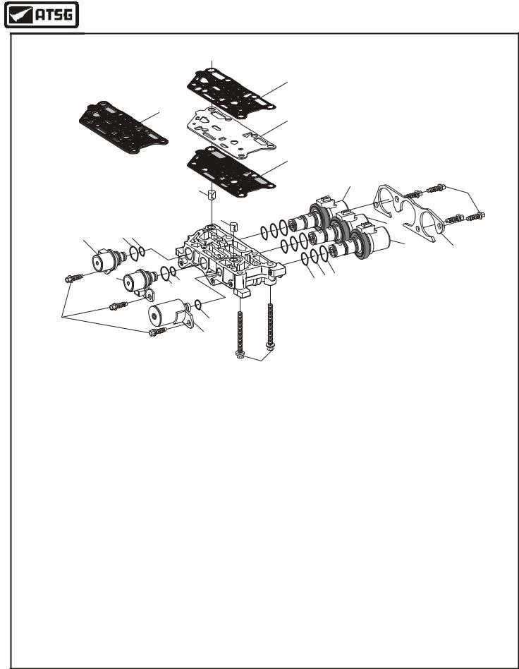
SOLENOID BODY EXPLODED VIEW
11
12
10


 9 (SOME MODELS)


15
8 |
7 |
8
14
1 |
2 |
3 |
13
16
4 |
2 3 |
19 |
18 17 |
|
|
||
|
|
|
7
6
Upper and Lower Valve Bodies
5
Found on Page 57
20
1SHIFT SOLENOID "B"
2SHIFT SOLENOID "A" AND "B" LARGE "O" RING SEAL
3SHIFT SOLENOID "A" AND "B" SMALL "O" RING SEAL
4SHIFT SOLENOID "A"
5ELECTRONIC PRESSURE CONTROL (EPC) SOLENOID
6EPC SOLENOID "O" RING SEAL
7SOLENOID RETAINING BOLTS (7 REQUIRED)
8SOLENOID BODY TO LOWER V. B. ALIGNMENT DOWELS (2 REQ)
9SOLENOID BODY TO SPACER PLATE GASKET, WITH SCREENS
10SOLENOID BODY SPACER PLATE
11SOLENOID BODY SPACER PLATE TO LOWER V. B. GASKET
12SPACER PLATE WITH MOLDED GASKETS (SOME MODELS)
13PWM SHIFT SOLENOID "C"
14PWM SHIFT SOLENOID "E"
15PWM SHIFT SOLENOID "D"
16PWM SHIFT SOLENOID RETAINING PLATE
17PWM SHIFT SOLENOID LARGE "O" RING SEAL (3 REQUIRED)
18PWM SHIFT SOLENOID MEDIUM "O" RING SEAL (3 REQUIRED)
19PWM SHIFT SOLENOID SMALL "O" RING SEAL (3 REQUIRED)
20SOLENOID BODY TO CASE BOLTS, 71mm LENGTH (2 REQUIRED)
21MANUAL SHIFT VALVE
22SOLENOID BODY RETAINING BOLTS, 59MM LENGTH (5 REQUIRED)
23UPPER VALVE BODY CASTING
24VALVE BODY TO CASE SEALS (2 REQUIRED)
25UPPER V. B. TO LOWER V. B. BOLTS, 32MM LENGTH (5 REQUIRED)
26UPPER V. B. TO LOWER V. B. BOLTS, 40MM LENGTH (9 REQUIRED)
27LOW/REVERSE SHIFT VALVE
28LOW/REVERSE SHIFT VALVE SPRING
29VALVE LINE-UP RETAINER (7 REQUIRED)
30SOLENOID PRESSURE REGULATOR VALVE SPRING
31SOLENOID PRESSURE REGULATOR VALVE
32UPPER VALVE BODY TO SPACER PLATE GASKET
33VALVE BODY SPACER PLATE
34LOWER VALVE BODY TO SPACER PLATE GASKET
35TORQUE CONVERTER RELIEF VALVE SPRING
36TORQUE CONVERTER RELIEF VALVE
37TORQUE CONVERTER CLUTCH CONTROL VALVE SPRING
38TORQUE CONVERTER CLUTCH CONTROL VALVE
39CLUTCH CONTROL VALVE SPRING
40CLUTCH CONTROL VALVE
413-4 SHIFT VALVE SPRING
423-4 SHIFT VALVE
43SHIFT SOLENOID "C" ACCUMULATOR SPRING
44SHIFT SOLENOID "C" ACCUMULATOR PISTON
45SOLENOID SHIFT VALVE
46SOLENOID SHIFT VALVE SPRING
47MAIN PRESSURE REGULATOR VALVE
48MAIN PRESSURE REGULATOR VALVE SPRING
49MAIN PRESSURE REGULATOR VALVE BORE PLUG
50MAIN PRESSURE REGULATOR VALVE BORE PLUG RETAINER
51LOWER V. B. TO UPPER V. B. ALIGNMENT DOWELS (2 REQUIRED)
52LOWER VALVE BODY CASTING
Copyright © 2004 ATSG
Figure 101
56 |
AUTOMATIC TRANSMISSION SERVICE GROUP |
|
Technical Service Information
|
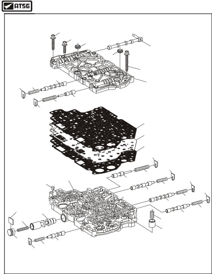
UPPER AND LOWER VALVE BODY EXPLODED VIEW |
|
|
|
26 |
|
|
|
25 |
|
|
|
24 |
|
|
|
|
21 |
|
|
|
24 |
|
|
|
22 |
|
|
27 |
23 |
|
|
28 |
|
|
29 |
|
|
|
|
31 |
|
|
|
30 |
|
|
|
29 |
|
|
|
|
32 |
|
|
|
33 |
|
|
|
34 |
|
|
|
29 |
|
|
|
|
29 |
|
|
35 |
|
|
52 |
36 |
29 |
|
51 |
|
|
|
|
37 |
|
|
|
|
|
|
|
38 |
29 |
|
|
51 |
39 |
|
|
|
|
|
|
|
40 |
50 |
47 |
|
41 |
|
42 |
||
|
|
||
|
|
|
|
48 |
|
|
43 |
|
|
|
44 |
49 |
45 |
|
|
|
|
|
|
|
46 |
|
|
|
29 |
|
|
|
Solenoid Body and |
|
|
|
Legend Found on Page 56 |
|
|
|
|
|
Copyright © 2004 ATSG |
Figure 102
AUTOMATIC TRANSMISSION SERVICE GROUP |
57 |
|
Technical Service Information
COMPONENT REBUILD SECTION
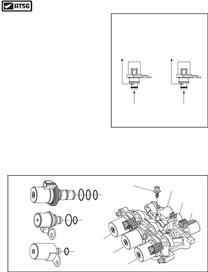
SOLENOID BODY
1.Disassemble complete solenoid body assembly using Figure 101 as a guide.
2.Clean all solenoid body parts thoroughly and dry with compressed air.
3.Inspect all solenoid body parts thoroughly for any wear and/or damage.
4.There are three different styles of solenoids in this solenoid body. The locations and styles are identified in Figure 104, along with their OEM part numbers.
5.Mechanically check shift solenoids "A" & "B", as shown in Figure 103, which have had some concerns.
6.Install new "O" rings on each of the solenoids, as shown in Figure 104, and lubricate with a very small amount of Trans-Jel®.
7.Install the solenoids in their proper positions, as shown in Figure 104, and install retaining brackets and bolts. (See Figure 101).
8.Torque the solenoid retaining bolts to
9 N•m (80 in.lb.).
9.Install the ground terminal retaining bolt for shift solenoids "C", "D" and "E", finger tight at this time (See Figure 104).
10.Set the completed solenoid body aside for the valve body sub assembly.
SHIFT SOLENOID "A" & "B"
MECHANICAL CHECK
SOLENOID OFF |
SOLENOID ON |
SHIFT VALVE
TO SHIFT
PRESSURE
VALVE
EXHAUSTED
PRESSURE FROM SOLENOID |
PRESSURE FROM SOLENOID |
REGULATOR VALVE BLOCKED |
REGULATOR VALVE CONNECTED |
|
TO THE SHIFT VALVE |
Copyright © 2004 ATSG
Figure 103
|
GROUND |
SHIFT |
|
TERMINAL |
|
SHIFT |
BOLT |
SOLENOID "B" |
|
|
|
SOLENOID |
|
SHIFT |
"C" "D" & "E" |
|
|
|
SOLENOID "A" |
|
XS4Z-7G484-AA |
|
|
|
EPC |
|
|
|
|
|
L |
SOLENOID |
|
|
B |
SHIFT |
|
|
SOLENOID |
|
N |
|
G |
|
"A" & "B" |
|
|
|
|
|
XS4Z-7H148-AA |
|
B |
|
SHIFT |
N |
|
|
|
|
SOLENOID "D" |
|
EPC |
SHIFT |
|
SOLENOID |
|
|
SOLENOID "E" |
|
|
XS4Z-7G383-AA |
|
|
|
SHIFT |
|
|
SOLENOID "C" |
Copyright © 2004 ATSG |
|
|
Figure 104
58 |
AUTOMATIC TRANSMISSION SERVICE GROUP |
|
Technical Service Information
COMPONENT REBUILD SECTION
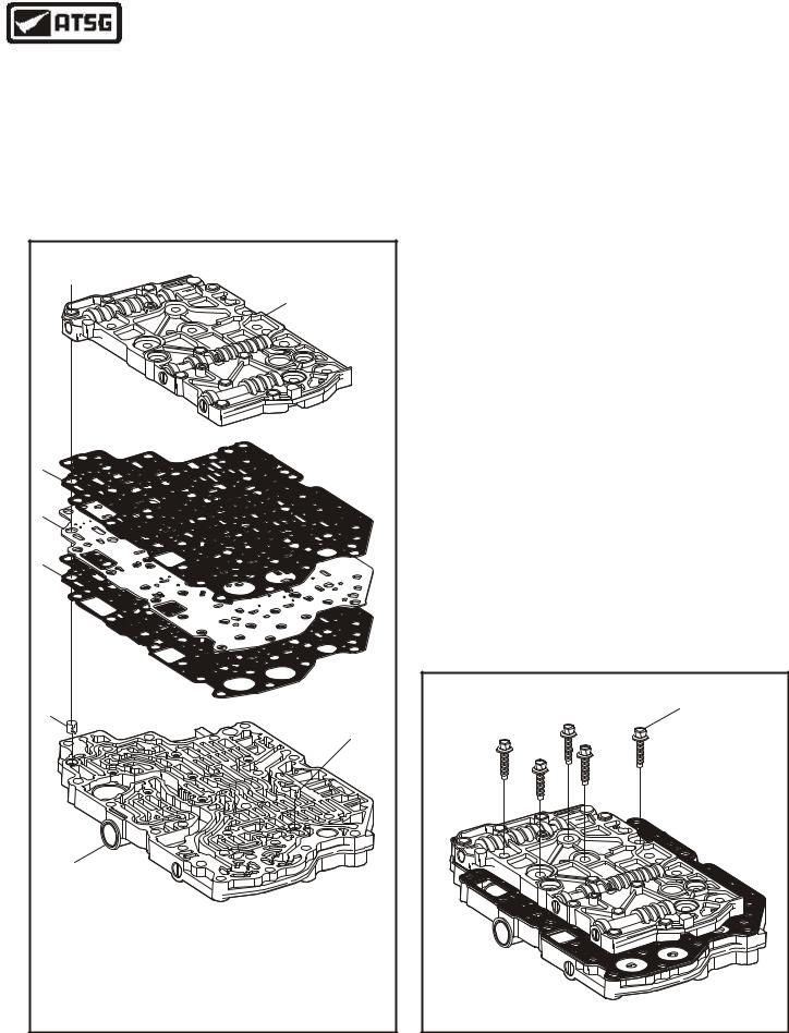
UPPER AND LOWER VALVE BODIES
1.Disassemble the upper and lower valve bodies using Figure 102 as a guide.
2.Lay each valve line-up out in order as you remove them from the valve body casting.
3.Inspect each valve, valve spring, bore plug and retainer for any wear and/or damage.
|
6 |
5 |
|
4 |
|
3 |
|
1 |
|
|
1 |
|
2 |
1 |
LOWER VALVE BODY ALIGNMENT DOWELS (2 REQUIRED). |
2 |
COMPLETED LOWER VALVE BODY. |
3 |
LOWER VALVE BODY TO SPACER PLATE GASKET. |
4 |
VALVE BODY SPACER PLATE. |
5 |
SPACER PLATE TO UPPER VALVE BODY GASKET. |
6 |
COMPLETED UPPER VALVE BODY. |
|
Copyright © 2004 ATSG |
4.Clean all upper and lower valve body parts thoroughly and dry with compressed air.
5.Install each valve train back into their bores exactly as shown in Figure 102, lubricating them with Mercon® V as they are installed.
6.Extra care here will eliminate some of the troublesome problems encountered later.
7.Lay the completed lower valve body on a flat work surface, as shown in Figure 105.
8.Install the two valve body dowels, as shown in Figure 105, if you have not already done so.
9.Install the lower valve body to spacer plate gasket over dowels and onto lower valve body, as shown in Figure 105.
10.Install the valve body spacer plate over dowels onto lower valve body, as shown in Figure 105.
11.Install spacer plate to upper valve body gasket over dowels onto spacer plate (See Figure 105).
Note: Later models have the upper gasket molded to the spacer plate.
12.Install the completed upper valve body over dowels and onto the upper gasket, as shown in Figure 105.
13.Install 5 valve body bolts 32 mm length, in the positions shown in Figure 106, and just finger tighten at this time.
Continued on Page 60
VALVE BODY BOLTS |
32 MM LENGTH |
(5 REQUIRED) |
Copyright © 2004 ATSG |
Figure 105 |
Figure 106 |
AUTOMATIC TRANSMISSION SERVICE GROUP |
59 |
|
Technical Service Information
VALVE BODY BOLTS |
40 MM LENGTH |
(9 REQUIRED) |
Copyright © 2004 ATSG |
Figure 107
COMPONENT REBUILD SECTION
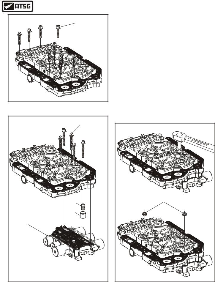
UPPER AND LOWER VALVE BODIES (CONT'D)
14.Install 9 valve body bolts 40 mm length, in the positions shown in Figure 107, and just finger tighten at this time.
15.Install shift solenoid "C" accumulator spring and piston into lower valve body, as shown in Figure 108.
16.Place the completed solenoid body with gasket into the lower valve body dowel pin holes, as shown in Figure 108.
17.Install 5 solenoid body bolts 59 mm length, in the positions shown in Figure 108, and finger tighten at this time.
18.Now you can torque all valve body bolts to,
9 N•m (80 in.lb.), as shown in Figure 109, and install two new valve body to case seals.
19.Set the completed valve body assembly aside for the final assembly process.
VALVE BODY BOLTS |
59 MM LENGTH |
(5 REQUIRED) |
43 |
44 |
COMPLETED |
SOLENOID BODY |
43 SHIFT SOLENOID "C" ACCUMULATOR SPRING. |
44 SHIFT SOLENOID "C" ACCUMULATOR PISTON. |
Copyright © 2004 ATSG |
VALVE BODY TO |
CASE SEALS (2) |
Copyright © 2004 ATSG |
Figure 108 |
Figure 109 |
60 |
AUTOMATIC TRANSMISSION SERVICE GROUP |
|
Technical Service Information
COMPONENT REBUILD SECTION
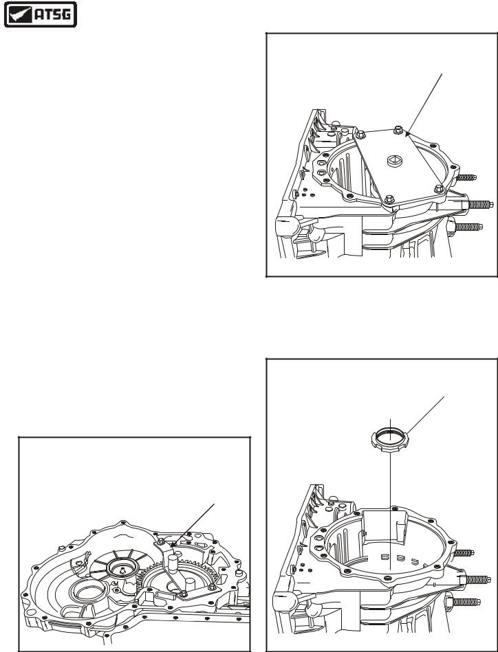
BEARING REPLACEMENT AND SET-UP
1.Rotate transaxle case in the fixture, as shown in Figure 110.
2.Secure the final drive input gear assembly, by installing the final drive input gear holding tool 307-413, as shown in Figure 110.
Note: The transaxle will be rotated several times to remove the bearing retainer nut. To prevent the final drive input gear from falling out, it "Must" be secured.
3.Lock the final drive input gear into position using the pins on the tool that go into holes in the input gear (See Figure 110).
4.Rotate the transaxle 180 degrees so that end cover side is facing up (See Figure 111).
Note: The two staked areas on the nut must be pushed away from the flats on the final drive input gear before the bearing retainer nut can be removed.
REMOVAL TOOL |
307-414 |
Copyright © 2004 ATSG |
5. Install the final drive input nut socket 307-414 |
Figure 111 |
and wrenching plate, as shown in Figure 111. |
|
6. Loosen the retainer nut with the tools. |
|
7. Remove the special tools and remove the final |
|
drive input gear retaining nut, as shown in |
|
Figure 112. |
|
Continued on Page 62
HOLDING TOOL |
307-413 |
Copyright © 2004 ATSG |
Figure 110
FINAL DRIVE INPUT |
GEAR RETAINING NUT |
Copyright © 2004 ATSG |
Figure 112
AUTOMATIC TRANSMISSION SERVICE GROUP |
61 |
|