

4F27E
.pdfFORD MOTOR CO .
4F27E TRANSAXLE
GOTO PAGE
INDEX
PREVIOUS MENU
IDENTIFICATION TAG LOCATION AND INFORMATION ................................................................... |
3 |
GENERAL DESCRIPTION ......................................................................................................................... |
4 |
TRANSAXLE INTERNAL COMPONENT APPLICATION CHART ........................................................ |
5 |
SHIFT SOLENOID APPLICATION CHART AND IDENTIFICATION .................................................. |
6 |
TRANSAXLE INTERNAL COMPONENT RESISTANCE CHART .......................................................... |
7 |
ELECTRICAL COMPONENT WIRE SCHEMATIC ................................................................................. |
8 |
GEAR RATIO IDENTIFICATION .............................................................................................................. |
9 |
ELECTRONIC COMPONENT DESCRIPTION ......................................................................................... |
9 |
FAIL-SAFE OPERATION ............................................................................................................................ |
9 |
PCM LOCATION AND PIN IDENTIFICATION ....................................................................................... |
10 |
TRANSAXLE RANGE SENSOR WIRE SCHEMATIC .............................................................................. |
12 |
DIAGNOSTIC TROUBLE CODE CHARTS ............................................................................................... |
15 |
LINE PRESSURE TEST .............................................................................................................................. |
16 |
TRANSAXLE DISASSEMBLY .................................................................................................................... |
17 |
COMPONENT REBUILD SECTION |
|
OIL PUMPASSEMBLY .......................................................................................................................... |
31 |
FORWARD CLUTCH HOUSING ASSEMBLY ..................................................................................... |
37 |
REAR END COVER ................................................................................................................................ |
40 |
DIRECT/REVERSE HOUSING DISASSEMBLE ................................................................................. |
42 |
DIRECT CLUTCH HOUSING ASSEMBLY .......................................................................................... |
43 |
REVERSE CLUTCH HOUSING ASSEMBLY ....................................................................................... |
45 |
PLANETARY GEAR ASSEMBLIES ...................................................................................................... |
50 |
MANUAL CONTROL LINKAGE ........................................................................................................... |
55 |
SOLENOID BODYASSEMBLY ............................................................................................................. |
58 |
UPPER AND LOWER VALVE BODYASSEMBLIES .......................................................................... |
59 |
BEARING REPLACEMENT AND GEAR SET-UP .............................................................................. |
61 |
TRANSAXLE ASSEMBLY ........................................................................................................................... |
75 |
INTERMEDIATE/OVERDRIVE BAND ADJUSTMENT .......................................................................... |
86 |
BOLT IDENTIFICATION CHART ............................................................................................................. |
92 |
TORQUE SPECIFICATIONS AND FLUID REQUIREMENTS ............................................................... |
93 |
SPECIAL TOOL REQUIREMENTS AND LIST ........................................................................................ |
94 |
EXPLODED TRANSAXLE VIEWS ............................................................................................................. |
100 |
AIR PRESSURE CHECKS ........................................................................................................................... |
111 |
AUTOMATIC TRANSMISSION SERVICE GROUP
9200 S. DADELAND BLVD. SUITE 720
MIAMI, FLORIDA 33156
(305) 670-4161
Copyright © ATSG 2004
2
Technical Service Information
|
|
|
|
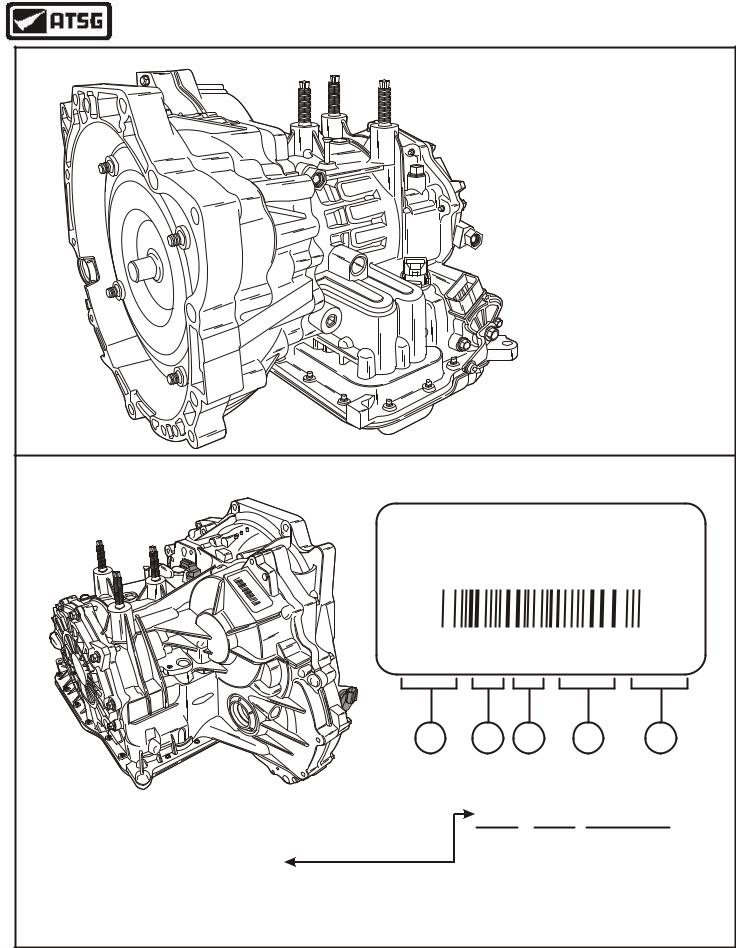
FORD 4F27E |
4 = 4 Forward Speeds |
|
||
|
|
|
|
|
|
|||
|
|
|
|
|
F = Front Wheel Drive |
|
||
|
|
|
|
|
72 } = Relative Torque Capacity |
|||
|
|
|
|
|
E = Electronic Controlled |
|||
I.D. TAG INFORMATION FOUND ON RIGHT SIDE OF TRANSMISSION CASE |
||||||||
|
|
|
|
PVAA XS4P-DA |
||||
|
|
|
P |
|
|
|
|
|
|
|
|
V |
|
|
|
|
|
|
X |
|
AA |
|
|
|
|
|
|
SP |
|
|
|
|
|
|
|
|
4 |
|
X |
|
|
|
|
|
|
|
BF |
|
|
|
|
||
|
|
|
S |
|
|
|
|
|
|
|
0 |
4 |
|
|
|
|
|
|
|
|
1 |
P |
|
|
|
|
|
|
|
9 |
- |
|
|
|
|
|
|
|
3 |
B |
|
|
|
|
|
|
|
42 |
F |
|
|
|
|
|
|
|
06 |
|
|
|
|
|
|
|
|
7 |
|
|
|
|
|
|
|
|
9 |
|
|
|
|
|
|
|
|
|
XS4P DA 01 9342 0769 |
||||
ord |
|
|
|
|
|
|
|
|
F |
|
|
|
|
|
|
|
|
|
|
|
|
1 |
2 |
3 |
4 |
5 |
1. Part Number, Basic = 7000 |
(Example XS4Z-7000-DA) |
|
Year |
Julian Date |
||||
BD- |
9 |
342 |
|
|||||
2. Transmission Model Code |
|
|
|
|
|
|||
|
|
|
|
Build |
9=1999 |
|
|
|
3. Engineering Level |
|
|
|
|
|
|
||
4. Build Date (Year and Julian Date) |
Date |
0=2000 |
|
|
||||
|
1=2001 |
|
|
|||||
5. Serial Number |
|
|
|
|
|
|
|
|
|
|
|
|
|
2=2002 |
|
|
|
|
|
|
|
|
|
3=2003 |
|
|
|
|
|
|
|
|
4=2004 |
|
|
|
|
|
|
|
|
Copyright © 2004 ATSG |
||
Figure 1
AUTOMATIC TRANSMISSION SERVICE GROUP |
3 |
|
Technical Service Information
GENERAL DESCRIPTION
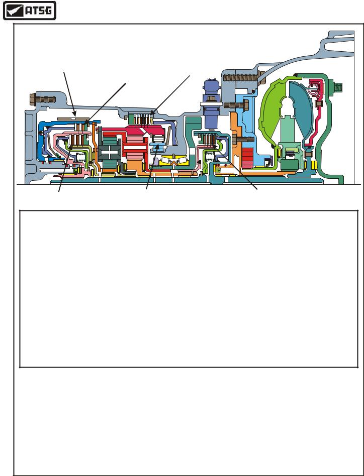
This is a four speed, Front Wheel Drive, with fully electronic controls for the upshifts and downshifts, with 4th gear being overdrive. The individual gear ratios are achieved through two planetary gear sets connected one behind the other. The components of the planetary gear sets are driven or locked by means of four multiple plate clutches, one brake band and a one-way roller clutch, and are illustrated in Figure 3, along with the component application chart for each gear. To minimize fuel consumption, the torque converter clutch is applied by the PCM in 3rd and 4th gears, depending on throttle position and vehicle speed. This unit is designed to use Mercon® V automatic transmission fluid.
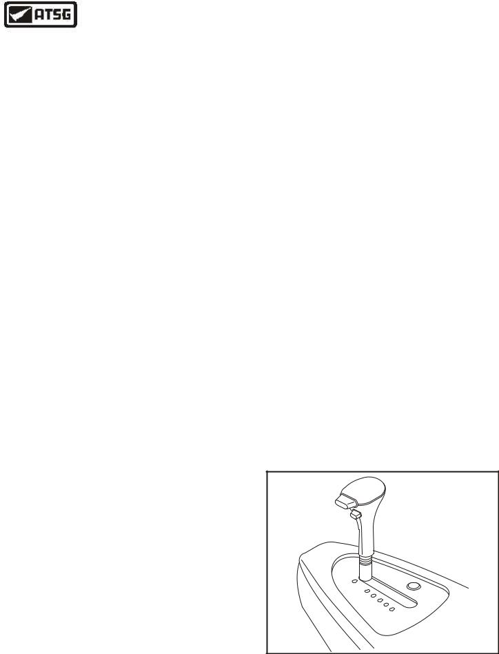
The manual selector lever, shown in Figure 2, gives the driver a choice of "P", "R", "N", "D", "2", "1", and all ranges are explained in detail below. It is also possible to operate an O/D cancel switch, located on the selector lever, to prevent the transaxle from shifting into 4th gear or to shift down to 3rd gear.
Special Note: This transaxle currently shows two different axle ratios and Page 9 also shows how to identify which ratio belongs in the vehicle that you may have. Surely you must know by now that the PCM will recogonize almost instantly if you install the wrong axle ratio.
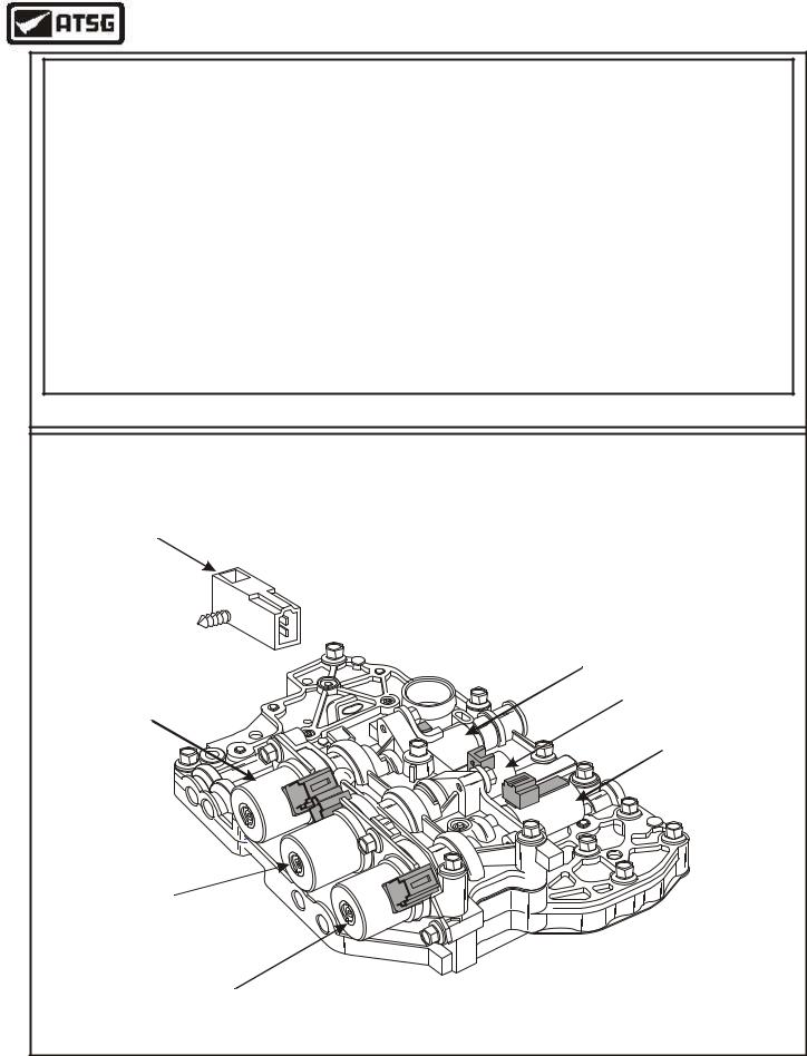
The 4F27E transaxle is equipped with six different solenoids to shift the transaxle through the various gears and to control line pressure. Shift Solenoids "A" and "B" are On-Off solenoids and control shift valves in the valve body. Shift Solenoids "C", "D" and "E" are Pulse Width Modulated (PWM) solenoids and control the pressures to the various apply components. The sixth solenoid is the Electronic Pressure Control (EPC) solenoid. Refer to Figure 4 for the solenoid application chart for each gear and for the location and identification of each solenoid on the valve body.
MANUAL SELECTOR LEVER OPERATION
P In manual selector lever position "P" no gear is selected. The parking pawl is engaged manually by the shift shaft linkage and the engine can be started.
RIn manual selector lever position "R" reverse gear is selected. Reverse allows the vehicle to be operated in a rearward direction, at a reduced gear ratio.
N In manual selector lever position "N" no gear is selected. The driveline is not locked, so the wheels are free to rotate. The engine may be started in Neutral.
D In manual selector lever position "D" the transmission control system allows upshifts first through fourth gears automatically. When the O/D cancel switch is pressed, shifting into 4th gear is prevented, or if it is already in 4th gear, the transmission shifts down to 3rd gear.
2In manual selector lever position "2" only 2nd gear is available. The transmission controls will not allow a shift into first gear.
If the manual selector lever is moved to position "2" at an excessive vehicle speed for 2nd gear, the computer only allows the shift to take place when a safe vehicle speed has been reached.
1In manual selector lever position "1" only first is available.. The transmission control system applies the Low/Reverse clutch to provide engine braking effect.
If the manual selector lever is moved to position "1" at an excessive vehicle speed for 1st gear, the computer only allows the down shift to take place when a safe vehicle speed has been reached.
P
R N D 2 1
Copyright © 2004 ATSG
Figure 2
4 |
AUTOMATIC TRANSMISSION SERVICE GROUP |
|
Technical Service Information
2nd/4th |
|
Low/Reverse |
|
Band |
Reverse |
||
Clutch |
|||
|
Clutch |
|
|
Direct Clutch |
Low One-Way |
Forward Clutch |
|
|
Clutch |
|
4F27E TRANSAXLE COMPONENT APPLICATION CHART
|
Forward |
2nd-4th |
Direct |
Reverse |
Low/Rev |
Low One-Way |
Gear |
RANGE |
Clutch |
Band |
Clutch |
Clutch |
Clutch |
Clutch |
Ratio |
|
|
|
|
|
|
|
|
PARK |
|
|
|
|
|
|
|
REVERSE |
|
|
|
ON |
ON |
|
2.65 |
NEUTRAL |
|
|
|
|
|
|
|
DRIVE-1st |
ON |
|
|
|
|
HOLD |
2.82 |
DRIVE-2nd |
ON |
ON |
|
|
|
|
1.50 |
DRIVE-3rd |
ON |
|
ON |
|
|
|
1.00 |
DRIVE-4th |
|
ON |
ON |
|
|
|
0.73 |
MANUAL-2nd |
ON |
ON |
|
|
|
|
1.50 |
MANUAL-1st |
ON |
|
|
|
ON |
|
2.82 |
NOTE: Failsafe on this unit is 3rd gear in all forward ranges
NOTE: There are two different axle ratios listed for Ford Focus with this transaxle; NN = 3.693 Automatic
WW = 3.904 Automatic
REFER TO DOOR TAG INFORMATION ON PAGE 9
TO DETERMINE GEAR RATIO FOR YOUR VEHICLE.
Copyright © 2004 ATSG
Figure 3
AUTOMATIC TRANSMISSION SERVICE GROUP |
5 |
|
Technical Service Information
SHIFT SOLENOID APPLY CHART
|
Shift "A" |
Shift "B" |
Shift "C" |
Shift "D" |
Shift "E" |
EPC |
Range |
(On-Off) |
(On-Off) |
(PWM) |
(PWM) |
(PWM) |
Solenoid |
Park |
ON |
OFF |
Not Fed |
Not Fed |
Not Fed |
*** |
Reverse |
ON |
ON |
Not Fed |
OFF |
Not Fed |
*** |
Neutral |
ON |
OFF |
Not Fed |
Not Fed |
Not Fed |
*** |
Drive-1st |
OFF |
OFF |
OFF |
ON |
ON |
*** |
Drive-2nd |
OFF |
OFF |
OFF |
OFF |
ON |
*** |
Drive-3rd |
OFF |
OFF ** |
OFF ** |
OFF |
OFF |
*** |
Drive-4th |
ON |
OFF ** |
ON |
OFF |
OFF |
*** |
Manual-1st |
ON |
ON |
OFF |
OFF |
ON |
*** |
*** EPC Control dependent on throttle position and vehicle speed.
** TCC control dependent on throttle position, vehicle speed, brake switch.
SOLENOID AND FLUID TEMPERATURE SENSOR LOCATIONS
Transmission Fluid
Temp Sensor
(Snaps Onto Filter)
Shift Solenoid "D"
XS4Z-7G484-AA
Shift Solenoid "E"
XS4Z-7G484-AA
Shift Solenoid "B"
XS4Z-7H148-AA
ord F
L
B

N
G
B
N
Shift Solenoid "A"
XS4Z-7H148-AA
 EPC Solenoid
XS4Z-7G383-AA
Shift Solenoid "C"
XS4Z-7G484-AA
Copyright © 2004 ATSG
Figure 4
6 |
AUTOMATIC TRANSMISSION SERVICE GROUP |
|
Technical Service Information
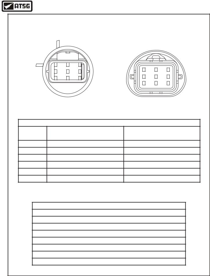
SOLENOID AND TRANSAXLE FLUID TEMP RESISTANCE CHART |
||||||
|
1 |
2 |
3 |
|
|
|
|
4 |
5 |
6 |
3 |
2 |
1 |
|
|
|
|
|||
|
7 |
8 |
9 |
6 |
5 |
4 |
|
|
|
|
|||
|
|
|
|
9 |
8 |
7 |
Transaxle Case Connector |
Vehicle Harness Connector |
|||||
|
(Face View) |
|
(Face View) |
|||
INTERNAL TRANSAXLE COMPONENTS RESISTANCE CHART |
||||||
Terminals |
|
|
Transaxle |
Ohms Resistance At |
||
|
|
Component |
|
20°C (70°F) |
||
|
|
|
|
|||
6 and Gnd. |
Shift Solenoid "A" (On-Off) |
|
10.9 - 26.2 |
|||
8 and Gnd. |
Shift Solenoid "B" (On-Off) |
|
10.9 - 26.2 |
|||
3 and Gnd. |
|
Shift Solenoid "C" (PWM) |
|
1.0 - 4.2 |
||
9 and Gnd. |
|
Shift Solenoid "D" (PWM) |
|
1.0 - 4.2 |
||
1 and Gnd. |
|
Shift Solenoid "E" (PWM) |
|
1.0 - 4.2 |
||
2 and 7 |
|
EPC Solenoid (PWM) |
|
2.4 - 7.3 |
||
|
|
NOTE: Gnd. = Ground Ohm Meter to the Case |
|
|||
|
Transaxle Temperature Sensor Resistance Chart Terminals 4 and 5 |
|||||
|
|
|
0°C (32°F) = 83.2k - 107k Ohms |
|
|
|
|
|
|
20°C (70°F) = 33.5k - 41.2k Ohms |
|
|
|
|
|
|
40°C (104°F) = 14.6k - 17.6k Ohms |
|
|
|
|
|
|
60°C (140°F) = 7.08k - 8.01k Ohms |
|
|
|
|
|
|
80°C (176°F) = 3.61k - 4.06k Ohms |
|
|
|
|
|
|
100°C (212°F) = 1.96k - 2.20k Ohms |
|
|
|
|
|
|
120°C (248°F) = 1.13k - 1.25k Ohms |
|
|
|
|
|
|
130°C (266°F) = 0.87k - 0.96k Ohms |
|
|
|
|
|
|
|
|
|
Copyright © 2004 ATSG |
Figure 5
AUTOMATIC TRANSMISSION SERVICE GROUP |
7 |
|
Technical Service Information
|
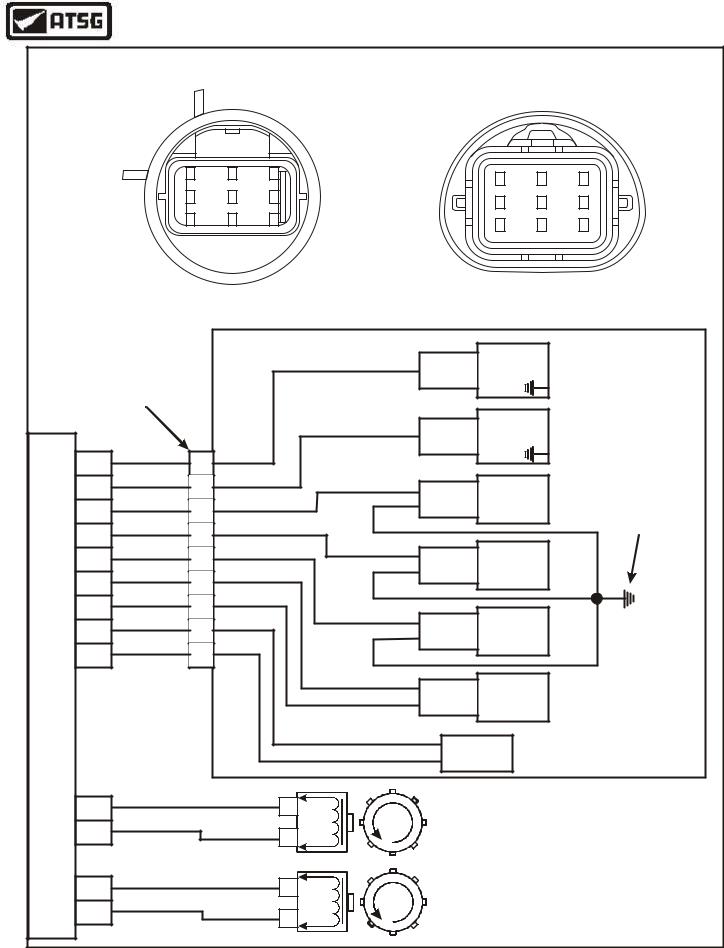
TRANSAXLE ELECTRICAL COMPONENT WIRE SCHEMATIC |
|||||||||
|
1 |
2 |
3 |
|
|
|
|
3 |
2 |
1 |
|
|
|
|
|
|
|
|
|||
|
4 |
5 |
6 |
|
|
|
|
6 |
5 |
4 |
|
|
|
|
|
|
|
|
|||
|
7 |
8 |
9 |
|
|
|
|
9 |
8 |
7 |
|
|
|
|
|
|
|
|
|||
|
Transaxle Case Connector |
|
|
Vehicle Harness Connector |
||||||
|
|
|
|
(Face View) |
||||||
|
(Face View) |
|
|
|
|
|
||||
|
|
|
|
|
|
|
|
|
||
|
|
|
|
|
|
"Natural" |
Shift |
|
|
|
|
|
|
|
|
White |
Solenoid "A" |
|
|||
Transaxle Case |
|
|
|
Harness |
(On-Off) |
|
|
|||
|
|
|
|
|
|
|||||
|
|
|
|
Connector |
|
|
|
|||
|
Connector |
|
|
|
|
|
|
|
|
|
|
|
|
|
|
|
"Black" |
Shift |
|
|
|
|
|
|
|
|
Purple |
Solenoid "B" |
|
|||
|
|
|
|
|
Harness |
|
||||
|
|
|
|
|
|
(On-Off) |
|
|
||
|
|
|
|
|
|
Connector |
|
|
||
73 |
Green/Yellow |
White |
|
|
|
|
|
|
||
|
|
|
|
|
|
|
|
|||
|
6 |
|
|
|
|
|
|
|
|
|
PCM |
Green/Blue |
Purple |
|
|
|
|
|
|
|
|
1 |
|
|
Green |
"White" |
Shift |
|
|
|||
|
8 |
|
|
|
Common External Ground |
|||||
82 |
Green/Black |
Green |
|
|
Blue |
Harness |
Solenoid "C" |
|||
|
|
(PWM) |
|
With Terminal On Valve |
||||||
|
3 |
|
|
|
Connector |
|
||||
99 |
Green/Orange |
Green |
|
|
|
|
|
|
|
Body Bolt |
|
9 |
|
|
Green |
|
|
|
|
|
|
102 |
Green/White |
Black |
|
|
"Blue" |
Shift |
|
|
||
Green/Orange |
1 |
|
|
Brown |
Harness |
Solenoid "D" |
|
|||
44 |
Blue |
|
|
|
Connector |
(PWM) |
|
|
||
|
2 |
|
|
|
|
|
|
|
|
|
81 |
Black/Red |
Orange |
|
|
|
|
|
|
|
|
|
7 |
|
|
Black |
"Green" |
Shift |
|
|
||
91 |
Brown |
Yellow |
|
|
|
|
||||
|
|
Blue |
Harness |
Solenoid "E" |
|
|||||
|
4 |
|
|
|
||||||
37 |
White/Green |
Yellow |
|
|
|
Connector |
(PWM) |
|
|
|
|
5 |
|
|
|
|
|
|
|
|
|
|
|
|
|
|
Blue |
"Black" |
EPC |
|
|
|
|
|
|
|
|
Orange |
Harness |
Solenoid |
|
|
|
|
|
|
|
|
|
Connector |
(PWM) |
|
|
|
|
|
|
|
(Signal Return) |
Yellow |
Transmission |
|
|
||
|
|
|
|
|
Yellow |
|
|
|||
|
|
|
|
|
Fluid Temp |
|
|
|||
|
|
|
|
|
|
|
|
|
||
58 |
White/Blue |
|
|
1 Output |
|
|
|
|
|
|
|
|
|
|
|
|
|
|
|
||
33 |
Brown/Blue |
(Signal Return) |
Speed |
|
|
|
|
|
|
|
|
2 Sensor |
|
|
|
|
|
|
|||
PCM |
|
|
|
|
|
|
|
|
|
|
34 |
White/Violet |
|
|
1 Input |
|
|
|
|
|
|
|
|
|
|
|
|
|
|
|
||
76 |
Brown/White |
(Signal Return) |
Speed |
|
|
|
|
|
|
|
|
2 Sensor |
|
|
|
|
|
Copyright © 2004 ATSG |
|||
|
|
|
|
|
|
|
|
|
|
|
Figure 6
8 |
AUTOMATIC TRANSMISSION SERVICE GROUP |
|
Technical Service Information
|
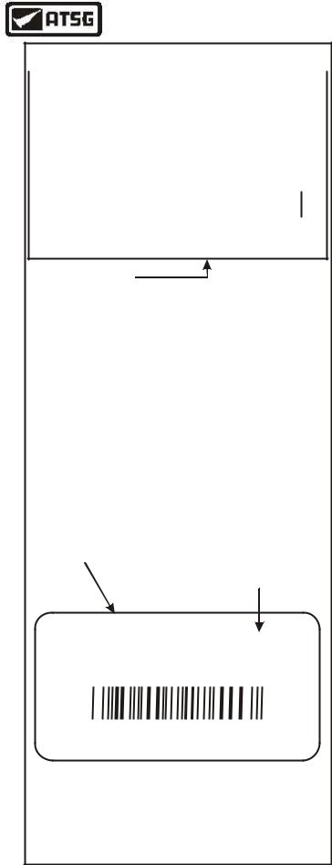
Typical Door I.D. Tag |
|
MFD BY FORD MOTOR CO IN USA |
DATE: 12/99 |
GVWR 4792LB 173KG |
FRONT GAWR |
2491LB 1129KG |
REAR GAWR |
2324LB 1054KG 2324LB 1054KG |
THIS VEHICLE |
CONFORMS TO ALL APPLICABLE FEDERAL |
MOTOR VEHICLE SAFETY, BUMPER AND THEFT PREVENTION
VIN 1FAPP6235VH103589 |
|
|
|
|
|
|
|
|
|
|
|
|
|
|
|
|
|
|
|
|
|
|
|
F8169 |
||||||||||||||||||||||||||||||
TYPE PASSENGER |
|
|
|
|
|
|
|
|
|
|
|
|
|
|
|
|
|
|
|
|
|
|
|
|||||||||||||||||||||||||||||||
|
|
|
|
|
|
|
|
|
|
|
|
|
|
|
|
|
|
|
|
|
|
|
RO114 |
|||||||||||||||||||||||||||||||
|
|
|
|
|
|
|
|
|
|
|
|
|
|
|
|
|
|
|
|
|
|
|
|
|
|
|
|
|
|
|
|
|
|
|
|
|
|
|
|
|
|
|
|
|
|
|
|
|
|
|
|
|
|
|
|
|
|
|
|
|
|
|
|
|
|
|
|
|
|
|
|
|
|
|
|
|
|
|
|
|
|
|
|
|
|
|
|
|
|
|
|
|
|
|
|
|
|
|
|
|
|
|
|
|
|
|
|
|
|
EXT PNT KM |
|
|
|
|
|
|
|
|
|
|
RC: 71 |
|
|
DSO 2450 |
||||||||||||||||||||||||||||||||||||||||
|
|
|
BRK |
|
|
IN TR TP PS |
|
|
|
|
|
R |
|
|
AXLE |
|
TR |
|
|
|
|
SPR |
||||||||||||||||||||||||||||||||
4 |
|
|
|
|
|
|
A2 |
|
|
|
|
|
H |
|
|
NN |
|
L |
|
|
|
DOMM |
||||||||||||||||||||||||||||||||
Axle Ratio Codes
NOTE: There are two different axle ratios listed for this transaxle used in the U.S.
NN = 3.693 Automatic
WW = 3.904 Automatic
Typical Transaxle
1st Digit Of Suffix
I.D. Tag
Also Identifies Ratio
And Original Engine
PVAA XS4P-DA
XS4P DA 01 9342 0769
B = Sigma Engine, 4.15 Ratio (Europe Only) C = 2.0L SPI Engine, 3.69 Ratio
D = 2.0L Z-Tec Eng, 3.90 Ratio
Copyright © 2004 ATSG
Figure 7
GEAR RATIO IDENTIFICATION
There are currently two different final drive axle ratios listed for this transaxle, in vehicles that are sold in the United States. The two different axle ratios are tied to the engine size in the vehicle. The easiest means of identification is on the door tag of the vehicle, as shown in Figure 7, and look for the two digit code under the word "AXLE".
Another means of identification is the first digit of the Suffix in the part number that is located on the transaxle identification tag, and is also shown in Figure 7. This will be the only means of identification if someone brings you a transaxle core to purchase. We have also shown you the European ratio, as we have already seen some of these cores in the U.S., and will not interchange into U.S. vehicles.
ELECTRONIC COMPONENT DESCRIPTION
POWERTRAIN CONTROL MODULE (PCM)
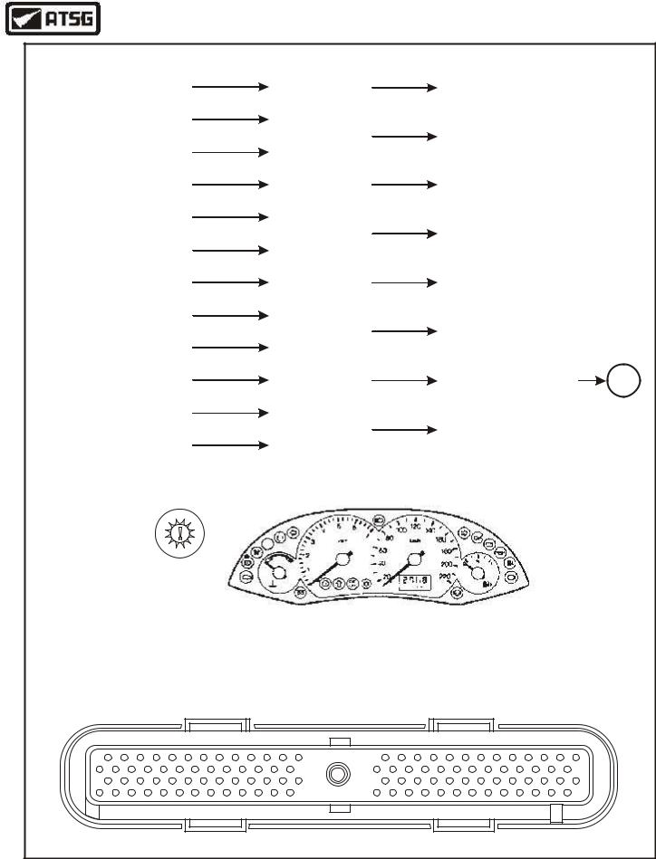
The Powertrain Control Module (PCM) controls engine functions and provides total control of the 4F27E transaxle. The PCM monitors various input signals from several sensors and switches, as shown in Figure 8, and will then respond by operating solenoids for control of the line pressure, the shift scheduling and apply and release of the Torque Converter Clutch (TCC).
The PCM may also store Diagnostic Trouble Codes (DTC's) related to detected transaxle faults. If faults are detected, it will alert the driver by turning ON the Malfunction Indicator Lamp (MIL) located in the instrument cluster, as shown in Figure 8.
"FAIL-SAFE" OPERATION
If the transaxle loses electronic control, as in blown fuse, it will operate in a fail-safe mode with the following features:
 Maximum line pressure in all positions.
 Fully functional P, R and N positions.
 Operation in 3rd gear only with coast braking, when selector is in any forward range.
 TCC released in all positions.
Continued on Page 11
AUTOMATIC TRANSMISSION SERVICE GROUP |
9 |
|
Technical Service Information
INPUTS |
POWERTRAIN |
|
OUTPUTS |
|
||||
ELECTRONIC IGNITION |
|
|
|
|
ELECTRONIC PRESSURE |
|
||
(EI) SYSTEM |
|
|
|
CONTROL |
|
CONTROL (EPC) SOLENOID |
|
|
|
|
|
|
|
MODULE (PCM) |
|
|
|
|
|
|
|
|
|
|
|
|
TRANSMISSION RANGE |
|
|
|
|
|
|
|
|
(TR) SENSOR |
|
|
|
|
|
|
|
|
|
|
SHIFT SOLENOID "A" |
|
|||||
|
|
|
|
|
|
|
(SSA) |
|
TURBINE SHAFT SPEED |
|
|
|
|
|
|
||
|
|
|
|
|
|
|
||
(TSS) SENSOR |
|
|
|
|
|
|
|
|
|
|
|
|
|
|
|
|
|
|
|
|
|
|
|
|
|
|
OUTPUT SHAFT SPEED |
|
|
|
|
|
SHIFT SOLENOID "B" |
|
|
(OSS) SENSOR |
|
|
|
|
|
(SSB) |
|
|
|
|
|
|
|
|
|
|
|
THROTTLE POSITION |
|
|
|
|
|
|
|
|
(TP) SENSOR |
|
|
|
|
|
|
|
|
|
|
SHIFT SOLENOID "C" |
|
|||||
|
|
|
|
|
|
|
(SSC) |
|
INTAKE AIR TEMP |
|
|
|
|
|
|
||
|
|
|
|
|
|
|
||
(IAT) SENSOR |
|
|
|
|
|
|
|
|
|
|
|
|
|
|
|
|
|
|
|
|
|
|
|
|
|
|
ENGINE COOLANT |
|
|
|
|
|
SHIFT SOLENOID "D" |
|
|
TEMP (ECT) SENSOR |
|
|
|
|
|
(SSD) |
|
|
|
|
|
|
|
|
|
|
|
TRANSMISSION FLUID |
|
|
|
|
|
|
|
|
TEMP (TFT) SENSOR |
|
|
|
|
|
|
|
|
|
|
SHIFT SOLENOID "E" |
|
|||||
|
|
|
|
|
|
|
(SSE) |
|
MASS AIR FLOW |
|
|
|
|
|
|
||
|
|
|
|
|
|
|
||
(MAF) SENSOR |
|
|
|
|
|
|
|
|
|
|
|
|
|
|
|
|
|
|
|
|
|
|
|
|
|
|
AIR CONDITIONING |
|
|
|
|
|
TRANSMISSION CONTROL |
O/D |
|
(AC) SWITCH |
|
|
|
|
|
INDICATOR LAMP (TCIL) |
OFF |
|
|
|
|
|
|
|
|
|
|
TRANSMISSION CONTROL |
|
|
|
|
|
|
|
|
SWITCH (TCS) |
|
|
|
|
|
|
|
|
|
|
MALFUNCTION INDICATOR |
|
|||||
|
|
|
|
|
|
|
LAMP (MIL) |
|
BRAKE PEDAL POSITION |
|
|
|
|
|
|
||
|
|
|
|
|
|
|
||
(BPP) SWITCH |
|
|
|
|
|
|
|
|
|
|
|
|
|
|
|
|
|
|
|
|
|
|
|
|
|
|
|
|
|
|
|
|
|
|
|
|
|
|
|
|
|
|
|
|
|
|
|
|
|
|
|
|
|
The "Powertrain Warning Indicator" is located on the left side of the instrument cluster as shown above and is Orange in color.
"PCM IS LOCATED BEHIND THE RIGHT HAND KICK PANEL"
PCM PIN IDENTIFICATION
1 |
26 |
79 |
104 |
Copyright © 2004 ATSG
Figure 8
10 |
AUTOMATIC TRANSMISSION SERVICE GROUP |
|
Technical Service Information
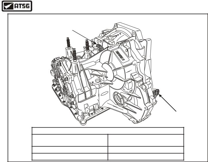
TURBINE AND OUTPUT SPEED SENSORS |
||
Turbine Speed Sensor |
|
|
|
P |
|
|
V |
|
X |
AA |
|
S |
||
4P |
X4 |
|
|
B |
|
|
F |
S |
|
0 |
P |
|
1 |
|
|
9 |
- |
|
34 |
BF |
|
2 |
|
|
076 |
|
|
|
9 |
ord |
|
|
F |
|
|
|
|
Output Speed Sensor |
TRANSAXLE SPEED SENSOR RESISTANCE CHART |
||
Transaxle |
|
Ohms Resistance At |
Component |
|
20°C (70°F) |
Turbine Speed Sensor (TSS) |
|
330 - 390 Ohms |
Output Speed Sensor (OSS) |
|
720 - 800 Ohms |
Figure 9
TURBINE SHAFT SENSOR
The Turbine Shaft Speed (TSS) sensor mounts on the transaxle case externally, as shown in Figure 9, and is a magnetic pickup that the PCM monitors to determine the rotating speed of the input shaft. The PCM uses the TSS sensor signal to determine EPC pressure and TCC control strategy.
There is a resistance chart found in Figure 9 to check the Turbine Shaft Speed sensor.
OUTPUT SHAFT SENSOR
The Output Shaft Speed (OSS) sensor mounts on the transaxle case externally, as shown in Figure 9, and is a magnetic pickup that the PCM monitors to determine the rotating speed of the output shaft. The PCM uses the OSS sensor signal to determine EPC pressure, shift scheduling and TCC control strategy.
There is a resistance chart found in Figure 9 to check the Output Shaft Speed sensor.
TRANSMISSION RANGE (TR) SENSOR
The Transmission Range (TR) sensor is mounted on the transaxle at the manual control lever, as shown in Figure 10. The PCM uses the range sensor for the selected gear, and for EPC pressure control strategy. The TR sensor also contains the Neutral/Start and the backup lamp circuits. We have provided you with a complete range sensor wiring schematic in Figure 10.
Continued on Page 13
AUTOMATIC TRANSMISSION SERVICE GROUP |
11 |
|