

README
.pdf
|
August 9, 2011 |
MATLAB Support Package for Vernier |
|
SensorDAQ User's Guide |
|
Contents |
|
Introduction ............................................................................................................................................................................ |
2 |
Package Requirements........................................................................................................................................................ |
2 |
Installation Instructions .......................................................................................................................................................... |
3 |
Running Setup:.................................................................................................................................................................... |
3 |
Getting Started........................................................................................................................................................................ |
4 |
Using SensorDAQ with Data Acquisition Toolbox............................................................................................................... |
4 |
Reading Sensor Data ........................................................................................................................................................... |
4 |
Create a Session .............................................................................................................................................................. |
5 |
Add a Sensor Channel ..................................................................................................................................................... |
5 |
Get the Scaling Function ................................................................................................................................................. |
5 |
Read Data from the Sensor............................................................................................................................................. |
5 |
Using Terminal Inputs and Outputs .................................................................................................................................... |
6 |
Using Analog I/O and Counters....................................................................................................................................... |
6 |
Using Digital I/O .............................................................................................................................................................. |
6 |
Cleaning Up ......................................................................................................................................................................... |
7 |
Accessing Help .................................................................................................................................................................... |
7 |
Reference Guide and Advanced Topics .................................................................................................................................. |
8 |
Using the Support Package with Multiple Devices ............................................................................................................. |
8 |
Using Clocked Acquisition with SensorDAQ........................................................................................................................ |
8 |
Using Different Calibration Types ....................................................................................................................................... |
8 |
Manually Calibrating Sensors.............................................................................................................................................. |
9 |
Using Different Input Modes .............................................................................................................................................. |
9 |
Troubleshooting.................................................................................................................................................................... |
11 |
I can't connect to my SensorDAQ device.......................................................................................................................... |
11 |
My scaled sensor readings are inaccurate........................................................................................................................ |
11 |
1
August 9, 2011
Introduction
The Vernier SensorDAQ is a hardware interface for Vernier sensors. As of MATLAB R2011b, the SensorDAQ can be accessed from MATLAB using Data Acquisition Toolbox. The Support Package for Vernier SensorDAQ (the Support Package from now on) contains several helper functions to simplify the process of collecting data from SensorDAQ.
The SensorDAQ supports up to three Vernier analog sensors and one Vernier digital sensor. It also has a terminal block with:
Two analog inputs
An analog output
A counter input
Four digital input/outputs
+5V
Ground
Using the Support Package, it's possible to access the Vernier analog sensors as well as all terminal block inputs and outputs. Vernier digital sensors are not supported at this time.
Package Requirements
Windows
MATLAB R2011b or later (32 or 64 bit)
Data Acquisition Toolbox
National Instruments NI-DAQmx driver (shipped with the SensorDAQ or found on NI's website)
2
August 9, 2011
Installation Instructions
Before running setup, make sure that the NI-DAQmx driver is installed on the system. NI-DAQmx is shipped with the SensorDAQ, or can be found online on NI's website.
Running Setup:
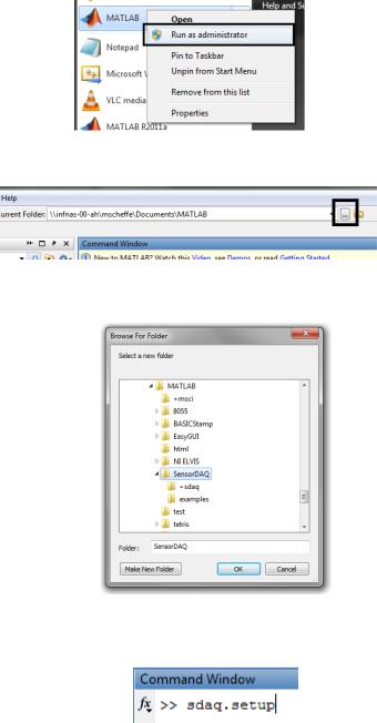
1. Run MATLAB as an administrator by right clicking on the MATLAB icon and selecting “Run as administrator”.
2.Click on the ellipsis (…) to the right of the “Current Folder” prompt at the top of the screen
3.Navigate to this folder (“…\SensorDAQ”) and click “OK”.
4.In the Command Prompt, type “sdaq.setup” without the quote marks and hit Enter
5.Setup should complete automatically. If a warning occurs, MATLAB could not save the search path. Make sure MATLAB is running with administrative privileges and that it has write access to pathdef.m.
3

August 9, 2011
Getting Started
The MATLAB Support Package for SensorDAQ is intended to be used in conjunction with Data Acquisition Toolbox. Users should be familiar with using Data Acquisition Toolbox's Session-based interface. Users should also be familiar with using MATLAB packages; both the Support Package and Data Acquisition Toolbox use packages to scope their functions.
Using SensorDAQ with Data Acquisition Toolbox
In general, the workflow for accessing a SensorDAQ device using Data Acquisition Toolbox (DAT) and the Support Package is as follows:
Create a DAT |
Optional: |
session using |
Configure the |
sdaq.createSession |
session |
Add channels to the session using the Support Package
Optional: |
Use DAT session |
|
methods to read or |
||
For sensors, create |
||
write to the |
||
a scaling object |
||
SensorDAQ |
||
|
The rest of this guide will describe how to complete specific tasks using the SensorDAQ, such as reading data from a sensor. In addition to this guide, the examples directory of this guide contains several detailed examples
For simplicity, the following sections assume the following scenario:
Only one SensorDAQ device is connected to the computer. If multiple SensorDAQ devices are connected, see "Using the Support Package with Multiple Devices" in the Reference Guide and Advanced Topics section.
Only a single sample is retrieved at a time (“unclocked single scan acquisition”). To get multiple samples continuously or for a specified duration, see “Using Clocked Acquisition with SensorDAQ" in the Reference Guide and Advanced Topic section.
Reading Sensor Data
At this time, Data Acquisition Toolbox and the Support Package only support Vernier analog sensors. Reading sensor data from a device is a four step process.
1) Create a session object (note that the function call is prefixed with “sdaq.” and not “daq.”)
s = sdaq.createSession;
2) Add a sensor channel to the session:
sdaq.addSensor(s,1,sdaq.Sensors.Barometer); % sensor channel 1
3) Get the scaling function that converts the raw sensor voltage value into physical units
scale = sdaq.getScaleFun(sdaq.Sensors.Barometer);
4) Read a sample of voltage data from the device and scale it using the scaling function
rawdata = s.inputSingleScan; data = scale(rawdata);
data = scale(s.inputSingleScan); % the two statements can be combined
More information on each step can be found below.
4
August 9, 2011
Create a Session
s = sdaq.createSession;
Data Acquisition Toolbox interfaces with devices using a special Session object. sdaq.createSession creates a session suitable for use with SensorDAQ. This session will be used to actually read data from the device; keep track of it!
Add a Sensor Channel
sdaq.addSensor(s,1,sdaq.Sensors.Barometer);
addSensor adds a sensor channel to the session. The sensor can be connected to any of the three analog sensor channels (labeled Ch.1, Ch.2, and Ch.3); this channel number is specified as the second argument.
The sensor type is specified using sdaq.Sensors, a structure that contains the list of Vernier sensors with corresponding configuration information.To see the list of available sensor types, type:
properties(sdaq.Sensors)
To access information on a particular sensor (a barometer in this case), type:
sdaq.Sensors.Barometer |
%replace Barometer with the name of the sensor |
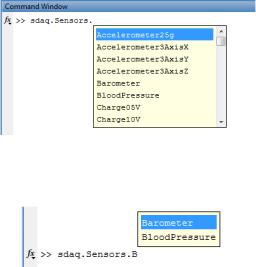
Using tab completion to make finding sensors easier is recommended. To use tab completion, type "sdaq.Sensors." and hit the Tab key. A list like the following will pop up:
Navigate to the sensor using the mouse or arrow keys and hit Enter. Alternatively, narrow down the list by typing more letters:
Get the Scaling Function
scale = sdaq.getScaleFun(sdaq.Sensors.Barometer);
SensorDAQ returns sensor readings as raw voltage values. scale is a scaling function that converts these raw voltages into useful sensor data with correct physical units (in this case, pressure data). To see the physical units, type:
scale.Units
Some sensors may have multiple possible output types. To select which type to use, see "Using Different Calibration Types" in the Reference Guide and Advanced Topics section of this guide.
Read Data from the Sensor
data = scale(s.inputSingleScan);
5
August 9, 2011
This line actually contains two different functions. s.inputSingleScan is a method that retrieves one sample of voltage data rom this device; scale is the scaling function described above.
If this line does not seem to be returning accurate results, the sensor may need to be manually calibrated using a two-point test. For more information, see "Manually Calibrating Sensors" in the Reference Guide and Advanced Topics section of this guide.
Using Terminal Inputs and Outputs
The SensorDAQ has several input and output channels connected to its terminal block. These include two analog inputs (pins 11 and 12), an analog output (pin 9), a counter input (pin 7), and four digital input/outputs (pins 1-4). All but the digital IO channels can be accessed through the Session-based interface. The digital IO channels can be accessed using the older Legacy interface (32-bit MATLAB only).
Using Analog I/O and Counters
The process for using analog inputs/outputs and the counter input with the Session-based interface is almost identical to the process for using a sensor channel. First, create a Data Acquisition Toolbox session:
s = sdaq.createSession;
Then use the appropriate function to add the channel to the session:
Analog Input |
sdaq.addAnalogInput(s,0) % analog input channel 0 |
|
|
Analog Output |
sdaq.addAnalogOutput(s) |
|
|
Counter Input |
sdaq.addCounterInput(s) |
|
Finally, use inputSingleScan/outputSingleScan to read from or write to the channel.
Analog Input |
s.inputSingleScan |
|
|
Analog Output |
s.outputSingleScan(1) |
|
|
Counter Input |
s.inputSingleScan |
|
Examples (with detailed explanation) for each input and output type can be found in the examples directory.
Note that both the analog inputs and counter input have multiple input modes. For more information see, "Using Different Input Modes" in the Reference Guide and Advanced Topics section of this guide.
Using Digital I/O
The four digital IO channels must be accessed using Data Acquisition Toolbox’s legacy interface. The legacy interface is compatible with 32-bit MATLAB only.
The following example shows how to access digital IO line 0 (pin 1 on the terminal) on a device called 'Dev1' using the legacy interface. For more information and similar examples, refer to the documentation for digitalio.
% Create a digitalio object
dio = digitalio('nidaq','Dev1');
%Add line 0 to the digitalio object addline(dio,0,'In');
%Read the line
6
August 9, 2011
getvalue(dio)
%Change the line to an output dio.Line.Direction = 'Out';
%Set the channel high putvalue(dio,1);
%Clean up
delete(dio);
Cleaning Up
After finishing with a session, delete it to free up memory by typing:
delete(s);
Accessing Help
All Support Package functions have built in help accessible through the MATLAB help function. For example, to access help for addChannel, type:
help sdaq.addChannel
Help for each function describes proper syntax for the function and gives examples on its use. Also, each help text contains links to help for other related functions.
7
August 9, 2011
Reference Guide and Advanced Topics
Using the Support Package with Multiple Devices
By default, Support Package functions automatically detect one device connected to the system. If multiple SensorDAQs are connected, a device name must be manually specified in function calls. This will always be the first argument after the default arguments; for example, to specify a SensorDAQ called 'Dev1' when calling addSensor, type:
sdaq.addSensor(s,1,sdaq.Sensors.Barometer,'Dev1');
Device names are defined by the NI software and typically look like 'DevX', where X is a number. To get a list of devices with device names and device types, type:
daq.getDevices
Using Clocked Acquisition with SensorDAQ
Clocked acquisition can be used to collect multiple samples at a specified sample rate. The process for clocked acquisition is essentially that same as for unclocked, except for two details:
The session must be configured for clocked acquisition
startForeground and startBackground must be used instead of inputSingleScan/outputSingleScan
Configuring the session involves changing the session's properties, especially Rate and DurationInSeconds. These should be changed to reflect the desired acquisition criteria.
s = sdaq.createSession; s.DurationInSeconds = 2; % ... add channel(s)
rawdata = s.startForeground; % collects 2 seconds worth of data
data = scale(rawdata); % for sensors, apply the appropriate scaling function
IMPORTANT: Data Acquisition Toolbox requires that the Rate is set before adding any SensorDAQ channels to a session. Changing the rate after a SensorDAQ channel has been added will cause an error. For this reason, it is recommended that the session be configured for clocked acquisition before any channels are added.
An example of clocked acquisition from a sensor is included in the examples directory. For information, see this demo on using daq.startForeground, and this demo on using daq.startBackground.
Using Different Calibration Types
Some sensors have multiple calibration types, often with different output units. For example, barometers can output pressure in kPa, mmHg, and inHg. To see a list of calibration types, retrieve the sensor information from the Sensors class:
>> sdaq.Sensors.Barometer ans =
Name: 'Barometer' Channel: 5
CalEq: 'linear' Cal0Consts: [81.9520 7.8000 0]
Cal0Units: '(KPA)'
Cal1Consts: [614.8400 58.5200 0] Cal1Units: '(MMHG)'
8
August 9, 2011
Cal2Consts: [24.2150 2.2920 0]
Cal2Units: '(INHG)'
A sensor can have up to three calibration types numbered 0, 1, and 2. The calibration type can be specified as an optional argument to getScaleFun
scale = sdaq.getScaleFun(sdaq.Sensors.Barometer,1);
The above line would specify that the scaling object should use calibration type 1 (in this case, returning mmHg instead of kPa).
Manually Calibrating Sensors
The calibration information for a sensor defines a calibration equation and default constants for this equation. Some sensors may not adhere to these standard values and will have to be calibrated manually using a two-point test. Most sensors use a linear calibration relationship, so this section will focus on these sensors. The process for nonlinear sensors will be similar.
To perform a two point test, obtain two unscaled readings at two known reference points. From these two pairs of points, the calibration constants can be calculated using a simple linear relationship.
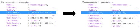
For example, a hypothetical thermocouple sensor reads .6 volts at 0°C and .7 volts at 20°C. From this, one can calculate that the calibration equation should be . This gives the two calibration constants: -120 and 200.
To change the calibration constants, manually edit the sensor object in the Sensors class file. To open the class file, type:
edit sdaq.Sensors
Find the entry for the sensor type. Change the appropriate constants and save the file. For example, to set the constants for the above thermocouple example, change the following line:
Then save the file (Ctrl+S). Now, when creating a scaling object for a thermocouple, the scaling object will use the new constants to scale the values properly.
Using Different Input Modes
By default, analog inputs are set up in "single ended" mode. This means that the voltage measured will be relative to ground. For analog input 0 (pin 11), the input can be set up to measure in "differential" mode. This will measure the voltage difference between analog inputs 0 and 1 (pins 11 and 12). To add analog input 0 in differential mode to a session, type:
sdaq.addAnalogInput(s,0,'Dev1','Differential');
By default, the counter input is set up in "edge count" mode. This will count state changes on pin 7 on the device. The counter can also be set up to measure frequency of a digital signal. To add the counter input in frequency mode, type:
9
August 9, 2011
sdaq.addCounter(s,'Dev1','Frequency');
Note that in both cases the input mode cannot be set if the device name is not specified (see "Using the Support Package with Multiple Devices" above).
10