

Курсова по ПКІС / PH1
.pdfUpper value of the simulation
Parameter: |
P87 |
Menu path: |
SERVICE / SIMULATION / UPPER VALUE |
Description: |
Highest value of the simulation |
6.4.5.8 Temperature simulation
Default value:
pH measurement |
ORP measurement |
DO measurement |
|
|
|
14 pH |
1000 mV |
8.24 ppm |
|
|
|
This function helps the user to check the outputs and the additional processing instruments connected to the output. To start simulation the instrument must return to Measuring mode.
Temperature simulation mode
Parameter: |
P84: b |
|
|
|
|
|
|
|
|
|
Menu path: |
SERVICE / TEMP. SIMULATION / MODE |
|
|
|
|
Default value: |
||||
|
|
|
|
|
|
|
|
OFF |
||
Description: |
Temperature simulation mode: |
|
|
|
|
|
|
|
|
|
|
OFF |
|
No temperature simulation |
|
|
|
|
|
|
|
|
FIX VALUE |
|
Simulation of a fixed lower range temperature value |
|
|
|
|
|
|
|
|
TRIANGLE WAVE |
|
The simulated value changes linearly between the set low |
|
|
|
|
|
|
|
|
|
|
and high values with an adjustable cycle time |
|
|
|
|
|
|
|
|
|
|
|
|
|
|
|
|
|
|
|
|
|
|
|
|
|
|
|
|
|
|
|
|
|
|
|
|
|
|
|
|
|
|
|
|
|
|
|
|
|
|
|
BKI 11 ATEX 0012 X le00100a0600p_03 51 / 60
Temperature simulation cycle
Parameter: |
P88 |
|
Menu path: |
SERVICE / TEMP. SIMULATION / TIME |
|
Description: |
Cycle time of the temperature simulation |
|
Bottom value of the temperature simulation |
||
Parameter: |
P89 |
|
Menu path: |
SERVICE / TEMP. SIMULATION / BOTTOM VALUE |
|
Description: |
Lowest value of the temperature simulation |
|
Upper value of the temperature simulation |
||
Parameter: |
P90 |
|
Menu path: |
SERVICE / TEMP. SIMULATION / UPPER VALUE |
|
Description: |
Highest value of the temperature simulation |
|
6.4.5.9 |
Load default values |
|
Parameter: |
- |
|
Menu path: |
SERVICE / DEFAULTS / LOAD DEFAULT |
|
Description: |
This command loads all default values of the instrument. |
|
|
|
After loading the default values the parameters can freely be changed, the effect of the |
|
|
changes does not affect the measurement until the user exits programming mode and |
|
|
returns to measurement mode. Before loading the defaults the software asks for a |
6.4.5.10 |
Restart |
confirmation warning the user that all user parameters will be lost! |
|
||
Parameter: |
- |
|
Menu path: |
SERVICE / RESTART |
|
Description: |
Restarts the instrument (Cold boot) (Reloads parameters from the non-volatile memory) |
|
Default value: 60 sec
Default value: 0 ºC
Default value: 50 ºC
Default value:
-
Default value:
–
52 / 60 le0010a0600p_03 BKI 11 ATEX 0012 X

6.5. PH SENSOR CALIBRATION
This function is for periodic calibration of the pH sensor.
Entering the SERVICE / SENSOR CALIBRATION menu the instrument will display a warning message that the user is about to change critical parameters of the measurement system. The user can enter the menu by pressing the  (OK) button or exit to the previous menu by pressing the
  (NO) button.
In case of calibration, after sensor replacement, please handle first calibration with high priority. The system will inquire this in the next dialog box. In the event of initial calibration, press the  OK button. In this case, all parameters and counters related to the sensor will be reset to default.
We should press  NO button, in case it is not the first calibration.
In the SENSOR INFO page the slope and offset voltage of the sensor can be checked (see chapter 6.2).
6.5.1. Editing one item of the calibration table
(SERVICE | SENSOR CALIBRATION | VIEW/EDIT TABLE)
Calibration of the pH sensor is done using this table with min. 2 or max. 8 elements. By default the table contains 2 elements (0 and 14pH). The instrument is ready to measure with these two elements in the table. Any change in the calibration table applies instantly! The two minimal elements of the table cannot be erased only edited.
The selected element of the list (table) can be edited by pressing the E button. Then we get a special box editor.
One line of the list consists of two values. The left one (BUFFER VALUE) shows the nominal value of the used pH buffer solution. The right one (SENSOR VALUE) indicates the uncalibrated but temperature compensated value measured with this buffer solution.
VIEW/EDIT TABLE 0: 0.00 0.00 1: 14.00 14.00
BKI 11 ATEX 0012 X le00100a0600p_03 53 / 60

Adding, modifying a calibration point
The following special screen helps the user to set a calibration point. The user can see the uncalibrated measured values and also the pair values of the selected table line.
1. Value, measurable without sensor calibration
2. Trend display for monitoring installation.
The upper part of the bargraph symbolizes the increasing trend, the bottom part of the bargraph symbolizes the decreasing trend. The filling rate is in accordance with the measure of change. If the bargraph is empty, the measured value is constant.
3.Measured value with calibration.
4.The BUFFER VALUE is editable using the  ,
,  and
and  buttons. The user has to enter the nominal pH value of the measured buffer solution.
5.The measured value can be copied to the stored SENSOR VALUE by pressing the  +
+  buttons simultaneously. Then the software starts an algorithm to check if the measured value is stable or not. When the value is stored in the SENSOR VALUE field, a READY message appears on the bottom of the display.
The measured value can be copied to the stored SENSOR VALUE by pressing the  +
+  buttons simultaneously. If the two values of the data pair differ in more than ±0.5 pH from each other the software shows an error message at the bottom line of the screen.
By pressing the E button the instrument checks the edited calibration data pair and if it is OK the software returns to the calibration table. If not a dialogue window will appear and inform the user.
Exit from the calibration table by pressing the  button.
Damping check:
When pressing the  +
+  buttons the software checks if the calibration value to be stored is constant. After the buttons are pressed the measured pH value must be stabilized in 30 seconds otherwise the value will not be stored and a FAILED! message will appear on the screen. Change in the measured value (1) can be followed on the trend bargraph (2). If the cause of a fluctuation or error is eliminated, storing of the calibration points can be repeated by pressing the
  +
+  buttons again.
54 / 60 le0010a0600p_03 BKI 11 ATEX 0012 X

6.5.2. Adding an item to the calibration table
(SERVICE | SENSOR CALIBRATION | ADD ITEM)
This menu point adds a line to the table and enters to view/edit table display at the same time. Editing is done as described above.
6.5.3. Deleting an element of the calibration table
(SERVICE | SENSOR CALIBRATION | DELETE ITEM)
This menu point lets the user delete a line (element) of the table. Pressing the E on the selected line deletes it from the table. Exit from the list by pressing the  button.
6.5.4. Reset the calibration table to default
(SERVICE | SENSOR CALIBRATION | RESET TO DEFAULT)
This function resets the sensor calibration data to default (0 and 14 pH). It is ineffective to other operating parameters.
6.5.5. Calibration procedure
1.Enter to menu point „SENSOR CALIBRATION - VIEW / EDIT TABLE” as described in Chapter 6.5.1
2.Rinse the pH electrode and temperature sensor with distilled water then dry up gently using a soft rag.
3.Immerse the electrode as well as the temperature sensor into the buffer solution.
4.Select one existing line of the calibration table or add a new item to the table.
5.In the „BUFFER VALUE:” field enter the pH value of the first buffer solution corrected to the actual temperature – use the  ,
, and
and  buttons - . (The temperature corrected pH values of the buffer solution usually are listed on the label of the bottle.)
6.Observe the damping of „SENSOR:” and „MEASURED:” values. This is helped by the bargraph near them. If values are settled press  +
+  buttons simultaneously to store the actual measured value which will appear in the „SENSOR VALUE:” field. If user cannot get a clear measurement (the value is constantly changing) the sensor should be cleaned as described in chapter 4.3 and recalibrated again. If the electrode still cannot be calibrated it has to be replaced with a new one!
7.Exit to „VIEW / EDIT TABLE” by pressing the E button.
8.Repeat steps 2…6 for every desired calibration point (max. 8)
9.Exit programming mode by pressing the  display, and check the calibrated measurement state („UNCAL” message disappears from the display.
BKI 11 ATEX 0012 X le00100a0600p_03 55 / 60

6.6. DO SENSOR CALIBRATION
This function is for periodic calibration of the DO sensor.
The sensor is aging during the usage of the instrument. When the life-time of the sensor is over the sensor should be replaced. In case of sensor replacement the sensor should be calibrated compensating the aging. Calibration of the sensor has to be done in two points: (ZERO – zero point and SPAN – saturated value)
ZERO calibration can be performed with 5% sodium sulphite referential liquid, SPAN (saturated value) calibration can be performed with saturated zero salinity referential liquid or air. Value of atmospheric pressure should be set before calibration process (see 6.4.1.8.)
Entering the SERVICE / SENSOR CALIBRATION menu the instrument will display a warning message that the user is about to change critical parameters of the measurement system. The user can enter the menu by pressing the  (OK) button or exit to the previous menu by pressing the
  (NO) button.
In case of calibration, after sensor replacement, please handle first calibration with high priority. The system will inquire this in the next dialog box. In the event of initial calibration, press the  OK button. In this case, all parameters and counters related to the sensor will be reset to default.
We should press  NO button, in case it is not the first calibration.
6.6.1. Calibration of saturated value (100%)
(SERVICE / SENSOR CALIBRATION / CAL. IN AIR (SPAN))
Rinse the DO sensor with distilled water then dry up gently using a soft rag. Immerse the sensor into saturated, zero salinity referential liquid or hold the sensor into air.
Please wait until the measured value (2) get stabilized. Change in the measured value (2) can be followed on the trend bargraph (1). Achieving proper calibration atmospheric pressure (3) and relative humidity (4) should be entered. In accordance to these values and the measured
temperature the instrument calculates the DO concentration, which can be edited in the last line (5).
Damping check:
When pressing the E button at the last line, a warning message appears asking do we really want to store the calibration data. By pressing the  [yes – OK] button, the instrument checks the stability of the measured value and if it remains unchanged during a given time period, the instrument stores the calibration. Changes of the measured value can be checked on the display (2) and the trend bargraph (1) also indicates changes of the measured value. When the measured value got stabilized, READY! message will appear on the bottom of the screen. If damping check procedure is unsuccessful, FAILED! message will appear on the bottom of the screen. When the error caused by changes or fluctuations became resolved, then calibration-point storing procedure can be repeated.
56 / 60 le0010a0600p_03 BKI 11 ATEX 0012 X

6.6.2. Calibration of Zero point (0%)
(SERVICE / SENSOR CALIBRATION / CAL. IN ZERO SOL.)
Rinse the DO sensor with distilled water then dry up gently using a soft rag. Immerse the sensor into 5% sodium sulphite referential liquid.
Please wait until the measured value (2) get stabilized. Change in the measured value (2) can be followed on the trend bargraph (1).
When pressing the E button at the last line, a warning message appears asking do we really want to store the calibration data. By pressing the  [yes – OK] button we enter the damping check procedure described in the previous point.
6.6.3. Calibration with referential DO instrument
(SERVICE / SENSOR CALIBRATION / CAL. IN SPAN SOL.)
With this function the instrument can be calibrated to a referential (already calibrated) instrument. In this case basic settings (atmospheric pressure, temperature) should be the same.
Rinse the DO sensor with distilled water then dry up gently using a soft rag. Immerse the sensor into saturated referential liquid with zero salinity or hold the sensor into air.
Please wait until the measured value (2) get stabilized. Change in the measured value (2) can be followed on the trend bargraph (1).
Read the measurement value of the referential instrument and enter this value to the edit field (3).
When pressing the E button at the last line, a warning meassage appears asking do we really want to store the calibration data. By pressing the  [yes – OK] button we enter the damping check procedure described in 6.6.1 point.
6.6.4. Reset the calibration table to default
(SERVICE | SENSOR CALIBRATION | DELETE ITEM)
This function resets the sensor calibration data to default. It is ineffective to other operating parameters.
6.6.5. Reset Timer
This function resets the inner timer of the DO electrode life-time monitoring routine.
BKI 11 ATEX 0012 X le00100a0600p_03 57 / 60

6.7. ERROR CODES
Code |
Message on the screen |
Error description |
|
|
|
1 |
MEMORY ERROR |
Memory error in the electronics |
|
||
2 |
NO INPUT SIGNAL |
Hardware error |
|
|
|
3 |
EE COM. ERROR |
Hardware error |
|
|
|
4 |
MATH. OVERLOAD |
Display overflow |
|
|
|
5 |
SENS. SERVICE! |
Sensor |
slope and |
offset are |
out of |
|
tolerance limit. |
|
|
||
|
|
|
|
||
16 |
EE CHK ERROR |
Parameter checksum error. |
|
||
|
|
|
|
|
|
17 |
INTEGRITY ERROR |
Incorrect |
parameter |
values. |
Stored |
|
|
parameters are damaged. |
|
||
|
|
|
|
|
|
18 |
AC COM. ERROR |
Hardware error |
|
|
|
19 |
RELAY ERROR |
Hardware error |
|
|
|
- |
TEMP. ERROR |
Temperature sensor error |
|
||
|
|
|
|
|
|
- |
CALIBRATION ERROR |
Logic error |
|
|
|
- |
POINT PAIR ERR. |
Logic error |
|
|
|
Procedure
Contact the service! Contact the service! Contact the service!
Check the programming!
Check or clean the sensor and do a calibration. Check the correct operation of the sensor and the installation!
Restart the unit in SERVICE / RESTART menu (or power off and on the instrument) and check / repeat programming! If the problem persists contact the service!
Restart the unit in SERVICE / RESTART menu (or power off and on the instrument) and check / repeat programming! If the problem persists contact the service!
Contact the service! Contact the service!
Check the connection of the temperature sensor. The unit will compensate to 25ºC!
Check the sensor calibration table! Check the sensor calibration table!
le00100a0600p_02.doc 2011. November
Nivelco reserves the right to change technical data without notice!
58 / 60 le0010a0600p_03 BKI 11 ATEX 0012 X

60 / 59 03_le00100a0600p X 0012 ATEX 11 BKI
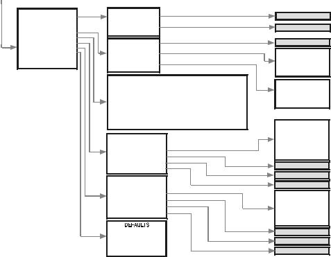
6.8 MENUMAP
MAIN MENU
----------------------
BASIC SETUP OUTPUT SETUP SERVICE
BASIC SETUP
-----------------------------------
MEASURING UNIT(DO)
DAMPING. TIME
TEMP. COMPENSATION
SALINITY CORRECTION(DO)
PRESSURE CORRECTION(DO) 
MEASURING UNIT
--------------------------------
ppm mg/l %sat
DAMPING TIME
TEMP. COMPENSATION
--------------------------------
MODE
UNIT
MANUAL VALUE
MANUAL VALUE
PRESSURE CORRECTION
--------------------------------
UNIT
MANUAL VALUE
OUTPUT SETUP |
ANALOG OUTPUT |
|
--------------------------------- |
-----------------------------------ANALOG OUTPUT |
CURRENT MODE |
4 mA VALUE |
|
RELAY OUTPUT |
20 mA VALUE |
SERIAL OUTPUT |
ERROR MODE |
|
MANUAL VALUE |
RELAY OUTPUT
---------------------------------
MODE
FUNCTION 4 mA VALUE 20 mA VALUE DELAY TIME INVERTING
SERIAL OUTPUT
---------------------------------
ADDRESS
MODE
---------------------------------
AUTO
MANUAL
OFF
UNIT
---------------------------------
C°
F°
MANUAL VALUE
UNIT
---------------------------------
C°
F°
MANUAL VALUE
CURRENT MODE
---------------------------------
AUTO
MANUAL
4 mA VALUE 20mA VALUE
ERROR MODE
---------------------------------
HOLD 3.8 mA 22 mA
MANUAL VALUE
MODE
---------------------------------
OFF pH/ORP/DO TEMP
ON ERROR
FUNCTION
---------------------------------
HYSTERESIS
WINDOW
DELAY TIME
INVERTING
---------------------------------
YES
NO
ADDRESS
X 0012 ATEX 11 BKI 03_le0010a0600p 60 / 60
SERVICE
-----------------------------------
SECURITY
OUTPUT TEST SENSOR CALIBRATION pH/ORP/DO SIMULATION
TEMP. SIMULATION DEFAULTS
RESTART
SECURITY
---------------------------------
USER LOCK
SERVICE LOCK
OUTPUT TEST
---------------------------------
ANALOG OUTPUT
RELAY OUTPUT
SERIAL OUTPUT
SENSOR CALIBRATION / SETUP
pH: |
|
ORP: |
|
|
DO: |
|
|||||
|
VIEW/EDIT TABLE |
|
SET |
ZERO POINT |
|
|
ZERO CAL. IN LIQUID |
||||
|
|
|
ADD ITEM |
|
|
|
|
|
|
SPAN CAL. IN AIR |
|
|
|
DELETE ITEM |
|
|
|
|
|
SPAN CAL. IN LIQUID |
|||
RESET TO DEFAULT |
|
|
|
|
|
RESET TO DEFAULT |
|||||
|
|
RESET TIMER |
|
|
|
|
|
|
|
RESET TIMER |
|
pH/ORP/DO SIMULATION
---------------------------------
MODE
TIME
BOTTOM VALUE
UPPER VALUE
TEMP. SIMULATION
---------------------------------
MODE
TIME
BOTTOM VALUE
UPPER VALUE
---------------------------------
LOAD DEFAULT
CLEAR TIMERS
USER LOCK
SERVICE LOCK
CURRENT VALUE
RELAY OUTPUT
---------------------------------
DEENERGISED
ENERGISED
SERIAL OUTPUT
---------------------------------
1200Hz
2200Hz
MODE
---------------------------------
OFF
MANUAL VALUE
TRIANGLE WAVE
SQUARE WAVE
TIME
BOTTOM VALUE
UPPER VALUE
MODE
---------------------------------
OFF
MANUAL VALUE
TRIANGLE WAVE
TIME
BOTTOM VALUE
UPPER VALUE