

Курсова по ПКІС / PH1
.pdfAnaCONT
LE-100
LG-100
LP-100
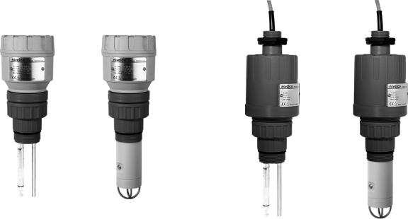
Two-wire compact analytical transmitters
Manufacturer:
NIVELCO Process Control Co.
H-1043 Budapest, Dugonics u. 11.
Phone: (36-1) 889-0100  Fax: (36-1) 889-0200 E-mail: sales@nivelco.com
  www.nivelco.com
BKI 11 ATEX 0012 X le00100a0600p_03 1 / 60
pHand ORP- |
Dissolved oxygen |
pHand ORP- |
Dissolved oxygen |
sensors and transmitters (compact type) |
sensors and transmitters (integrated type) |
||
2 / 60 le0010a0600p_03 BKI 11 ATEX 0012 X
TABLE OF CONTENTS |
|
|
1. INTRODUCTION.............................................................................................................................................................................................................................. |
5 |
|
1.1. |
APPLICATION ............................................................................................................................................................................................................................ |
5 |
1.2. |
OPERATION PRINCIPLE............................................................................................................................................................................................................... |
5 |
1.2.1. Characteristics of an ideal pH electrode .......................................................................................................................................................................................................... |
5 |
|
1.2.2. Characteristics of an ideal ORP electrode....................................................................................................................................................................................................... |
6 |
|
1.2.3. Characteristics of an ideal DO sensor ............................................................................................................................................................................................................. |
6 |
|
2. ORDER CODES............................................................................................................................................................................................................................... |
7 |
|
2.1. |
CONFIGURATIONS.................................................................................................................................................................................................................... |
11 |
3. TECHNICAL DATA........................................................................................................................................................................................................................ |
16 |
|
3.1. TECHNICAL DATA OF THE PH ELECTRODES (INCLUDING EX VERSIONS) FOR LP--INSTRUMENTS ................................................................................. |
18 |
|
3.2. TECHNICAL DATA OF THE ORP ELECTRODES (INCLUDING EX VERSIONS) FOR LR--INSTRUMENTS............................................................................. |
20 |
|
3.3. TECHNICAL DATA OF THE DO SENSORS (INCLUDING EX VERSIONS) FOR LD--INSTRUMENTS ..................................................................................... |
22 |
|
3.4. |
ACCESSORIES......................................................................................................................................................................................................................... |
22 |
4. MAINTENANCE AND REAPAIR................................................................................................................................................................................................... |
23 |
|
4.1. |
STORAGE ............................................................................................................................................................................................................................... |
23 |
4.2. PERIODIC SETTING, CALIBRATION AND VERIFICATION .................................................................................................................................................................. |
23 |
|
4.2.1. Periodic calibration of the pH electrode ......................................................................................................................................................................................................... |
24 |
|
4.2.2. Verification of the ORP electrode .................................................................................................................................................................................................................. |
25 |
|
4.2.3. Periodic calibration of the DO sensor ............................................................................................................................................................................................................ |
25 |
|
4.3. MAINTENANCE OF THE PH AND ORP ELECTRODES .................................................................................................................................................................... |
27 |
|
4.4. MAINTENANCE OF THE DO SENSOR .......................................................................................................................................................................................... |
29 |
|
4.5. |
SOFTWARE UPDATE................................................................................................................................................................................................................. |
29 |
5. INSTALLATION ............................................................................................................................................................................................................................. |
30 |
|
5.1. |
MOUNTING.............................................................................................................................................................................................................................. |
30 |
5.1.1. Installation of pH and ORP electrodes........................................................................................................................................................................................................... |
30 |
|
5.1.2. Installation of DO sensor ............................................................................................................................................................................................................................... |
31 |
|
5.1.3. Special application possibilities of the Integrated type instruments ............................................................................................................................................................... |
33 |
|
5.2. |
WIRING................................................................................................................................................................................................................................... |
34 |
5.2.1. Wiring of Compact instruments...................................................................................................................................................................................................................... |
34 |
|
5.2.2. Wiring of Integrated instruments.................................................................................................................................................................................................................... |
35 |
|
5.3. LOOP CURRENT CHECKING WITH HAND INSTRUMENT.................................................................................................................................................................. |
35 |
|
5.4. |
CONDITIONS OF EX APPLICATION .............................................................................................................................................................................................. |
35 |
|
|
BKI 11 ATEX 0012 X le00100a0600p_03 3 / 60 |
6. PROGRAMMING ........................................................................................................................................................................................................................... |
36 |
|
6.1. THE SAP-300 DISPLAY UNIT.................................................................................................................................................................................................... |
36 |
|
6.2. MEASURING WITH THE SAP-300 DISPLAY UNIT.......................................................................................................................................................................... |
37 |
|
6.3. PROGRAMMING WITH THE SAP-300 DISPLAY MODULE ............................................................................................................................................................... |
40 |
|
6.3.1. Components of the programming interface .................................................................................................................................................................................................... |
40 |
|
6.3.2. |
Menu structure................................................................................................................................................................................................................................................ |
41 |
6.4. PROGRAMMABLE FEATURES DESCRIPTION................................................................................................................................................................................. |
42 |
|
6.4.1. |
Basic measurement settings .......................................................................................................................................................................................................................... |
42 |
6.4.2. |
Analogue output ............................................................................................................................................................................................................................................. |
44 |
6.4.3. |
Relay output ................................................................................................................................................................................................................................................... |
45 |
6.4.4. |
Digital output................................................................................................................................................................................................................................................... |
47 |
6.4.5. |
Service functions ............................................................................................................................................................................................................................................ |
47 |
6.5. PH SENSOR CALIBRATION........................................................................................................................................................................................................ |
53 |
|
6.5.1. Editing one item of the calibration table.......................................................................................................................................................................................................... |
53 |
|
6.5.2. Adding an item to the calibration table ........................................................................................................................................................................................................... |
55 |
|
6.5.3. Deleting an element of the calibration table ................................................................................................................................................................................................... |
55 |
|
6.5.4. Reset the calibration table to default .............................................................................................................................................................................................................. |
55 |
|
6.5.5. |
Calibration procedure ..................................................................................................................................................................................................................................... |
55 |
6.6. |
DO SENSOR CALIBRATION ....................................................................................................................................................................................................... |
56 |
6.6.1. Calibration of saturated value (100%) ............................................................................................................................................................................................................ |
56 |
|
6.6.2. Calibration of Zero point (0%)......................................................................................................................................................................................................................... |
57 |
|
6.6.3. Calibration with referential DO instrument...................................................................................................................................................................................................... |
57 |
|
6.6.4. Reset the calibration table to default .............................................................................................................................................................................................................. |
57 |
|
6.6.5. |
Reset Timer.................................................................................................................................................................................................................................................... |
57 |
6.7. |
ERROR CODES ........................................................................................................................................................................................................................ |
58 |
4 / 60 le0010a0600p_03 BKI 11 ATEX 0012 X

Thank you for choosing a NIVELCO instrument.
We are sure that you will be satisfied throughout its use!
1. INTRODUCTION
1.1. APPLICATION
The AnaCONT compact transmitters, liquid analytical instruments are suitable for high precision measurement and transmission of acidity or alkalinity - pH (Hydrogen ion concentration) value -, reducing and oxidizing capability - ORP (Oxidation Reduction Potential) value -, or Dissolved Oxygen content of process water, wastewater, surface water, ground water and drinking water. These measurements can be widely used in industrial practice and could be of great relevance. In the field of environmental protection or sewage treatment, instruments like that are suitable for measuring the concentration of hazardous substances (chromium, cyanide). In chemicaland pharmaceutical industry, high precision measurement has utmost importance in the aspect of the technology (e.g. solvent feed), in many cases it is quality specification standard.
1.2. OPERATION PRINCIPLE
The intelligent signal processing of the electronics calculates the output signal from the voltage output values of the electrode and the temperature probe, and compensates it to 25°C. This value composes the basis of all output signals of the instrument.
1.2.1. Characteristics of an ideal pH electrode
The pH electrode immersed into the measured liquid measures a voltage value which is proportional to the hydrogen ion concentration of the liquid.
0mV output at neutral pH value (pH=7.00)
Positive voltage output in acidic liquids (pH<7)
Negative voltage output in alkaline liquids (pH>7)
Total measuring range is 0-14pH
-59.16mV/pH (Nernst potential) slope at 25 °C
The temperature dependency of the Nernst potential is -0.001984 mV / °C.
600 |
|
|
|
|
|
|
|
|
|
|
|
|
|
100° C (74.04 mV/pH) |
||||||||||||||||
500 |
|
|
|
|
|
|
|
|
|
|
|
|
|
|||||||||||||||||
400 |
|
|
|
|
|
|
|
|
|
|
|
|
|
25° C (59.16 mV/pH) |
||||||||||||||||
300 |
|
|
|
|
|
|
|
|
|
|
|
|
|
|
|
|
|
|
|
|
|
|
|
|
|
|
|
|
|
|
|
|
|
|
|
|
|
|
|
|
|
|
|
|
|
|
|
|
|
|
|
|
|
|
|
|
|
|
|
|
|
200 |
|
|
|
|
|
|
|
|
|
|
|
|
|
|
|
|
|
|
|
|
|
|
|
|
|
|
|
|
|
|
|
|
|
|
|
|
|
|
|
|
|
|
|
|
|
|
|
|
|
|
|
|
|
|
|
|
|
|
|
|
|
100 |
|
2 |
4 |
6 |
8 |
10 |
12 |
14 |
||||||||||||||||||||||
|
||||||||||||||||||||||||||||||
0 |
|
|
|
|
|
|
|
|
|
|
|
|
|
|
|
|
|
|
|
|
|
|
|
|
|
|
|
|
|
|
100 |
|
1 |
|
3 |
|
5 |
|
7 |
|
|
9 |
|
|
1 1 |
|
|
13 |
|
||||||||||||
|
|
|
|
|
|
|
|
|
|
|
|
|
|
|
|
|
|
|
|
|
|
|
|
|
|
|
|
|
|
|
200 |
|
|
|
|
|
|
|
|
|
|
|
|
|
|
|
|
|
|
|
|
|
|
|
|
|
|
|
|
|
|
300 |
|
|
|
|
|
|
|
|
|
|
|
|
|
|
|
|
|
|
|
|
|
|
|
|
|
|
|
|
|
|
|
|
|
|
|
|
|
|
|
|
|
|
|
|
|
|
|
|
|
|
|
|
|
|
|
|
|
|
|
|
|
400 |
|
|
|
|
|
|
|
|
|
|
|
|
|
|
|
|
|
|
|
|
|
|
|
|
|
|
|
|
|
|
500 |
|
|
|
|
|
|
|
|
|
|
|
|
|
0° C (54.20 mV/pH) |
||||||||||||||||
600 |
|
|
|
|
|
|
|
|
|
|
|
|
|
|
|
|
|
|
|
|
|
|
|
|
|
|
|
|
|
|
|
|
|
|
|
|
|
|
|
|
|
|
|
|
|
|
|
|
|
|
|
|
|
|
|
|
|
|
|
|
|
Because the pH electrodes in deed are not ideal (their properties depend on the design of the electrode, manufacturing tolerances and most of all the age of the electrode) the parameters differ from the given values above. To achieve reliable pH measurement and accuracy these electrodes must be calibrated from time to time. The time interval between two calibrations depends on the application conditions where the pH probes are used. Calibration of pH electrodes means offsetting the displayed value (7.00pH) when gauging neutral buffer solution, and adjusting the slope (pH/mV) by measuring buffer solutions with other pH value (usually with 4.00pH and 10.00pH value) by adjusting the displayed value to exact 4.00 and 10.00pH, respectively.
BKI 11 ATEX 0012 X le00100a0600p_03 5 / 60
1.2.2. Characteristics of an ideal ORP electrode
Negative voltage output in liquids with reduction potential,
Positive voltage output in liquids with oxidation potential,
Output voltage is equal to the redox potential (according to the Nernst equation)
pH independent measurement with certain types
To achieve reliable measurement and accuracy, these electrodes have to be thoroughly checked before installation and during usage from time to time. The time interval between two calibrations depends on the application and conditions where the ORP probes are used.
1.2.3. Characteristics of an ideal DO sensor
The dissolved oxygen level indicates the amount (in mg/l or ppm) of physically dissolved gas-form oxygen in liquid phase.
Oxygen-permeable membrane amperometric DC sensor wetted in the measurement medium gives output urrent proportional to the dissolved oxygen concentration of the medium.
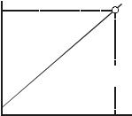
The ideal DO sensor has:
Izero=0,
Temperature independent output current
iair
Ouof tputhe t cuDO rren tsensor
izero
Slope = Output current of the
DO sensor/ppm oxygen
0 |
Dissolved oxygen (DO), ppm |
sat´n |
|
|
Real DO sensor gives off a minimal Izero≠0ppm current in case of 0 ppm dissolved oxygen concentration and its oxygen-permeable capability is temperaturedependent. Oxygen-permeable capability of the membrane is increasing according to the increase of the temperature, at 25 °C it can be 4%/°C. Temperature proportional correction is necessary for reliable measurement.
The DO sensors in deed are not ideal (their properties depend on the design of the electrode, manufacturing tolerances and most of all the age of the electrode), so the parameters differ from the given values above. To give reliable DO measurement and accuracy these electrodes must be calibrated from time to time. In case of DO sensors the calibration means that 0 ppm output value have to be set by offsetting in an oxygen-free solution. For DO measurement of other mediums (for example dry air 20.95%@25°C or oxygen-saturated water) adjustment of slope (nA/ppm) has to done accurately according to the properties of these mediums.
6 / 60 le0010a0600p_03 BKI 11 ATEX 0012 X

2. ORDER CODES
Not all combinations possible!
AnaCONT instruments:
|
AnaCONT L |
|
|
|
|
|
|
|
- |
|
|
|
|
|
|
|
|
|
- |
|
|
* |
|
|
|
|
|
|
|
|
|
|
|
|
|
|
|
|
|
|
|
|
|
|
|
|
|
|
|
|
|
|
|
|
|
|
|
|
|
|
|
|
|
|
|
|
|
|
|
|
|
|
|
|
TYPE |
CODE |
|
FUNCTION |
CODE |
|
HOUSING |
CODE |
|
PROBE*** |
|||
|
|
|
|
|
|
|
|
|
|
|
|
|
Transmitter |
E |
|
pH |
P |
|
Plastic |
1 |
|
|
|
|
|
Transmitter + |
G |
|
ORP |
R |
|
Aluminium |
2 |
|
|
|
|
|
display |
|
|
|
|
|
|
||||||
|
|
|
|
|
|
|
|
|
|
|
|
|
Integrated |
P |
|
DO |
D |
|
|
|
|
|
|
|
|
|
|
|
|
|
|
|
|
|
|
|
|
|
PH PROBE |
CODE |
4xpher112seph |
1 |
4xphed112seph |
2 |
4xphex112seph |
3 |
4xpheph314sph |
4 |
4xphe1120seph |
5 |
4xphes112seph |
6 |
4xphep112seph |
7 |
4xphekl112seph |
8 |
ORP PROBE |
CODE |
4xorrherpseor |
1 |
4xorrhexpseor |
2 |
4xorrheptseor |
3 |
4xorrhespseor |
4 |
4xorrheppseor |
5 |
4xorrheklseor |
6 |
*The order code of an Ex version should end in “Ex”!
**Approval is pending
***Probe selection is detailed in 3rd chapter.
DO PROBE |
CODE |
4x085g0023ydo / 20ppm |
1 |
4x085g0022ydo / 10ppm |
2 |
PROC. CONN. / |
CODE |
|
MATERIAL |
||
|
||
BSP 1½ “ / PP |
1 |
|
BSP 1½ “ / PVDF |
2 |
|
|
|
|
NPT 1½ “ / PP |
4 |
|
NPT 1½ “ / PVDF |
5 |
OUTPUT |
CODE |
|
|
|
|
4 |
… 20 mA |
2 |
4 |
… 20 mA / HART |
4 |
|
|
|
4 |
… 20 mA / Ex |
6** |
4 |
… 20 mA / HART / Ex |
8** |
4 |
… 20 mA / Relay |
R |
4 |
… 20 mA / HART / Realy |
H |
BKI 11 ATEX 0012 X le00100a0600p_03 7 / 60
The extension unit, adjustment unit and the sensor housing can be ordered to every analytical device, apart from the type of the electrode, measurement principal and measured quantity. Sensor protection tube is available only for LP--, or LR-- instruments.
|
|
EXTENSIONS |
|
L |
A |
|
|
– |
|
|
|
|
|
|
|
|
|
|
|
|
– |
0 |
|
|
|
|
|
|
|
|
|
|
|
|
|
|
|
|
|
|
|
|
|
|
|
|
|
|
|
|
|
|
|
|
|
|
|
|
|
|
|
|
|
|
|||
|
|
|
|
|
|
|
|
|
|
|
|
|
|
|
|
|
|
|
|
|
|
|
|
|
|
|
|||||||
|
|
TYPE |
C |
ODE |
|
MATERIAL |
CODE |
|
|
CODE |
|
|
LENGTH (L) |
|
CODE |
|
|
|
|
|
|||||||||||||
|
|
Pipe |
R |
|
PP |
1 |
|
|
|
|
0 |
|
|
|
0 m |
|
0 m |
|
0 |
|
|
|
|
|
|||||||||
|
|
Cable |
K |
|
PVDF |
2 |
|
|
|
|
1 |
|
|
|
1 m |
|
0.1 m |
|
1 |
|
|
|
|
|
|||||||||
|
|
Suspended pipe |
F |
|
|
|
|
|
|
|
|
|
|
|
2 |
|
|
|
2 m |
|
0.2 m |
|
2 |
|
|
|
|
|
|||||
|
|
|
|
|
|
|
|
|
|
|
|
|
|
|
|
|
3 |
|
|
|
3 m |
|
0.3 m |
|
3 |
|
|
|
|
|
|||
|
|
|
|
|
|
|
|
|
|
|
|
|
|
|
|
|
4 |
|
|
|
4 m |
|
0.4 m |
|
4 |
|
|
|
|
|
|||
|
|
|
|
|
|
|
|
|
|
|
|
|
|
|
|
|
5 |
|
|
|
5 m |
|
0.5 m |
|
5 |
|
|
|
|
|
|||
|
|
|
|
|
|
|
|
|
|
|
|
|
|
|
|
|
6 |
|
|
|
6 m |
|
0.6 m |
|
6 |
|
|
|
|
|
|||
|
|
|
|
|
|
|
|
|
|
|
|
|
|
|
|
|
7 |
|
|
|
7 m |
|
0.7 m |
|
7 |
|
|
|
|
|
|||
|
|
|
|
|
|
|
|
|
|
|
|
|
|
|
|
|
8 |
|
|
|
8 m |
|
0.8 m |
|
8 |
|
|
|
|
|
|||
|
|
|
|
|
|
|
|
|
|
|
|
|
|
|
|
|
9 |
|
|
|
9 m |
|
09 m |
|
9 |
|
|
|
|
|
|||
|
|
|
|
|
|
|
|
|
|
|
|
|
|
|
|
|
|
|
A |
|
10 m |
|
|
|
|
|
|
|
|
|
|
||
|
|
|
|
|
|
|
|
|
|
|
|
|
|
||||||||||||||||||||
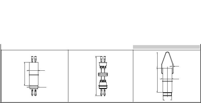
|
PIPE EXTENSION: LAR--0 |
|
|
|
CABLE EXTENSION: LAK--0 |
|
|
|
SUSPENDED PIPE EXTENSION: LAF--0 |
|
|
||||||||||||||||||||||
|
|
|
|
|
|
|
|
|
|
|
|
|
|
|
|
|
|
|
|
|
|
|
|
|
|
|
|
|
|
|
|
|
|
3 |
Ø63 |
|
m |
m |
|
- |
||
2 |
0 |
|
1 |
||
, |
||
0 |
- |
|
= |
1 |
|
L |
= |
|
|
L |
BSP2"
110 |
|
|
Ø3 |
- 3m |
Ø63 |
L = 0,2 |
|
|
BSP2" |
8 / 60 le0010a0600p_03 BKI 11 ATEX 0012 X

SLIDING SLEEVE: L A A – |
1 0 |
|
|
|
– 0 |
|||
|
|
|
|
|
|
|
|
|
|
|
|
|
|
|
|
|
|
|
|
|
CODE |
|
|
|
|
|
|
DN80 PN16 / PP |
2 |
|
|
|
|
||
|
DN100 PN16 / PP |
3 |
|
|
|
|
||
|
DN125 PN16 / PP |
4 |
|
|
|
|
||
|
|
|
|
|
|
|
|
|
|
DN150 PN16 / PP |
5 |
|
|
|
|
||
|
DN200 PN16 / PP |
6 |
|
|
|
|
||
|
Console mounting bracket, 200 mm |
|
K |
|
|
|
|
|
|
|
|
|
|
|
|
|
|
|
Mounting bracket, 200 mm |
|
T |
|
|
|
|
|
SLIDING SLEEVE WITH FLANGE: LAA-10-0
63
DN80 - DN200 |
pH/ORP DO
CONSOLE MOUNTING BRACKET: |
MOUNTING BRACKET: LAA-10T-0 |
|||
|
LAA-10K-0 |
|
|
|
|
|
70 |
|
|
|
|
200 mm |
|
|
|
2 |
|
|
|
|
|
|
2 |
|
|
|
1 |
|
|
|
|
Ø |
|
|
|
150 |
|
80 |
110 |
|
A |
|
|
|
|
Ø |
|
|
|
DO |
pH/ORP |
|
|
|
|
FOR EXTENSION TYPE |
FOR BASIC TYPE |
||
|
ØA =63.5MM |
ØA =70.5MM |
||
|
BKI 11 ATEX 0012 X le00100a0600p_03 9 / 60 |
|||

MATERIAL |
SENSOR PROTECTION TUBE: L A P – 1 |
PP |
2 PVDF
SIZE |
1 |
1½” |
0 – 0 |
|
2 |
2” |
|
|
|
|
|
|
PROTECTION TUBE 1½”: LAP-10-0 |
PROTECTION TUBE 2”: LAP-20-0 |
FOR EXTENSION TYPE |
FOR BASIC TYPE |
|
BSP1 1/2" |
BSP1 1/2" |
|
|
BSP 2" |
|
112 |
130 |
|
|
Ø51 |
Ø51 |
55 |
Sensor protection tube is available only for LP--, or LR-- instruments |
|
BKI 11 ATEX 0012 X le00100a0600p_03 10 / 60