

Practical Plastic Surgery
.pdf322 Practical Plastic Surgery
|
|
Table 52.4. Free flaps used for leg reconstruction |
||
|
|
|
|
|
|
|
Flap |
Pedicle |
Comments |
|
|
Gracilis |
Medial femoral |
Good for small areas; round muscle |
|
|
|
circumflex a. |
may be and teased out flattened |
|
|
Rectus abdominis |
Deep inferior |
Can be used with skin paddle |
|
|
muscle |
epigastric a. |
Can reach knee if extended |
|
|
|
|
approach used |
|
|
Latissimus dorsi |
Thoracodorsal a. |
Large |
|
|
Fibula |
Peroneal a. |
Good source of vascularized bone |
|
|
Tensor fascia lata |
Transverse branch |
Good for large defects |
|
|
|
of lateral femoral |
Lateral femoral cutaneous may allow |
|
|
|
circumflex a. |
sensory reinnervation |
|
|
defects may be covered using a turnover flap of the anterior tibialis muscle. Again, |
||
|
|
fasciocutaneous flaps may also be useful. |
|
|
|
|
Distal Tibia |
|
|
|
|
Free flaps are commonly used in the distal fibia. The dorsalis pedis fasciocutaneous |
||
|
|
flap can cover relatively large defects about the distal tibia. The lateral supramalleolar |
||
|
|
flap and the extensor brevis flap may be used to cover somewhat smaller defects. |
||
|
|
Distally-based fasciocutaneous flaps may also be used. |
||
|
|
Foot |
|
|
52 |
|
|
||
|
|
Extensive wounds of the foot may require free-tissue transfer for closure (Table |
||
|
|
52.5). The sural artery flap may be of use for wounds about the ankle and heel. |
||
|
|
Plantar defects in ambulatory patients must be reconstructed with tissue that is |
||
|
|
durable enough to bear weight and shear forces. Underlying bony abnormalities |
||
|
|
that might create pressure points should be corrected. |
||
|
|
Replantation may be considered when there is a single simple, transection with- |
||
|
|
out associated blunt injury and the warm ischemia time is less than 6 hours. It is |
||
|
|
most suited to healthy, young individuals without significant comorbidities. Lower |
||
|
|
extremity replantation is relatively rare due to several factors including: the likeli- |
||
|
|
hood of significant concomitant injury; the difficulty in achieving useful neurologic |
||
|
|
function; and the widespread acceptance and utility of prosthetics. |
||
|
|
Conclusions |
|
|
|
|
Attempts at lower extremity reconstruction should be geared toward providing |
||
|
|
the most functional outcome in light of the extent of injury and comorbid factors. |
||
|
|
In some cases, amputation may provide the quickest road to meaningful recovery. |
||
|
|
Pearls and Pitfalls |
|
|
|
|
Essential principles for lower extremity wound management include: prompt |
||
|
|
evaluation, debridement of nonviable tissue, patience (awaiting infection resolution |
||
|
|
and signs of granulation) and prompt coverage when ready. Utilization of negative |
||
|
|
pressure therapy often temporizes the situation, reducing the need for urgent cover- |
||
|
|
age and often down-staging the wound allowing for simpler closure method. |
||
|
|
Flaps are required for bone and tendon coverage of the lower extremity. Usually, |
||
|
|
a local flap (muscle or fasciocutaneous) can be designed to cover small defects (<10 |
||
|
|
|
|
|

Lower Extremity Reconstruction |
323 |
|
|
|
|
Table 52.5. Free flaps used for coverage of the foot |
|
||||
|
|
|
|
|
|
Type |
Flap |
Pedicle |
Comments |
|
|
Cutaneous |
Groin |
Superficial iliac |
Large flap can be raised |
|
|
|
|
circumflex a. |
|
|
|
|
Scapular or |
Circumflex a. |
Thick flap |
|
|
|
parascapular |
of the scapula |
|
|
|
Fasciocutaneous |
Radial |
Radial a. |
Widely used |
|
|
|
|
|
Can be re-innervated |
|
|
|
|
|
or combined with bone |
|
|
|
Lateral arm |
Branches from |
Small, thin flap |
|
|
|
|
brachialis |
|
|
|
|
|
profunda a. |
|
|
|
Muscle |
Latissimus |
Thoracodorsal a. |
Large, bulky flap |
|
|
|
dorsi |
|
Can be myocutaneous |
|
|
|
Gracilis |
Medial femoral |
May be myocutaneous |
|
|
|
|
circumflex a. |
Easy dissection |
|
|
|
Anterior |
Branch of |
Difficult dissection |
|
|
|
serratus |
thoracodorsal a. |
|
|
|
Osteocutaneous |
Iliac crest |
Deep and |
Double pedicle |
|
|
|
|
superficial iliac |
Useful for calcaneal |
|
|
|
|
circumflex a. |
reconstruction |
|
|
|
Fibula |
Peroneal a. |
Useful for metatarsal loss |
|
|
|
|
|
Can include soleus |
|
|
|
|
|
52 |
||
|
|
|
|
|
|
cm2) of the foot and ankle; the additional soft tissue and flap donor site defects can |
|
||||
be skin grafted. Larger wounds require more distant tissue transfer. |
|
||||
Suggested Reading
1.Arnez ZM. Immediate reconstruction of the lower extremity—an update. Clin Plast Surg 1991; 18(3):449.
2.Arnold PG, Irons GB. Lower-extremity muscle flaps. Orthop Clin North Am 1984; 15(3):441.
3.Attinger C. Soft-tissue coverage for lower-extremity trauma. Orthop Clin North Am 1995; 26(2):295.
4.Byrd HS, Cierny IIIrd G, Tebbetts JB. The management of open tibial fractures with associated soft-tissue loss: External pin fixation with early flap coverage. Plast Reconstr Surg 1981; 68(1):73.
5.Heller L, Levin LS. Lower extremity microsurgical reconstruction. Plast Reconstr Surg 2001; 108(4):1029.
6.Johansen K, Daines M, Howley T et al. Objective criteria accurately predict amputation following lower extremity trauma. J Trauma 1990; 30:568.
7.Park S, Han SH, Lee TJ. Algorithm for recipient vessel selection in free tissue transfer to the lower extremity. Plast Reconstr Surg 1999; 103(7):1937-48.
8.Zenn MR, Levin LS. Microvascular reconstruction of the lower extremity. Semin Surg Oncol 2000; 19(3):272.

Chapter 53
Basic Dental Concepts
Mark Sisco and Jeffrey A. Hammoudeh
Introduction
Dental anatomy, physiology and occlusion are important aspects of plastic and reconstructive surgery. They allow clinicians to communicate consistently and are the underpinning of surgical intervention for many pediatric craniofacial syndromes.
Nomenclature
The 20 deciduous (primary) teeth, starting at the midline, are named central incisor, lateral incisor, canine, first molar and second molar. The 32 permanent teeth, starting at the midline, are named central incisor, lateral incisor, canine (cuspid), first premolar (bicuspid), second premolar (bicuspid), and first, second and third molars.
The Universal system is most commonly used to describe the permanent teeth. The maxillary teeth are numbered starting at the upper right third molar (no. 1) and ending at the left upper third molar (no. 16). The mandibular teeth are numbered in the opposite direction, from the left lower third molar (no. 17) to the right lower third molar (no. 32).
1 2 3 4 5 6 7 8 | 9 10 11 12 13 14 15 16 32 31 30 29 28 27 26 25|24 23 22 21 20 19 18 17
The deciduous teeth are denoted by letters in the same order, from A to T. A through J represent the maxillary teeth, starting at the upper right second molar. K through T represent the mandibular teeth, starting at the lower left second molar.
A |
B C D |
E | F G H I J |
T |
S R Q P | O N M L K |
|
Anatomy
The normal tooth is comprised of the crown and the root. The majority of the tooth consists of dentin. The crown, which is exposed to the oral cavity, is covered by a layer of enamel. The root, which interfaces with the alveolar socket, is covered by cementum. The pulp chamber and canal are found in the middle of the crown and root, respectively. The pulp tissue supplies the tooth with its sensory and blood supply.
The maxillary teeth are supplied by the posterior, middle and anterior superior alveolar nerves, which are branches of the maxillary division of the trigeminal nerve (CN V). The latter two superior alveolar nerves are supplied by CN V via the infraorbital nerve. The mandibular teeth are supplied by the inferior alveolar nerve from the mandibular division of the trigeminal nerve.
Practical Plastic Surgery, edited by Zol B. Kryger and Mark Sisco. ©2007 Landes Bioscience.

Basic Dental Concepts |
325 |
|
|
|
|
Table 53.1. Age of eruption of the deciduous teeth
Age (Months) |
Deciduous Teeth |
6-7 |
Central incisors |
7-9 |
Lateral incisors |
12-14 |
First primary molars |
16-18 |
Canines |
20-24 |
Second primary molars |
Pattern of Eruption
The deciduous teeth begin to erupt at six months of age. Maxillary and mandibular teeth tend to erupt at the same times (Table 53.1). The primary dentition eventually exfoliates and is replaced by the permanent detention in a predictable sequence (Table 53.2).
Pathologic Descriptions
Occlusion describes the relationship, or fit, between the upper and lower teeth when in contact. The occlusal plane is the curvilinear plane along which the teeth erupt and meet each other.
Overbite refers to the amount of vertical overlap between the maxillary and mandibular incisal edges when in occlusion. Anterior open bite describes a situation where these incisal edges do not overlap, resulting in a negative overbite.
Overjet refers to the forward projection of the upper incisors beyond the lower incisors when the teeth are in occlusion.
Crossbite exists when there is an abnormal buccolingual relationship among 53 the upper and lower molars. In normal or neutral occlusion, the buccal cusps of
the maxillary teeth overlap those of the mandibular teeth. Buccal crossbite occurs when the entire maxillary tooth is buccal to the mandibular tooth. Lingual crossbite occurs when the buccal cusps of the mandibular teeth overlap the maxillary teeth.
Table 53.2. Age of eruption of the permanent teeth
Age (Years) |
Permanent Teeth |
6 |
Mandbular first molar followed by maxillary first molar |
6 |
Mandibular central incisor |
7 |
Mandibular lateral incisors |
7 |
Maxillary central incisors |
8 |
Maxillary lateral incisors |
10 |
First maxillary and mandibular premolars |
10 |
Mandibular canines |
11 |
Second maxillary and mandibular premolars |
11 |
Maxillary canines |
12 |
Second molars |
17 |
Third molars |

326 |
Practical Plastic Surgery |
Common Tooth Injuries
Subluxation refers to intrusion and extrusion. Most intruded deciduous teeth require no treatment as they will erupt spontaneously. However, if the intruded tooth fails to resorb or erupt in an appropriate timeframe, it must be extracted to allow for eruption of the permanent tooth bud. Intruded permanent teeth are electively repositioned by the orthodontist.
Extruded primary teeth are usually not replanted; the patient should instead be referred to an orthodontist for fabrication of a space maintainer. An attempt may be made to replant an extruded permanent tooth within 1-2 hours of injury. Prior to any attempt, the socket should be irrigated. After one hour, any clot or granulation in the socket should be aggressively debrided. After two hours, replantation will generally fail.
Tooth fractures that involve the crown are typically treated by the endodontist. Fractures involving the root usually require removal of the tooth.
Pearls and Pitfalls
The importance of accurate identification of teeth cannot be overstated. Learn the standard nomenclature. If you have any doubt about which tooth number to use, refer to the proper name, such as “right mandibular second molar.” You do not want to write the wrong number in a progress note or extract the wrong tooth in the line of a fracture.
It is important to treat extruded primary teeth with a space maintainer, which is fabricated by an orthodontist or pediatric dentist. Loss of primary teeth may lead to shifting of the remaining teeth. The resultant loss of arch space can ultimately cause
53 crowding and malocclusion of the permanent dentition.
Suggested Reading
1.Bischoff RJ, Simon WJ. The occluding system of the teeth. A review of the occluding system of the mouth—from nomenclature to malocclusions. Dent Assist 1975; 44(1):17.
2.Goodman P. A universal system for identifying permanent and primary teeth. J Dent Child 1967; 34(5):312.
3.Lunt RC, Law DB. A review of the chronology of eruption of deciduous teeth. J Am Dent Assoc 1974; 89(4):872.
4.Natiella JR, Armitage JE, Greene GW. The replantation and transplantation of teeth. A review: Oral Surg Oral Med Oral Pathol 1970; 29(3):397.
5.Wilson KS, Hohmann A. Dental anatomy and occlusion. Otolaryngol Clin North Am 1976; 9(2):425.

Chapter 54
Cephalometrics
Matthew Jacobsen and Jeffrey A. Hammoudeh
Introduction
The analysis of a patient with a skeletal deformity can be complex. However, there are many diagnostic tools available that help the surgeon understand the etiology of the deformity, including the history and physical, radiographic exams, videocephalometric analysis and cast dental models. The integration of this information provides the appropriate diagnosis and guides treatment. The goal of this chapter is to provide the clinician with the basic working principles for detecting and diagnosing maxillofacial deformities.
Clinical Exam—Dental Classification
Terminology:
•Open bite—the tips of the incisors are not directly opposed
•Overbite—the vertical distance between the tips of the incisors
•Overjet—the horizontal distance between the tips of the incisors
•Neutral occlusion (Class I)—the maxillary first molar mesiobuccal cusp fits in the buccal groove of the mandibular first molar
•Distal occlusion (Class II)—the maxillary first molar mesiobuccal cusp is anterior to the buccal groove of the mandibular first molar
•Mesial occlusion (Class III)—the maxillary first molar mesiobuccal cusp is posterior to the buccal groove of the mandibular first molar
The frontal smiling exam documents symmetry of the smile as well as the amount of maxillary and mandibular dentition and gingival exposure. The normal amount of exposed gingiva during smiling is 1-2 mm. Particular attention should be paid to the amount of maxillary tooth show from central incisor to canines. In addition, during the intraoral exam the clinician should look for an anterior or posterior open bite. It is important to determine the maxillary and mandibular midpoints in order to understand if the maxilla and mandible are coincident with the facial midline or if there is a deviation of one or both. Finally the intraoral exam is used to assess for the presence of overjet, overbite and malocclusion.
Facial Relationships
Aside from the standard history and physical, the clinical exam incorporates subjective numerical data. With the patient seated at eye level across from you, evaluate the face into its proportions of facial thirds. Facial proportions are be considered within the context of the following normal relationships:
•The intercanthal width is roughly equal to the alar base width.
•The lower eyelid rests at or above the most inferior position of the iris. Measure any scleral show as it may be a sign of exophthalmos or infraorbital hypoplasia.
Practical Plastic Surgery, edited by Zol B. Kryger and Mark Sisco. ©2007 Landes Bioscience.

328 |
Practical Plastic Surgery |
•The width of the nasal dorsum is half the intercanthal width.
•Facial midline, nasal tip, maxillary and mandibular midlines, and chin point are in line.
•Upper face height (glabella to subnasale) should be equal to lower face height (subnasale to menton).
Inspect for symmetry and size of the forehead, orbits, eyes, ears and nose. Useful measurements include:
•Interpupillary width: normal is 65 mm
•Intercanthal width: normal is 32 mm for whites and 35 mm for African Americans
•Upper lip length: normal is 22 mm for males and 20 mm for females. Measured from subnasale to upper lip stomion.
•Upper tooth to lip relationship: 2.5 mm of incisal edge lips the lips relaxed
•Lower lip length: normal is 42 mm for males, 38 mm for females. Measured from lower lip stomion to menton.
At the end of the physical exam, take high quality digital photographs. These pho-
tos will be crucial to videocephalometric predictions, correlation with model surgery, and will be referred to intraoperatively. The following photos are recommended:
•Frontal photograph relaxed
•Frontal photograph smiling
•Lateral profile—right and left
•45˚ oblique
•Intraoral—central, right, left
The fabrication of dental casts aids in diagnosis as well as treatment. For ex-
ample, in orthognathic surgery it is essential to fabricate surgical splints. The casts must be properly mounted using the facebow, bite record and articulator.
54 The orthognathic workup and cephalometric analysis are important since they determine many of the surgical movements. A key point to an accurate workup is the careful positioning of the mandible in centric relation rather than in centric occlusion during the bite registration. Centric relation denotes position of mandible where the condyles are in the most superior, posterior position in the mandibular fossa. Centric occlusion is the position with maximal intercuspation of the teeth. During surgery, the mandible is positioned in centric relation as this depicts the skeletal defect and allows for a reproducible anatomic position.
Radiographic Analysis
After the clinical exam is completed, radiographic analysis helps to further define the nature of the patient’s maxillofacial deformity. The Panorex, lateral cephalogram and AP cephalogram are used. The Panorex is inspected for pathology of the sinus, joints, mandible, maxilla and dentition. Examine the Panorex closely for condylar morphology and position. The Ramus Condyle Unit is measured to determine if there are any asymmetries in condylar growth. This may be indicative of conditions such as idiopathic condylar resorption or condylar hyperplasia. The lateral and AP cephalograms are the two principle radiographs of othognathic surgery and cephalometric analysis. Classical cephalometric analysis required tracing the cephalometric film by hand. This allowed for identification of the hard and soft tissue landmarks used in the cephalometric analysis. Digital radiographs and computer cephalometric analysis are replacing traditional radiographs and hand tracings. Using a computerized tracing

Cephalometrics |
329 |
program, the surgeon selects several landmarks on the digitized lateral cephalogram. The computer then produces the cephalometric measurements and the digital tracing.
The relationship between the cranial base, nasomaxillary complex, mandible and maxillomandibular dentition is determined by the resulting angular and linear measurements. Notably, the surgeon may measure the distance from sella to posterior nasal spine (PNS). This value determines the position of the posterior maxilla in relation to the cranial base. The normal value is between 45-50 mm.
Cephalometric Analysis
The cephalometric analysis is a valuable tool that will assist the clinician with the diagnosis of a facial deformity. The diagnosis and treatment plan are determined during the clinical and cephalometric analysis. There are a variety of cephalometric analyses in clinical practice; the Singer and Harvard methods are most commonly used. Normal values for cephalometric measurements in adults are listed in Table 54.1.
Important cephalometric measurements include the following:
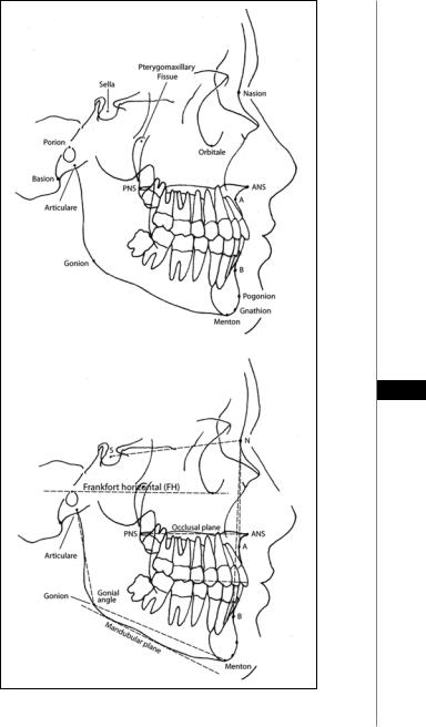
1.Porion: midpoint of upper contour of the external auditory canal
2.Sella: midpoint of the sella turcica
3.Orbitale: most inferior point along the bony orbit
4.Pterygomaxillary fissure: most superior posterior point of the pterygomaxillary fissure
5.Nasion: most anterior point of the frontonasal suture
6.Basion: Most inferior anterior point of the foramen magnum
7.Anterior nasal spine (ANS): most anterior point of the anterior nasal spine
8.Posterior nasal spine (PNS): most posterior point of the anterior nasal spine
9.A point: most posterior point along the bony premaxilla between ANS and 54 maxillary incisor
Table 54.1. Cephalometric measurements for adults (in mm)
Parameter |
Male |
Female |
Maxillary length |
114 4) |
105 (3) |
Mandibular length |
127 (5) |
119 (4) |
Total facial height |
137 (8) |
123 (5) |
Upper face height |
80 (6) |
55 (2) |
Lower face height |
80 (6) |
69 (5) |
Ethmoid point—PNS |
55 (4) |
50 (3) |
Sella—PNS |
56 (4) |
51 (3) |
Posterior face height |
88 (6) |
79 (4) |
Palatal plane—Menton |
76 (6) |
67 (4) |
Palatal plane—upper molar |
28 (3) |
25 (2) |
Palatal plane—upper incisor |
33 (3) |
30 (3) |
PNS—ANS |
62 (4) |
57 (4) |
Mandibular plane—lower incisor |
49 (3) |
42 (3) |
Manibular plane—lower molar |
38 (3) |
33 (3) |
|
|
|

330 |
Practical Plastic Surgery |
10.B point: most posterior point along the bony contour of the mandible between mandibular incisor and pogonion
11.Pogonion: most anterior point along the contour of the bony chin
12.Menton: most inferior point along the mandibular symphysis
13.Gnathion: point along bony chin between menton and pogonion
14.Gonion: angle of the mandible at the intersection of the tangents drawn from the posterior ramus border and the lower ramus
15.Articulare: point of intersection between the cranial base and posterior ramus
16.Condylion: most superior posterior point of the bony condyle Important cephalometric planes and angles include the following:
1.Sella-Nasion-A point: SNA
2.Sella-Nasion-B point: SNB
3.A point-Nasion-B point: ANB
4.Frankfort horizontal (FH) plane: Pogonion—Orbitale
5.Palatal plane: ANS-PNS
6.Occlusal plane: plane from mesial cusp of maxillary molar through point bisecting overbite
7.Mandibular plane: tangent along lower border of mandible
8.Gonial angle: Articulare-Gonion-Menton
SNA and SNB provide an assessment of the maxillary and mandibular relationship to the cranial base. However, in order to utilize SN as the normal inclination of the anterior cranial base, the surgeon must first normalize the actual SN position to the normal SN-FH of 6 degrees. In most patients, the sella turcica is normally positioned and thus the sella to Frankfort angle is normal. However, in patients with craniofacial deformities, congenital syndromes, or sequences, it is imperative to identify the relationship of sella-to-FH. Altering the normal position of sella will, by
54default, alter the SNA and SNB. In order to assess the true SNA/SNB one must determine the SN-FH correction.
1.First measure the SN-Frankfurt angle (normal is 6˚)
2.If the SN-F angle is abnormally acute due to a shallow SN plane, the measured SNA and SNB will be too obtuse. Therefore, we must subtract the
difference ([SN-FHactual-SN-FHnormal]) to generate the “corrected” SNA and SNB.
3.If the SN-F angle is abnormally obtuse due to a steep SN plane, the measured SNA and SNB will be too acute. Therefore, one must add the difference ([SN-FHactual-SN-FHnormal]) to generate the “corrected” SNA and SNB.
PA Cephalogram
The PA cephalogram illustrates transverse and vertical skeletal relationships and evaluates facial symmetry. The first step in analyzing the PA film is to analyze the transverse dimension using a J point analysis. A horizontal measurement is made from the lateral aspects of the maxilla at the level of the pyriform rims. Similarly, a horizontal measurement is made from antegonial notch form right to left. The difference between these two values is used to identify an excessively narrow maxilla or enlarged mandible. The normal J point value is between 20 and 23 mm. Next, the PA cephalogram is drawn on tracing paper. Horizontal lines are drawn at the infraorbital rim, pyriform rim, occlusal plane and gonial angle. These marks are compared to a vertical midline mark in order to determine symmetry and cant of the orbits, zygomas, maxilla and mandible.
Cephalometrics |
331 |
54
Figure 54.1. Common cephalometric points and their relationships.