

Справочные данные / Function diagrams DC Master (p.219-356)
.pdfs
SIMOREG DC-MASTER |
Operating Instructions |
|
|
6RA70 Series |
|
Microprocessor-Based Converters from 6kW to 2500kW for Variable-Speed DC Drives
Edition 13 |
Order-No.: 6RX1700-0AD76 |
05.2007 |
Function diagrams |
|
8 |
Function diagrams |
|
General |
Page |
|
|
Key to symbols ................................................................................................................ |
....... 8-5 |
Basic functions |
|
|
G100 |
Overview................................................................................................................................. |
8-6 |
G101 |
Hardware configuration .................................................................................................... |
...... 8-7 |
Inputs and outputs |
|
|
G110 |
Binary inputs terminals 36 to 39 (CUD1)................................................................................ |
8-8 |
G111 |
Binary inputs terminals 40 to 43 (CUD2)................................................................................ |
8-9 |
G112 |
Binary outputs terminals 46/47 and 48/54 (CUD1) .............................................................. |
8-10 |
|
Binary outputs terminals 50/51 and 52/53 (CUD2) .............................................................. |
8-10 |
G113 |
Analog inputs terminals 4/5, 6/7 (CUD1), and 103/104 (power interface) ........................... |
8-11 |
G114 |
Analog inputs terminals 8/9 and 10/11 (CUD2).................................................................... |
8-12 |
G115 |
Analog outputs terminals 12/13, 14/15, and 16/17 (CUD1) ................................................. |
8-13 |
G116 |
Analog outputs terminals 18/19 and 20/21 (CUD2) ............................................................. |
8-14 |
G117 |
E-Stop, Relay output line contactor (power interface).......................................................... |
8-15 |
Setpoint generation |
|
|
G120 |
Fixed values.......................................................................................................................... |
8-16 |
|
Fixed control bits............................................................................................................ |
....... 8-16 |
|
Constant fixed values and control bits.................................................................................. |
8-16 |
G121 |
Connector and binector displays .......................................................................................... |
8-17 |
G124 |
Connector selector switch ................................................................................................. |
... 8-18 |
G125 |
Evaluation of a 4-step master switch.................................................................................... |
8-19 |
G126 |
Motorized potentiometer................................................................................................... |
.... 8-20 |
G127 |
Fixed setpoint ....................................................................................................................... |
8-21 |
G128 |
Oscillation / square-wave generator..................................................................................... |
8-22 |
G129 |
Inching setpoint..................................................................................................................... |
8-23 |
G130 |
Crawling setpoint / terminal 37 ........................................................................................... |
.. 8-24 |
G135 |
Setpoint processing ....................................................................................................... |
....... 8-25 |
G136 |
Ramp-function generator (1) ............................................................................................... |
. 8-26 |
G137 |
Ramp-function generator (2) ............................................................................................... |
. 8-27 |
Internal control |
|
|
G140 |
Brake control......................................................................................................................... |
8-28 |
Actual speed value |
|
|
G145 |
Pulse generator evaluation................................................................................................ |
... 8-29 |
Controllers |
|
|
G150 |
Starting pulse - speed controller......................................................................................... |
.. 8-30 |
G151 |
Speed controller (1) ...................................................................................................... |
........ 8-31 |
G152 |
Speed controller (2) ..................................................................................................... |
......... 8-32 |
G153 |
Friction compensation ..................................................................................................... |
..... 8-33 |
|
Compensation of moment of inertia (dv/dt injection)............................................................ |
8-33 |
G160 |
Torque limitation, speed limit controller................................................................................ |
8-34 |
G161 |
Current limitation................................................................................................................... |
8-35 |
G162 |
Closed-loop armature current control................................................................................... |
8-36 |
G163 |
Auto-reversing stage, armature gating unit .......................................................................... |
8-37 |
G165 |
Closed-loop EMF control ................................................................................................... |
... 8-38 |
G166 |
Closed-loop field current control, field gating unit ................................................................ |
8-39 |
G167 |
Field current monitoring.................................................................................................. |
...... 8-40 |
SIEMENS AG 6RX1700-0AD76 |
8-1 |
SIMOREG DC-MASTER Operating Instructions |
|
Function diagrams |
05.2007 |
|
|
|
Page |
Serial interfaces |
|
|
G169 |
Serial interfaces: connector-type converters ........................................................................ |
8-41 |
G170 |
USS interface 1 (PMU) ......................................................................................................... |
8-42 |
G171 |
USS interface 2 (CUD1) ....................................................................................................... |
8-43 |
G172 |
USS interface 3 (CUD2) ....................................................................................................... |
8-44 |
G173 |
Peer-to-peer interface 2 (CUD1)........................................................................................... |
8-45 |
G174 |
Peer-to-peer interface 3 (CUD2)........................................................................................... |
8-46 |
Program structure |
|
|
G175 |
Data sets............................................................................................................................... |
8-47 |
Control words, status words |
|
|
G180 |
Control word 1....................................................................................................................... |
8-48 |
G181 |
Control word 2....................................................................................................................... |
8-49 |
G182 |
Status word 1 ........................................................................................................................ |
8-50 |
G183 |
Status word 2 ........................................................................................................................ |
8-51 |
Miscellaneous |
|
|
G185 |
Motor interface (1)................................................................................................................. |
8-52 |
G186 |
Motor interface (2) / binary inputs, terminals 211 to 214 ...................................................... |
8-53 |
G187 |
Messages (1) ........................................................................................................................ |
8-54 |
G188 |
Messages (2) ........................................................................................................................ |
8-55 |
G189 |
Fault memory ........................................................................................................................ |
8-56 |
G195 |
Paralleling interface .............................................................................................................. |
8-57 |
G200 |
Field reversal with SIMOREG single-quadrant device ......................................................... |
8-58 |
8-2 |
SIEMENS AG 6RX1700-0AD76 |
|
SIMOREG DC-MASTER Operating Instructions |
05.2007 |
|
|
Function diagrams |
Freely assignable function blocks |
|
||
(Technology software in the basic converter, S00 option) |
Page |
||
B100 |
|
Table of contents........................................................................................................ |
8-60 |
B101 |
|
Startup of the technology software (option S00)........................................................ |
8-61 |
Monitoring |
|
|
|
B110 |
|
Voltage monitor for electronics power supply ............................................................ |
8-62 |
Fixed values |
|
|
|
B110 |
100 |
Fixed values .......................................................................................................... |
..... 8-62 |
Alarm, fault messages |
|
||
B115 |
32 |
Fault message triggers............................................................................................... |
8-63 |
|
8 |
Alarm message triggers ............................................................................................. |
8-63 |
Connector / binector converters |
|
||
B120 |
3 |
Connector / binector converters ................................................................................. |
8-64 |
B121 |
3 |
Binector / connector converters ................................................................................. |
8-65 |
Mathematical functions |
|
||
B125 |
15 |
Adders / subtractors ................................................................................................... |
8-66 |
|
4 |
Sign inverters.............................................................................................................. |
8-66 |
|
2 |
Switchable sign inverters............................................................................................ |
8-66 |
B130 |
12 |
Multipliers ............................................................................................................ |
....... 8-67 |
B131 |
6 |
Dividers................................................................................................................ |
....... 8-68 |
|
3 |
High-resolution multipliers / dividers .......................................................................... |
8-68 |
B135 |
4 |
Absolute-value generators with filter .......................................................................... |
8-70 |
Limiters, limit-value monitors |
|
||
B134 |
3 |
Limiters ................................................................................................................ |
....... 8-69 |
B135 |
3 |
Limiters ................................................................................................................ |
....... 8-70 |
B136 |
3 |
Limit-value monitors with filter.................................................................................... |
8-71 |
B137,B138 7 |
Limit-value monitors without filter......................................................................... |
8- 72,73 |
|
Processing of connectors |
|
||
B139 |
4 |
Averagers ............................................................................................................... |
.... 8-74 |
B140 |
4 |
Maximum selections................................................................................................... |
8-75 |
|
4 |
Minimum selections.................................................................................................... |
8-75 |
B145 |
2 |
Tracking / storage elements....................................................................................... |
8-76 |
|
2 |
Connector memories .................................................................................................. |
8-76 |
B150 |
15 |
Connector changeover switches ................................................................................. |
8-77 |
High-resolution blocks |
|
||
B151 |
2 |
limit-value monitors (for double-word connectors) ..................................................... |
8-78 |
|
2 |
connector-type converters.......................................................................................... |
8-78 |
|
2 |
adders/subtractors (for double-word connectors) ...................................................... |
8-78 |
Position/positional deviation acquisition, Root extractor |
|
||
B152 |
1 |
Position/positional deviation acquisition...................................................................... |
8-79 |
B153 |
1 |
Root extractor.............................................................................................................. |
8-80 |
Control elements |
|
||
B155 |
3 |
Integrators ............................................................................................................. |
..... 8-81 |
|
3 |
DT1 elements ............................................................................................................. |
8-81 |
B156... |
10 |
Derivative / delay elements (LEAD / LAG blocks)............................................... |
8-82...84 |
B158 |
|
|
|
Characteristics |
|
||
B160 |
9 |
Characteristic blocks .................................................................................................. |
8-85 |
B161 |
3 |
Dead zones .............................................................................................................. |
.. 8-86 |
|
1 |
Setpoint branching ..................................................................................................... |
8-86 |
Ramp-function generator |
|
||
B165 |
1 |
Simple ramp-function generator................................................................................. |
8-87 |
Controllers |
|
|
|
B170 |
1 |
Technology controller ................................................................................................. |
8-88 |
B180... |
10 |
PI controllers...................................................................................................... |
.. 8-89...98 |
B189 |
|
|
|
SIEMENS AG 6RX1700-0AD76 |
8-3 |
SIMOREG DC-MASTER Operating Instructions |
|

Function diagrams |
|
05.2007 |
||
|
|
|
|
Page |
Velocity / speed calculators, variable inertia |
|
|||
B190 |
1 |
Velocity / speed calculator.......................................................................................... |
8-99 |
|
|
1 |
Speed / velocity calculator.......................................................................................... |
8-99 |
|
B191 |
1 |
Calculation variable inertia ....................................................................................... |
8-100 |
|
Multiplexers for connectors |
|
|||
B195 |
3 |
Multiplexer ................................................................................................................. |
|
8-101 |
Counter |
|
|
|
|
B196 |
1 |
16-bit software counter .............................................................................................. |
8-102 |
|
Logical functions |
|
|
||
B200 |
2 |
Decoders / demultiplexers, binary to 1 of 8 .............................................................. |
8-103 |
|
B205 |
28 |
AND elements with 3 inputs each............................................................................. |
8-104 |
|
B206 |
20 |
OR elements with 3 inputs each............................................................................... |
8-105 |
|
|
4 |
EXCLUSIVE OR elements with 2 inputs each ......................................................... |
8-105 |
|
B207 |
16 |
Inverters.................................................................................................................... |
|
8-106 |
|
12 |
NAND elements with 3 inputs each.......................................................................... |
8-106 |
|
B210 |
14 |
RS flipflops................................................................................................................ |
|
8-107 |
B211 |
4 |
D flipflops .................................................................................................................. |
|
8-108 |
B215 |
6 |
Timers (0.000... |
60.000s) .......................................................................................... |
8-109 |
B216 |
4 |
Timers (0.00... |
600.00s) ............................................................................................ |
8-110 |
|
5 |
Binary signal selector switches................................................................................. |
8-110 |
|
NOTE
Freely assignable function blocks are enabled in parameter U977.
For enabling instructions, please refer to Section 11, Parameter List, description of parameters U977 and n978.
Optional supplementary boards |
Page |
|
Z100 |
Table of contents ................................................................................................................ |
8-111 |
Z110 |
Data exchange with a technology board (TB) or the 1st communications board (CB) ....... |
8-112 |
Z111 |
Data exchange with the 2nd communications board (CB)................................................... |
8-113 |
Z112 |
1st EB1: Analog inputs......................................................................................................... |
8-114 |
Z113 |
1st EB1: Analog outputs ...................................................................................................... |
8-115 |
Z114 |
1st EB1: 4 bidirectional inputs- / outputs, 3 digital inputs .................................................... |
8-116 |
Z115 |
2nd EB1: Analog inputs........................................................................................................ |
8-117 |
Z116 |
2nd EB1: Analog outputs...................................................................................................... |
8-118 |
Z117 |
2nd EB1: 4 bidirectional inputs- / outputs, 3 digital inputs ................................................... |
8-119 |
Z118 |
1st EB2: Analog input, Analog output, 2 digital inputs, 4 relay outputs ............................... |
8-120 |
Z119 |
2nd EB2: Analog input, Analog output, 2 digital inputs, 4 relay outputs .............................. |
8-121 |
Z120 |
SBP pulse encoder evaluation............................................................................................ |
8-122 |
Z121 |
SIMOLINK board: Configuration, diagnosis........................................................................ |
8-123 |
Z122 |
SIMOLINK board: Receiving, transmitting.......................................................................... |
8-124 |
Z123 |
OP1S operator panel .......................................................................................................... |
8-125 |
Z124 |
Interfaces: connector-type converters ................................................................................ |
8-126 |
Z130 |
SCB1 with SCI1 as slave 1: binary inputs .......................................................................... |
8-127 |
Z131 |
SCB1 with SCI1 as slave 2: binary inputs .......................................................................... |
8-128 |
Z135 |
SCB1 with SCI1 as slave 1: binary outputs ........................................................................ |
8-129 |
Z136 |
SCB1 with SCI1 as slave 2: binary outputs ........................................................................ |
8-130 |
Z140 |
SCB1 with SCI2 as slave 1: binary inputs .......................................................................... |
8-131 |
Z141 |
SCB1 with SCI2 as slave 2: binary inputs .......................................................................... |
8-132 |
Z145 |
SCB1 with SCI2 as slave 1: binary outputs ........................................................................ |
8-133 |
Z146 |
SCB1 with SCI2 as slave 2: binary outputs ........................................................................ |
8-134 |
Z150 |
SCB1 with SCI1 as slave 1: analog inputs ......................................................................... |
8-135 |
Z151 |
SCB1 with SCI1 as slave 2: analog inputs ......................................................................... |
8-136 |
Z155 |
SCB1 with SCI1 as slave 1: analog outputs ....................................................................... |
8-137 |
Z156 |
SCB1 with SCI1 as slave 2: analog outputs ....................................................................... |
8-138 |
8-4 |
SIEMENS AG 6RX1700-0AD76 |
|
SIMOREG DC-MASTER Operating Instructions |
DC SIMOREG |
AG SIEMENS |
MASTER- |
6RX1700 |
Operating |
0AD76- |
Instructions |
|
5-8
1 |
2 |
3 |
4 |
|
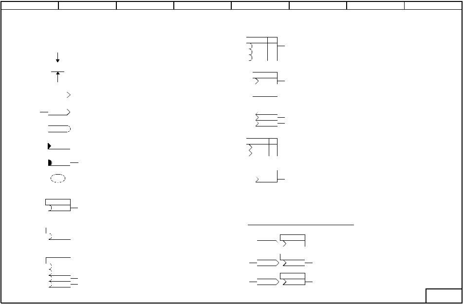
Key to symbols |
(see also Section 9.1) |
|
P462.F(10,00s) 0,01...300,00s
Ramp-up time
r045.02
Setting parameter
Factory setting in parentheses
".F"= parameter in a function parameter set 0.00...300.00s = setting range
Display parameter Parameter number = r045
.02 = index 2 of parameter
K0401 |
|
Connector |
|
(freely connectable 16-bit value) |
|
|
|
|
KK9498 |
|
Double-word connector |
|
(freely connectable 32-bit value) |
|
B0202 |
|
Binector |
|
(freely connectable binary signal) |
|
K0040 |
|
Connector assigned to a fixed quantity |
|
(i.e. not optional) |
|
|
|
|
B0161 |
|
Binector assigned to a fixed quantity |
|
(i.e. not optional) |
|
6 |
|
Identifier for a freely assignable |
|
function block |
|
|
|
(Number of function block) |
|
|
Selection of a binector |
P818 (1) |
|
Factory setting in parentheses |
B |
|
Setting range = all binector numbers |
|
|
Selected binector can be specified in symbol |
P697.B (1) |
|
Selection of a binector |
|
Factory setting in parentheses |
|
B |
|
".B" = Parameter in BICO data set |
|
|
Setting range = all binary numbers |
|
|
Selected binector can be specified in symbol |
P046 (0) |
.01 |
Selection of binectors via "indexed" parameter |
B |
Factory setting in parentheses |
|
B |
.02 |
Setting range = all binector numbers |
B |
.03 |
Selected binectors for each index can be specified |
B |
.04 |
|
|
|
5
U320 |
FS |
.01 |
B |
500 |
|
B |
510 |
.02 |
B |
1 |
.03 |
|
||
P510 (2) |
|
|
K |
|
|
P606 (9) |
.01 |
|
K |
|
|
|
.02 |
|
K |
|
|
|
.03 |
|
K |
|
|
|
.04 |
|
K |
|
|
|
|
|
P601 |
FS |
.01 |
K |
141 |
|
K |
0 |
.02 |
P510 (0) |
|
|
KK |
|
|
[G152.1] |
|
|
6 |
7 |
8 |
Selection of binectors via "indexed" parameter Factory settings differ for each index
Setting range = all binector numbers
Selected binectors for each index can be specified in symbol
Selection of a connector
Factory setting in parentheses
Setting range = all binector numbers
Selected connector can be specified in symbol
Selection of connectors via "indexed" parameter Factory setting in parentheses
Setting range = all connector numbers Selected connectors for each index can be specified in symbol
Selection of connectors via "indexed" parameter Factory settings differ for each index
Setting range = all connector numbers Selected connectors for each index can be specified in symbol
Selection of a double-word connector
Factory setting in parentheses
Setting range = all connector numbers
Selected connector can be specified in symbol
Reference to another sheet in function diagrams, destination symbol [Sheet.Column]
2007.05 symbols to Key
Selection of double-word connectors:
x |
|
U181 (0) |
|
y - LOW word = LOW word of x (KK9498) |
|
KK9498 |
KK9498 |
y |
|||
|
y - HIGH word = HIGH word of x (KK9498) |
||||
x |
|
U181 |
|
y - LOW word = 0 |
|
K0401 |
KK 401 |
y |
|||
|
y - HIGH word = x (K0401) |
||||
x |
|
P044 |
|
|
|
KK9498 |
K 9498 |
y y (Word) = HIGH word of x (KK9498) |
|||
|
|||||
- 000 -
diagrams Function
6-8 |
2 |
3 |
4 |
5 |
6 |
7 |
1 |
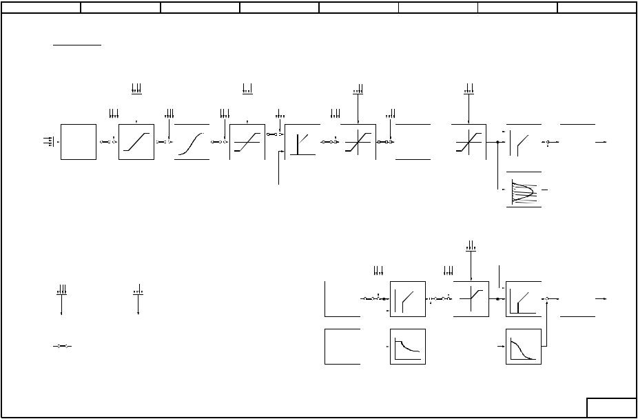
Overview
Setpoint limiting ramp-function generator
|
Additional |
Additional setpoint |
|
setpoint |
before r-f generator |
Main |
Setpoint |
|
setpoint |
processing |
|
Setpoint limiting |
Torque limits |
||
speed controller |
|
|
|
Additional |
Additional setpoint |
Additional |
Additional |
setpoint speed |
|||
controller limiting |
speed controller |
torque setpoint |
current setpoint |
Speed controller
Current setpoint  generation
[G110 - G130] Ramp-functiongenerator |
Ramp-function |
Setpoint |
[G151, G152] |
Torque limiting |
setpoint limiting |
generator |
limiting |
|
|
[G135] |
[G136] |
[G136] |
|
[G160] |
|
|
|
Actual value |
|
|
|
|
speed controller |
|
Armature current limits
Actual value armature current controller
|
Current |
|
controller |
Current limiting |
[G162] |
[G161] Precontrol
Field current limits
|
|
Legend : |
|
Additional setpoint |
Additional field |
Field current |
|
|
|
Additional setpoint |
EMF controller |
current setpoint |
actual value |
||
|
|
before r-f generator |
|
|
|
|
|
SIMOREG |
|
Additional setpoint |
from |
|
|
|
|
|
before r-f generator |
abcd |
EMF controller |
|
|
Current |
|
|
|
|
a ... Analog input |
|
|
||
|
|
equals |
b ... Serial interface |
EMF |
|
|
controller |
|
|
|
|
|
|||
|
|
|
c ... Basic converter function |
setpoint |
|
|
|
-DC |
|
|
d ... Supplementary board |
generation |
|
|
|
|
|
|
[G165] |
Current limiting |
[G166] |
||
MASTER |
SIEMENS |
|
|
||||
|
|
Precontrol |
[G165] |
|
Precontrol |
||
|
|
|
|
|
|||
|
|
|
|
|
|
||
|
|
= Parameterizable connection |
EMF |
|
|
|
|
|
|
actual value |
|
|
|
||
|
|
/disconnection points |
generation |
|
|
|
|
Instructions Operating |
0AD76-6RX1700 AG |
|
|
|
|
|
|
OverviewG100 Sheet |
diagramsFunction SheetsfunctionsBasic |
8 |
|
Armature |
G100 |
|
|
gating unit |
to |
|
|
[G163] |
G200 |
Field gating unit
[G166]
- G100 - |
.05 |
|
2007 |
||
|
DC SIMOREG |
AG SIEMENS |
MASTER- |
6RX1700 |
Operating |
0AD76- |
Instructions |
|
7-8
1 |
2 |
3 |
4 |
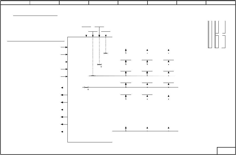
Hardware configuration
Select / deselect slots
U910.005 U910.003
U910.004 U910.002
Load class |
P067 |
Control word for |
P075 |
power section |
|
Reduction of converter |
P076 |
rated DC current |
|
Total thermal |
P077 |
reduction factor |
|
Reduction of converter |
P078 |
rated supply voltage |
|
Options according to rating plate |
r068 |
Serial number |
r069 |
MLFB (order number) |
r070 |
Converter rated |
|
|
Definition of SIMOREG DC Master power section |
||
supply voltage (armature) |
r071 |
|
|
||
Converter rated |
r072 |
|
DC current (armature) |
||
|
||
Converter rated |
r073 |
|
DC current (field) |
||
|
||
Converter rated |
r074 |
|
supply voltage (field) |
||
|
||
0
 1
1
0
1
0
 1
1
0
1
5 |
6 |
7 |
|
Board code |
|
Board compatibility |
Software identifiers |
|||||||||||
|
r063.002 |
|
|
|
r064.002 |
|
|
r065.002 |
|
||||||
|
|
|
|
|
|
|
|
|
|
|
|
|
|
|
Board in slot D |
|
r063.003 |
|
|
r064.003 |
|
r065.003 |
|||||||||
|
|
|
|
|
|
|
|
|
|
|
|
|
|
|
Board in slot E |
|
r063.004 |
|
|
r064.004 |
|
r065.004 |
|||||||||
|
|
|
|
|
|
|
|
|
|
|
|
|
|
|
Board in slot F |
|
r063.005 |
|
|
r064.005 |
|
r065.005 |
|||||||||
|
|
|
|
|
|
|
|
|
|
|
|
|
|
|
Board in slot G |
|
r063.001 |
|
|
r064.001 |
|
r065.001 |
|||||||||
|
|
|
|
|
|
|
|
|
|
|
|
|
|
|
Board in location 1 |
Software version |
|
|
Creation date |
|
|
|
|
||||||||
|
|
of software |
|
|
|
|
|
||||||||
|
|
|
|
|
|
|
|
|
|
|
|
|
|
|
|
.001 |
CUD |
|
.001 |
Year |
|
|
|
|
|||||||
.002 |
Slot D |
.002 |
Month |
|
Checksum |
||||||||||
.003 |
Slot E |
.003 |
Day |
|
|||||||||||
|
|
|
|
||||||||||||
.004 |
Slot F |
.004 |
Hour |
.001 Converter firmware |
|||||||||||
.005 |
Slot G |
.005 |
Minute |
.002 Boot sector |
|||||||||||
|
r060 |
|
|
r061 |
|
r062 |
|||||||||
Software
8
Arrangement of board locations 1 to 3 and slots D to G in electronics box
1 |
3 |
2 |
|
|
F |
|
D |
|
|
||
CUDx |
|
|
|
|
G |
|
E |
|
|
|
|
- G101 -
G101 Sheet |
2007.05 |
configuration Hardware |
|
diagrams Function
8-8
MASTER-DC SIMOREG |
SIEMENS |
Instructions Operating |
0AD76-6RX1700 AG |
1 2 3 4 5 6 7 8
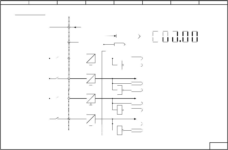
Binary inputs (1)
X171 |
CUD1 |
|
|
|
|
|
|
|
|
|
|
34 |
P24_S |
|
Display of terminal states on 7-segment display |
||||||||
|
|
||||||||||
|
|
|
|
|
|
E- |
214 |
213 |
212 |
211 |
|
|
|
r010 |
|
|
|
Stop |
|||||
|
|
|
|
|
|
|
|
|
|
|
|
35 |
|
|
43 |
42 |
41 |
40 |
|
39 |
38 |
37 |
36 |
M |
K0020 |
|
|
|
|
|
|
|
|
|
|
|
|
|
|
|
|
|
|
|
|
||
|
|
|
|
|
|
|
|
|
|
||
|
|
|
|
|
|
|
|
|
|
|
|
36 |
24V |
|
B0010 |
|
|
|
|
|
|
|
|
|
5V |
|
|
|
|
|
|
|
|
|
|
|
|
|
|
|
|
|
|
|
|
|
|
|
M |
1 |
B0011 |
|
|
|
|
|
|
|
|
37 |
24V |
|
Switch-on/Shutdown (to Sheet "Crawling setpoint / Terminal 37") |
|
|||||||
|
5V |
|
|
||||||||
|
|
[G130.1] |
|
|
|
|
|
|
|
|
|
|
|
|
|
|
|
|
|
|
|
|
|
|
|
|
B0012 |
|
|
|
|
|
|
|
|
|
M |
1 |
|
|
|
|
|
|
|
|
|
|
|
B0013 |
|
|
|
|
|
|
|
|
|
38 |
24V |
|
Enable operation (to sheet "Control word 1") |
|
|
|
|
|
|
||
|
5V |
|
|
|
|
|
|
|
|||
|
|
[G180.2] |
|
|
|
|
|
|
|
|
|
|
|
|
|
|
|
|
|
|
|
|
|
|
|
|
B0014 |
|
|
|
|
|
|
|
|
|
M |
1 |
|
|
|
|
|
|
|
|
|
|
|
B0015 |
|
|
|
|
|
|
|
|
|
39 |
24V |
|
IRES (to sheet "Pulse encoder evaluation") |
|
|
|
|
|
|
||
|
5V |
|
|
|
|
|
|
|
|||
|
|
[G145.2] |
|
|
|
|
|
|
|
|
|
|
|
|
|
|
|
|
|
|
|
|
|
|
|
|
B0016 |
|
|
|
|
|
|
|
|
|
M |
1 |
|
|
|
|
|
|
|
|
|
|
|
B0017 |
|
|
|
|
|
|
|
|
|
- G110 -
Binary G110 Sheet |
diagrams Function |
39 to 36 terminals inputs |
|
2007.05
05.2007 |
Function diagrams |
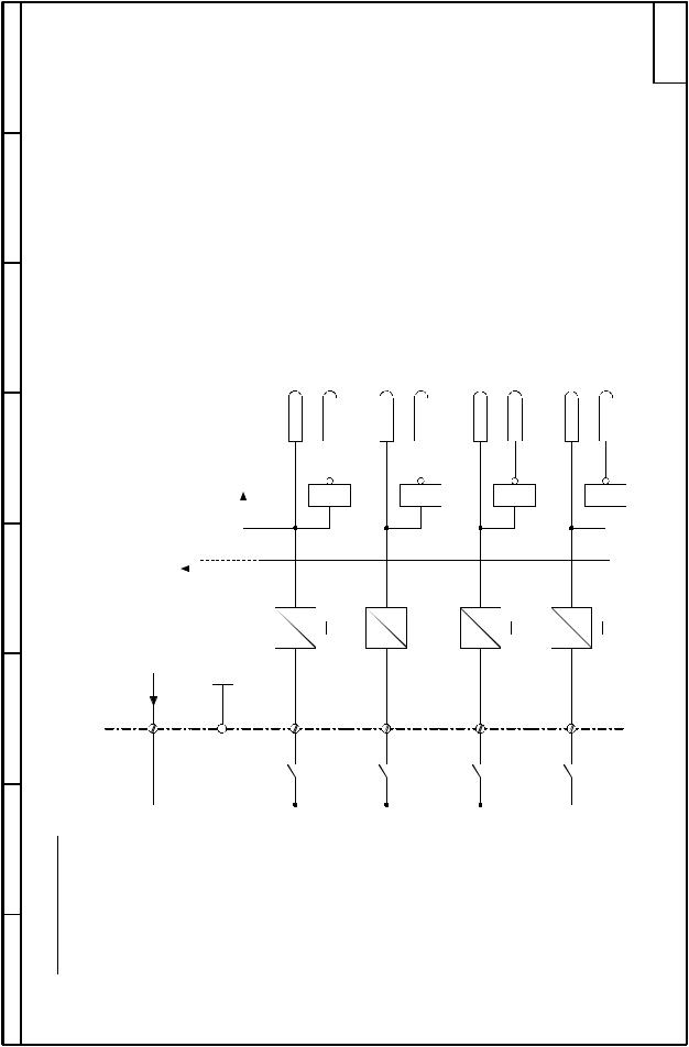
Sheet G111 Binary inputs terminals 40 to 43 |
|
8 |
- G111 - |
7
6
5
4
For display of terminal states on 7-segment display, see block diagram "Binary inputs (1)" |
[G145.2] Enable counter for zero markers (to sheet "Pulse encoder evaluation") |
B0018 |
1 B0019 |
B0020 |
1 B0021 |
B0022 |
1 B0023 |
B0024 |
1 B0025 |
3 |
CUD2 |
S |
24V |
5V |
M |
24V |
5V |
M |
24V |
5V |
M |
24V |
5V |
M |
P24_ |
M |
|
|
|
|
|
|
|
|
|
|
|
|
|
|
|
|
|
|
|
|
|
|
|
X163 |
44 |
45 |
40 |
41 |
42 |
43 |
2 |
(2) |
1 |
Binary inputs |
|
SIEMENS AG 6RX1700-0AD76 |
8-9 |
SIMOREG DC-MASTER Operating Instructions |
|