

Газовые турбины GE
.pdfMS5002C-D Gas Turbines
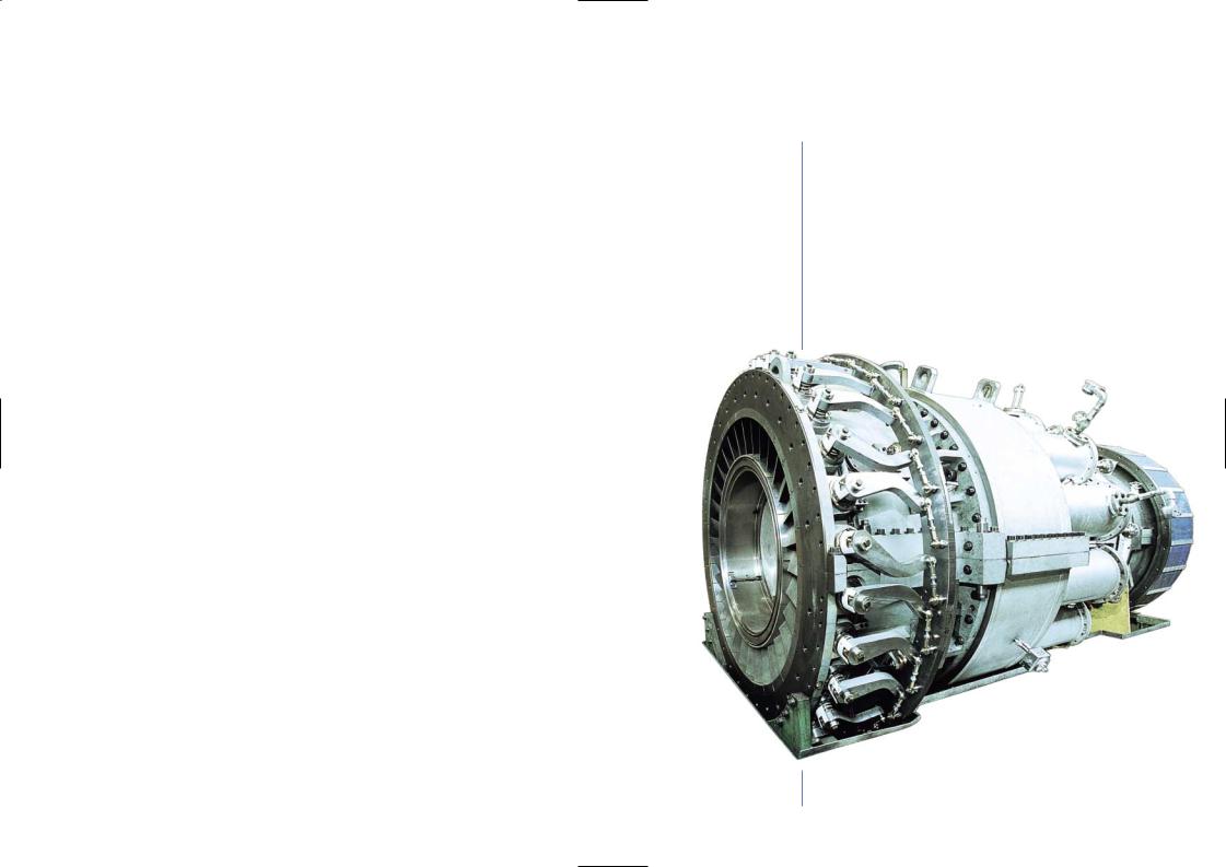
The MS5002 is a gas turbine specifically designed for mechanical drive applications such as gas boosting, gas injection/re-injection, oil & gas pipelines, LNG plants and gas storage. It has a broad operating speed range to meet the operating requirements of the most common driven equipment (centrifugal compressors and pumps) as well as the ability to burn a large variety of gaseous and liquid fuels. The MS5002 gas turbine was introduced in the market in the 1970s and has been updated and up-rated over the years to meet the industry demand for increased output. Presently two versions are available:
-MS5002C
-MS5002D
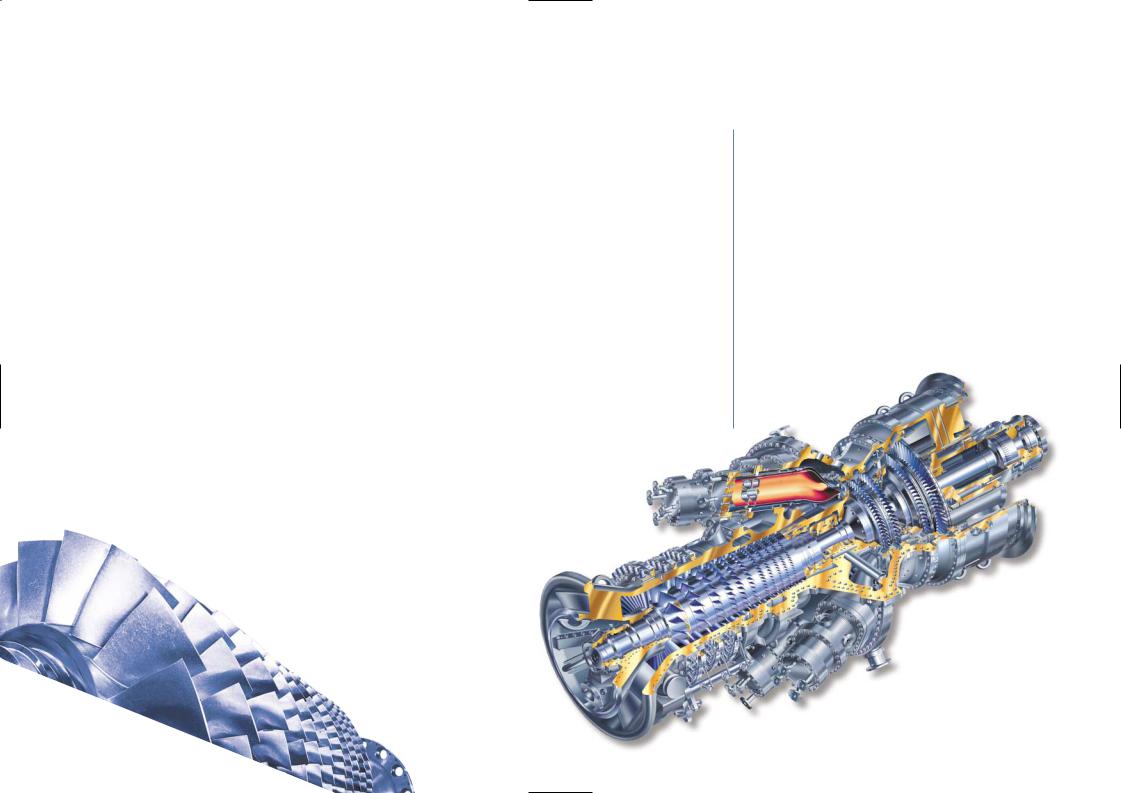
The MS5002 two-shaft, heavy-duty gas turbine is designed for high operating efficiency over a wide range of speed and load. The simple design and extreme robustness of the MS5002 allow complete maintenance to be performed on site without the need for specialized tooling or service shop assistance. The main features of its design are:
-High pressure shaft consisting of a 16-stage (17 for MS5002D), axial-flow compressor and a single-stage, high energy turbine. The first stage nozzles are air cooled and the second stage nozzles are of the variable angle type.
-Low pressure shaft is a single stage, high energy turbine.
-Twelve combustion chambers are contained within a single wrapper. A wide range of gaseous and liquid fuels can be burned. A DLN Combustion System is also available.
-A centralized lube oil system supplies clean, cooled, pressurized oil to lubricate the gas turbine
and the driven equipment including the oil required for any compressor seals.
As a consequence of the extremely favorable operating, maintenance and economic characteristics of the MS5002 nearly 500 units (more than 300 manufactured by GE’s Oil & Gas business) have been installed world-wide in all types of environments (arctic, desert, off-shore etc.) always demonstrating ease of operation and very high reliability and availability.
MS5002 Gas Turbine
11 GE Gas Turbines
MS5002E Gas Turbines
The MS5002E, the latest addition to the GE family of gas turbines, is a 32MW class machine designed for high efficiency, low environmental impact and high reliability. The MS5002E will be available in both single and dual-shaft versions to cover power generation and mechanical drive applications.
This latest model was developed in response to customer demand for a machine in the 32 MW range with low fuel consumption, reduced emissions and high availability and reliability. In order to guarantee high reliability and availability the MS5002E has a conservative firing temperature with respect to the state-of-the-art. High efficiency was achieved through the use of advanced design tools to optimize airfoils, clearances, leakages and the distribution of cooling flows.
The MS5002E offers NOx emission levels down to 25 ppm through the use of a dry-low emission combustion system derived from GE’s DLN2 combustion technology.
The design of the MS5002E was thoroughly validated through an extensive test program that included a full scale test of the axial compressor, full scale rotordynamic
testing of the gas turbine system.
The MS5002E single and dual-shaft 32MW class machine represents a achievement to provide customers with a high efficiency, low emissions reliability matched for Oil & Gas Industry applications.
MS5002E Gas Turbine
EXPECTED PERFORMANCE |
|
Output Shaft |
32 MW |
|
|
SC Efficiency |
36% |
|
|
Pressure Ratio |
17:1 |
|
|
LPT Shaft Speed |
5714 rpm |
|
|
Exhaust Temperature |
511 °C |
|
|
NOx Emission |
25 ppm |
|
|

MS6001B/MS7001EA/MS9001E
Available for Oil & Gas Applications
APPLICATIONS
The 7EA is fuel-flexible, and can operate on natural gas, liquefied natural gas (LNG), distillate and treated residual oil in a variety of applications including:
-mechanical drive for large compressor trains
-simple cycle and combined cycle
-base load and peaking power generation
-industrial and cogeneration
FEATURES
-17-stage compressor with stacked disk design
-reverse flow combustion system with an individual nozzle single combustion chamber
-3-stage turbine with air-cooled, first and second-stage nozzles and buckets
-three-bearing rotor supports
MS6001B
The MS6001 is a single-shaft, heavy-duty gas turbine. The high efficiency axial compressor has 17 stages. The combustor has ten combustion chambers with individual fuel nozzles. The machine has a three-stage impulse turbine with air-cooled buckets and stationary nozzles on the first two stages to achieve higher firing temperatures and consequently higher efficiency without compromising hot section component life.
MS6001B
Gas Turbine
MS7001EA
The MS7001EA is a highly reliable, mid-sized packaged power plant developed specifically for 60 Hz applications. With design emphasis placed on energy efficiency, availability, performance and maintainability, the 7EA is a proven technology machine with more than 775 units of its class installed or on order worldwide as of December 1999. The simple, medium-sized design of the 7EA lends itself to flexibility in plant layout and easy, low cost addition of power augmentation when phased capacity expansion is needed. A predecessor of the 7FA, the 7EA is ideal for plants that require high efficiency along with shaft speed for direct coupling to
MS7001EA
Gas Turbine
MS9001E
The MS9001 is a single-shaft, heavy-duty gas turbine developed for generator drive service in the 50 Hz market. Its efficiency is approx 33% in simple cycle mode and over 50% when operated as a combined cycle. The MS9001 is designed to burn a variety of liquid and gaseous fuels.
MS9001E
Gas Turbine
13 GE Gas Turbines
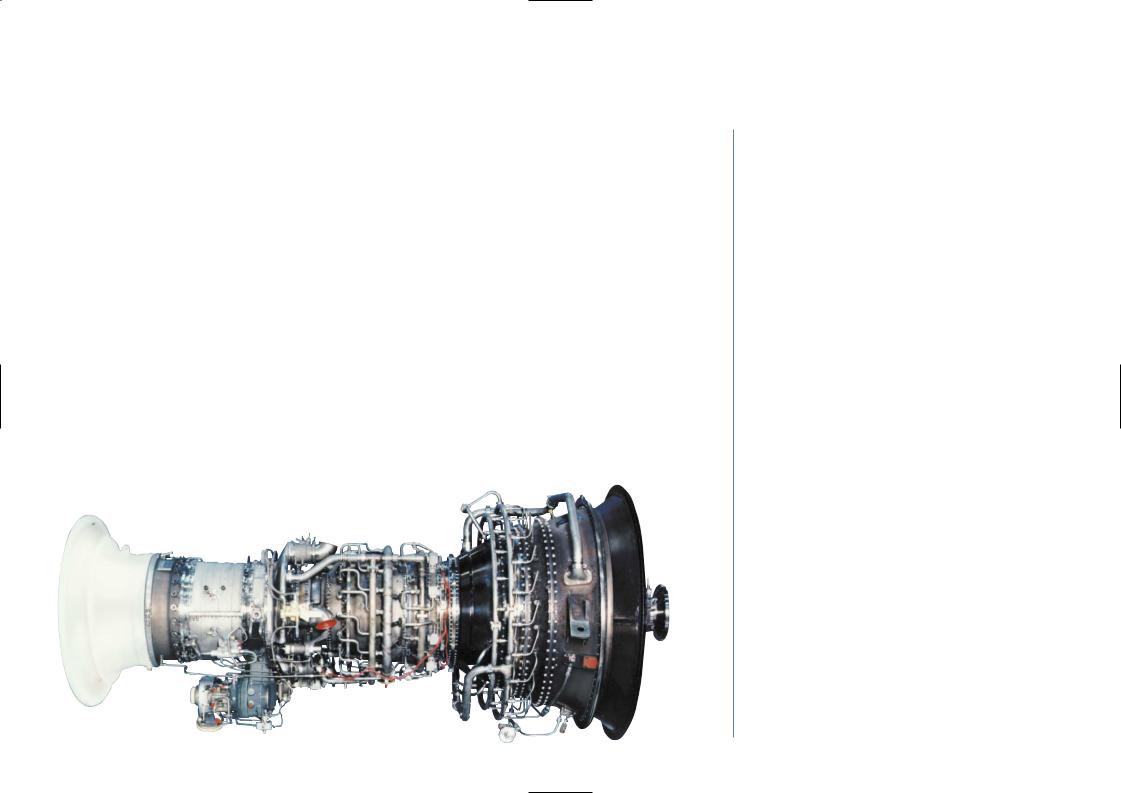
PGT16 Aeroderivative Gas Turbines
The PGT16 gas turbine consists of the twin spool GE Aeroderivative LM1600 Gas Generator coupled with a rugged, industrial power turbine designed by GE’s Oil & Gas business. The LM1600 Gas Generator is derived from the F404 turbofan aircraft engine.
The power turbine of the PGT16 gas turbine is identical to that of the PGT10 heavy duty, high efficiency gas turbine which has been in operation for more than half a million hours.
The power turbine shaft speed (7900 RPM) is optimized for direct coupling to pipeline, injection and process centrifugal compressors with a speed range that matches most operating requirements encountered in oil & gas applications. For generator drive applications the PGT16 synchronously coupled to a generator with a speed reduction gear is a highly flexible turbogenerator which can be operated as a simple cycle or in combined or cogeneration cycle applications with an electrical efficiency close to 50%.
PGT16 Gas Turbine
GENERAL SPECIFICATIONS
Compressor
-Twin spool axial compressor (3 stage LP compressor, 7 stage HP compressor)
-Pressure ratio 20.1:1
Combustion
- Annular combustion chamber (18 fuel nozzles)
Turbine
-Twin Spool Gas Generator turbine (1 stage HP turbine, 1 stage LP turbine)
-Two stage Power turbine with variable angle first stage nozzles
Package
-Completely mounted on a single base plate
-The enclosure is integral with the base plate providing maximum accessibility for maintenance of the gas turbine and auxiliaries
Emission Control
-Steam or water injection systems for NOx abatement
-Dry Low Emission (DLE) combustion system
14 GE Gas Turbines

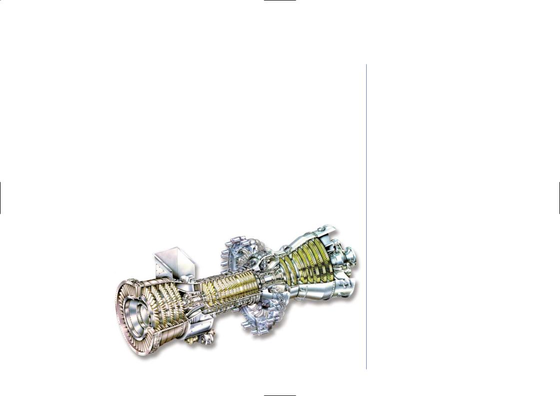
PGT25 Aeroderivative Gas Turbines
The PGT25 gas turbine consists of an LM2500 GE aeroderivative gas generator coupled with a rugged, industrial power turbine designed by GE’s Oil & Gas business.
GAS GENERATOR
The LM2500 gas generator has already accumulated several million fired hours not only as an aircraft engine (TF39 and CF6-6 engines), but also in the industrial field in many mechanical drive applications (marine, onshore and offshore gas transmission) and for generator drive service. The LM2500 gas generator incorporates a 16-stage axial-flow compressor capable of reaching an 18:1 pressure ratio. Inlet guide vanes and adjustable stator vanes on the first six compressor stages provide for efficient operation over the entire operating range.
POWER TURBINE
The PGT25 power turbine components were designed taking into account many years of experience gained in the field of heavy duty gas turbines and axial/centrifugal compressors. The aerodynamic blading was designed with the main objective of obtaining very high efficiency at both design and reduced speeds.
The 6500 RPM design speed means the turbine can have two stages with a moderate aerodynamic load and a high expansion efficiency. The two expansion stages are of the high energy, three-dimensional design type.
The investment casting superalloy selected for the blading assembly has a cobalt base for the nozzles and a nickel base for the rotor blading (i.e. the same materials used on heavy-duty gas turbines). A large creep and fatigue (LCF-HCF) safety margin on blade life is ensured by a moderate gas temperature at the power turbine inlet. The two-stage rotor is overhung and the shaft is supported by two tilting pad bearings contained in a cylindrical cartridge. The system can be easily dismantled with a simple translation of the gas generator within the package space thus reducing the time required for a major overhaul of the power turbine to a few days. Engineering simplicity and advanced materials yield long time between overhauls and reduced maintenance costs.
The turbine is assembled on a light but rigid base plate with extensive use of prefabricated standard components preassembled and tested in the shop to minimize on-site assembly time.
GENERAL SPECIFICATIONS
Compressor
-Sixteen stage axial compressor
-Pressure ratio 17.7:1
Combustion
- Annular combustion chamber (30 fuel nozzles)
Turbine
-Two stage Gas Generator turbine
-Two stage Power turbine (6500 RPM).
Package
-Completely mounted on a single base plate
-The enclosure is integral with the base plate providing maximum accessibility for maintenance of the gas turbine and auxiliaries
Emission Control
-Steam or water injection systems for NOx abatement
-Dry Low Emission (DLE) combustion system
PGT25 Gas Turbine
15 GE Gas Turbines
PGT25+ Aeroderivative Gas Turbines
The PGT25+ gas turbine was developed for 30 MW ISO shaft power service with the highest thermal efficiency level (approx. 40%). The PGT25+ gas turbine consists of the GE Aeroderivative LM2500+ Gas Generator (updated version of the LM2500 gas generator with the addition of a zero stage to the axial compressor) coupled with a 6100 RPM, 2 stage Power Turbine (High Speed Power Turbine - HSPT). Built on the LM2500 heritage and demonstrated 99.6% reliability, the LM2500+ incorporates technology improvements and a large percentage of parts in common with the LM2500 to deliver the same outstanding level of reliability. Designed for ease of maintenance, the LM2500+ also provides a high level of availability. High efficiency and reliability are among the large number of benefits contributing to PGT25+ customer value.
Specialized aeroderivative annular combustion chamber fuel nozzles makes the PGT25+ ideal for a wide range of mechanical drive (gas pipeline, etc.), power generation, industrial cogeneration, and offshore platform uses in any environment.
Engineering simplicity and advanced materials yields long time between overhauls and reduce maintenance costs.
PGT25+ Gas Turbine
GENERAL SPECIFICATIONS
Compressor
-Seventeen stage axial compressor
-Pressure ratio 21 15:1
Combustion
- Annular combustion chamber (30 fuel nozzles)
Turbine
-Two stage Gas Generator turbine
-Two stage Power turbine (6100 RPM).
Package
-Gas Generator, Power Turbine and auxiliary systems mounted on a single base plate
-The enclosure is integral with the base plate providing maximum accessibility for maintenance of the gas turbine and auxiliaries
Emission Control
-Steam or water injection systems for NOx abatement
-Dry Low Emission (DLE) combustion system
16 GE Gas Turbines
LM6000 Aeroderivative Gas Turbines
The LM6000 is a simple-cycle, two-shaft, high performance gas turbine derived from the
GE CF6-80C2 high bypass turbofan aircraft engine, the industry standard for high-thrust engines. Delivering more than 44.8 MW at over 42.7% thermal efficiency, the powerful LM6000 is the most fuel-efficient, simple-cycle gas turbine in the world. Direct drive provides 60,000 shaft horsepower from either end of the low pressure rotor for a wide range of electric power generation and mechanical drive applications in any environment.
High thermal efficiency, low cost, and installation flexibility make the LM6000 the ideal choice as a prime driver for utility peaking, mid-range, and base load operations, as well as for industrial cogeneration.
The LM6000’s design allows full speed range capability from 50-105% of the rated speed of 3600 RPM. Continuing the tradition of the established record of GE’s LM2500, the LM6000 is ideal as a source of drive-power for pipeline compression, offshore platform and gas re-injection, as well as for LNG compressors. The LM6000 was GE’s first aeroderivative gas turbine to employ the new Dry Low Emissions (DLE) premixed combustion system. DLE dual fuel, water or steam injection can also be used to achieve low NOx emissions.
GENERAL SPECIFICATIONS
Compressor
-Two axial compressor (LPC, HPC)
-LPC five stage
-HPC fourteen stage
-Pressure ratio 28.5:1
Combustion
- Annular combustion chamber (30 fuel nozzles)
Turbine
-Two stage HPT
-Six stage LPT (3600 RPM)
Package
-Gas Generator, Power Turbine and auxiliary systems mounted on a single base plate
-The enclosure is integral with the base plate providing maximum accessibility for maintenance of the gas turbine and auxiliaries
Emission Control
-Steam or water injection systems for NOx abatement
-Dry Low Emission (DLE) combustion system
LM6000 Gas Turbine
17 GE Gas Turbines
Main Components
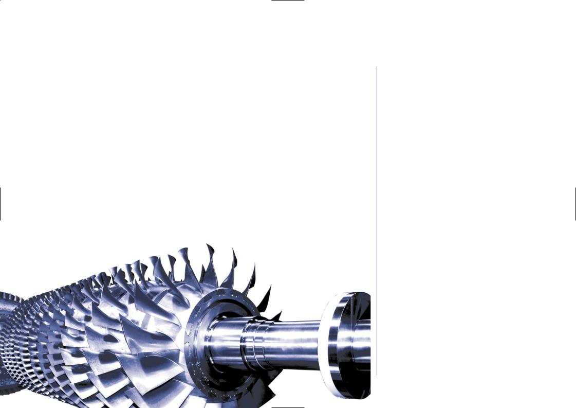
Axial Compressor
The compressor rotor is made of separately forged wheels (all models except the GE5 and part of the GE10 which have a solid forged rotor). Each individual wheel undergoes inspection and is X- rayed for material flaws. In addition, each wheel is balanced individually and the rotor is balanced on three planes. Rabbet fits are used to ensure concentricity and multiple through-bolts secure the wheels to form a correctly pre-stressed assembly. The blades are held in the compressor rotor and stator rings by dovetail platforms. The stainless steel blades provide excellent corrosion resistance and good internal damping characteristics. The large chord, broadblade compressor blades have low stresses and the unique ability to withstand damage by small foreign objects as well as to maintain high performance in spite of normal wear and contamination. The stator casing is horizontally split for ease of assembly, maintenance and inspection. Iron castings give dimensional and thermal stability to maintain good radial tip clearances for maximum power and efficiency. Several compressor designs are available covering pressure ratios in the 8-17 range and air flows from 20 to 400 Kg/sec with 11-17 stage configurations. The GE5, GE10 and MS5002E compressors have variable geometry, implemented by means of adjustable vanes (inlet guide vanes and first stage stator vanes), in order to provide flow control within the operating range.
18 GE Gas Turbines

First Stage Nozzle
The complete first stage nozzle assembly consists of airfoil-shaped vanes which are contained between an inner and an outer sidewall. The design of the nozzle assembly and the arrangement for its support within the turbine shell accommodate the effects of thermal expansion
the hot gases and keep the assembly properly aligned in the gas path. Seals in shell prevent leakage of combustion gases around the nozzle from the inlet to the exhaust. Compressor discharge air is fed to these sealing rings through orifices in the shell. A key feature of the first-stage nozzle is the air-cooled partition which increases nozzle life substantially. Cooled air from the compressor discharge is directed through the body of the individual nozzle partitions and out holes near the trailing edge. This not only cools the metal, but blankets the trailing edge with a film of air. Additionally, relatively thick nozzle partition trailing edges provide increased strength and oxidation resistance, again providing longer nozzle life.
Buckets and Wheels
The long shank bucket design lowers the turbine wheel rim a substantial distance below the hot gas path. The high thermal resistance of the shank results in a considerable temperature drop between the hot bucket vane and the wheel dovetail, thus reducing temperature levels and gradients in the turbine wheel and the dovetail area where rotating stresses are high. Further wheel protection is provided by radial seals on the first-stage bucket shanks that restrict hot gas leaks into the wheel cavities. Compressor bleed air is used to cool the wheels and maintain relatively low temperature levels.
19 GE Gas Turbines
Gas Turbine Operability
Large Operability Window
A variety of innovative design solutions are offered to maximize the operability window of the Oil & Gas gas turbine fleet. In addition to variable stator vanes and blow-off valves, the design solutions include:
-variable turbine nozzle guide vanes
-a variable bypass combustion chamber
-a high turn-down capability combustion chamber
-CPC optimizing control logic
The various combinations of design solutions are specifically adapted to the demands of the marketplace for each gas turbine model.
For example: The GE10-2 DLN (Dry Low NOx) model utilizes a variable bypass combustion chamber to maintain the optimum flame temperature for low emissions all the way down to 50% load, and the variable nozzle guide vanes of the free power turbine to ensure that the gas generator shaft speed is always at the design value, thereby ensuring maximum output.
The MS5002D instead uses variable nozzle guide vanes to maintain maximum output on the standard model, and to maintain the optimum flame temperature for low emissions down to 50% load on the DLN model. They are also used in regenerative cycle applications to maximize the efficiency of the regenerator and hence to maximize fuel economy.
The brand new MS5002E makes use of the DLN2 combustion design used in GE’s F-Class machines to ensure low emissions over a range of flame temperatures, thereby delaying the opening of the blow-off valves at part load while maintaining the highest possible efficiency at base-load.
Note that the flexibility given by each of these solutions delivers a further performance advantage on cold days with respect to other engines that are forced to open blow-off valves (to meet environmental emissions laws) even at base-load.
MS5002D Gas Turbine
20 GE Gas Turbines