

ChaoticCDMACommunicationsystems
.pdfInternational Journal of Bifurcation and Chaos, Vol. 7, No. 12 (1997) 2789{2805c World Scienti c Publishing Company
2805. Downloaded from www.worldscientific.com |
02/14/13. For personal use only. |
Chaos 1997.07:2789- |
by 128.73.53.214 on |
Int. J. Bifurcation |
|
CHAOTIC DIGITAL CODE-DIVISION MULTIPLE ACCESS
(CDMA) COMMUNICATION SYSTEMS
TAO YANG and LEON O. CHUA
Electronics Research Laboratory and
Department of Electrical Engineering and Computer Sciences,
University of California at Berkeley,
Berkeley, CA 94720, USA
Received June 26, 1997; Revised August 18, 1997
In this paper, the structure, principle and framework of chaotic digital code-division multiple access ((CD)2 MA) communication systems are presented. Unlike the existing CDMA systems, (CD)2MA systems use continuous pseudo-random time series to spread the spectrum of message signal and the spread signal is then directly sent through a channel to the receiver. In this sense, the carrier used in (CD)2MA is a continuous pseudo-random signal instead of a single tone as used in CDMA. We give the statistical properties of the noise-like carriers. In a (CD)2MA system, every mobile station has the same structure and parameters, only different initial conditions are assigned to di erent mobile stations. Instead of synchronizing two binary pseudo-random sequences as in CDMA systems, we use an impulsive control scheme to synchronize two chaotic systems in (CD)2MA. The simulation results show that the channel capacity of (CD)2MA is twice as large than that of CDMA.
1. Introduction
In the 1980s, many analog cellular communication networks were implemented over the world. These networks are already reaching their capacity limits in several service areas. This wireless communication technology has evolved from simplerst-generation analog systems for business applications to second-generation digital systems with rich features and services for residential and business environments. There are several reasons for the transition from wireless analog to digital technology: Increasing tra c, which requires greater cell capacity, speech privacy, new services and greater radio link robustness.
During the late 1980s and early 1990s, the rapid growth in mobile communications put a high demand on system capacity and the availability of the technology for low-cost implementation of cellular and personal communication services (PCS) [Gang et al., 1997]. CDMA has a larger system
capacity than the existing analog systems. The increased system capacity is due to the improved coding gain/modulation density, voice activity, threesector sectorization, and the reuse of the same spectrum in every cell. CDMA is a cost-e ective technology that requires fewer, less-expensive cells and no costly frequency reuse pattern. The average power transmitted by the CDMA mobile stations averages about 6{7 mW, which is less than one tenth of the average power typically required by FM and TDMA phones. Transmitting less power means longer battery life. CDMA can improve the quality-of-service by providing both robust operation in fading environments and transparent (soft) hand-o . CDMA takes advantage of multi-path fading to enhance communications and voice quality. In narrow-band systems, fading causes a substantial degradation of signal quality.
Since some new services, such as wide-band data and video, are much more spectrum-intensive
2789
2805. Downloaded from www.worldscientific.com |
02/14/13. For personal use only. |
Chaos 1997.07:2789- |
by 128.73.53.214 on |
Int. J. Bifurcation |
|
2790 T. Yang & L. O. Chua
than voice service, even the channel capacity improvement provided by CDMA will be depleted in the near future. This motivates some advanced wireless communication schemes, which can provide a bigger capacity. In this paper, we present a chaotic digital CDMA scheme. Before we design a chaotic digital CDMA system, we should solve the following problems.
1.1. Spreading carriers
In CDMA systems, pseudo-random signals are used to
(1)spread the bandwidth of the modulated signal to the larger transmission bandwidth and
(2)distinguish among the di erent user signals which are using the same transmission bandwidth in the multiple-access scheme.
Ideally, these pseudo-random signals should be samples of a sequence of independent random variables, uniformly distributed on an available alphabet or range. In this case, the CDMA system is equivalent to a one-time pad used in cryptographic system requiring the highest level of security. Since the key signal in a one-time pad should be as long as the message signal, it is not feasible to use it in CDMA [Simon et al., 1994].
We must gure out a way to store/generate good pseudo-random signals in both the transmitter and the receiver, despite the nite storage capacity/generating capacity of physical processing systems. It would be very expensive and energy ef-cient to generate such a sequence by using some chaotic circuits, e.g. Chua's circuits. In fact, some methods to generate good pseudo-random signals for cryptographic purposes by using Chua's circuits [Yang et al., 1997] have been already developed.
1.2. Orthogonal functions
Orthogonal functions are used to improve the bandwidth e ciency of a spread spectrum system. In CDMA, each mobile station uses one set of orthogonal functions representing the set of symbols used for transmission. Usually, the Walsh and Hadamard sequences are used to generate this kind of orthogonal functions for CDMA. In (CD)2MA, it is di cult to nd a theory to guarantee that the spectrumspreading carriers are orthogonal. However, from simulations we nd that there exist many methods
to generate signals, which have very small cross correlations, by using chaotic signals. We can therefore choose good spectrum-spreading carriers from several promising candidates.
In CDMA, there exist two di erent methods of modulating the orthogonal functions into the information stream of the CDMA signal. The orthogonal set of functions can be used as the spreading code or can be used to form modulation symbols that are orthogonal. In (CD)2MA, however, the \orthogonal function" itself serves as the carrier.
1.3. Synchronization considerations
In a CDMA system, the heart of the receiver is its synchronization circuitry, and the heartbeats are the clock pulses which control almost every step in forming the desired output. There exist three levels of synchronization in a CDMA system:
(1) correlation interval synchronization, (2) spreadspectrum generator synchronization and (3) carrier synchronization.
To correlate the Walsh codes at the receiver, the receiver is required to be synchronized with the transmitter. In the forward direction, the base station can transmit a pilot signal to enable the receiver to recover synchronization. Just as the designers of the IS-665 wide-band CDMA system believed, with a wider bandwidth the base station can also recover the pilot signal sent by mobile stations. In (CD)2MA, we also use this symmetric system between the base station and the mobile station.
In the (CD)2MA system, we need to synchronize two chaotic systems. If we use the continuous synchronization scheme, we need a channel to transmit the chaotic signal. Even though we can embed a message signal into a chaotic carrier [Halle et al., 1993], we cannot achieve a chaotic CDMA system. A promising method to improve this is the framework of impulsive synchronization [Yang & Chua, 1997a, 1997b]. In this paper, we will show that the (CD)2MA system does not need the correlation interval synchronization and carrier synchronization. This makes the receiver in (CD)2MA simple and low-power.
The (CD)2MA system can increase the capacity of a radio channel. For mobile subscribers, this increased capacity translates to better service at a lower price. On the other hand, (CD)2MA is also a promising technology for low-cost implementation
2805. Downloaded from www.worldscientific.com |
02/14/13. For personal use only. |
Chaos 1997.07:2789- |
by 128.73.53.214 on |
Int. J. Bifurcation |
|
of cellular and PCS. The organization of this paper is as follows. In Sec. 2, we present the structure of (CD)2MA system. In Sec. 3, we study the randomness of spreading carriers. In Sec. 4, we give the concept of impulsive synchronization. In Sec. 5, we show that a (CD)2MA system has a larger channel capacity than CDMA. Section 6 contains the conclusion.
2.Structures of CDMA and (CD )2MA Systems
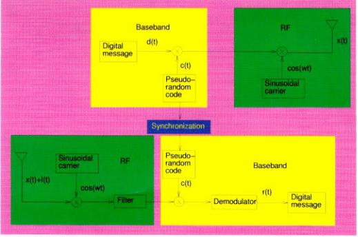
Information can be modulated into the spreadspectrum signal by several methods. The most common method is to add the information into the spectrum-spreading code before it is used for modulating the carrier frequency. The corresponding CDMA system is shown in Fig. 1. In Fig. 1, d(t) and c(t) are respectively called \message signal" and \spreading signal". The signal cos(!t) is called the carrier, and x(t) is the encoded signal. At the receiver end, I(t) is the interference signal which consists of channel noise, interference and/or jamming, and r(t) is the recovered signal. d(t) is a low frequency digital message signal with a data rate 9:6 kbps for IS-95 CDMA system. c(t) is a high frequency spreading signal with a chip rate
Chaotic Digital CDMA Communication Systems 2791
1:2288 Mcps for IS-95 CDMA system. We can see that the chip rate is much higher than the data rate. This is the method by which the bandwidth of the message signal is spread.
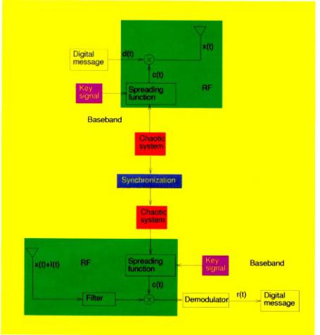
On the other hand, the message signal can also be used to modulate the carrier directly, given the carrier also functions as spectrum-spreading signal. In (CD)2MA system, we use this kind of modulation scheme. The corresponding (CD)2MA system is shown in Fig. 2.
Comparing the (CD)2MA system in Fig. 2 with the CDMA system in Fig. 1, we can see that both schemes use the synchronization of two identical spreading carrier generators. Instead of modulating a single tone (an RF sinusoidal signal) as in the CDMA system, a (CD)2MA system transmits a pseudo-random RF spreading carrier directly. We give the details of every block in Fig. 2. To enhance the security of the (CD)2MA system, we can also use two key signals to scramble the spreading carrier. The key signal can be assigned to each transmitter and receiver pair by the base station (cell). Since each mobile station can function either as a transmitter or as a receiver, we suppose that the key signals are set by both the receiver and the transmitter and can be refreshed during conversations. The key signals may only be used in cases where a very high security should be taken into
Fig. 1. The Block diagram of the CDMA system.
2805. Downloaded from www.worldscientific.com |
02/14/13. For personal use only. |
Chaos 1997.07:2789- |
by 128.73.53.214 on |
Int. J. Bifurcation |
|
2792 T. Yang & L. O. Chua
Fig. 2. The Block diagram of the (CD)2MA system.
account (e.g. military applications). In commercial applications, the spreading signal is all along secure enough.
In the (CD)2MA paradigm, every mobile station has the same chaotic circuit, e.g. Chua's circuit. Whenever two users are connected by the base station, they are assigned the same set of initial conditions to their chaotic circuits. Then, the impulsive synchronization scheme is used to maintain the synchronization between the two chaotic circuits.
Since the chaotic circuit works in a low frequency range, we need a spreading function to spread it into bandwidths in the MHz range. In principle, there are many nonlinear functions which can be used as spreading functions. In this paper, the spreading function is chosen according to that used in [Yang et al., 1997]. That is, we use an n-shift scheme to spread the spectrum of the chaotic signal. The chaotic systems in both transmitter and receiver are identical and the synchronization between
them is achieved by a new chaotic synchronization scheme called impulsive synchronization. The demodulator consists of some low-pass ltering and thresholding blocks.
3.Statistical Properties of Chaotic Spreading Carriers
We now study the properties of the spreading signal, which should have a narrow autocorrelation function for achieving a big channel capacity and small cross-relations. One of the ideal candidates for this kind of signal is white noise which has an autocorrelation function of a Dirac Delta function at the origin. Although from a deterministic model we cannot generate a true white noise signal, we still have the chance to generate its approximation which we call a pseudo-random signal. Since the cryptographic community has spent half a century trying to nd a good binary pseudo-random
signal for the purpose of a high level of security of cryptographic algorithms, we borrow some methods used by them.
We rst use a chaotic system to generate a good seed signal (low frequency in the range of KHz) and then use some spreading function to spread the spectrum into the range of MHz. In this paper, we choose the Chua's oscillator [Chua, 1994] as our
Chaotic Digital CDMA Communication Systems 2793
chaotic system which has dynamics given by
8 |
dv |
|
|
1 |
|
|
|
|
||
1 |
= |
|
|
|
[G(v2 |
− v1) − f(v1)] |
|
|||
dt |
|
C1 |
|
|||||||
> |
|
2 |
|
|
|
|
|
|
|
|
> |
|
|
|
2 |
|
− |
|
|
||
> |
|
|
|
|
|
|
||||
< |
|
|
|
1 |
|
|
|
|
||
> dv |
|
|
|
|
|
|
||||
> |
|
|
= |
|
|
|
[G(v1 |
|
v2) + i3] |
(1) |
> |
|
|
|
C |
|
|
||||
> dt |
|
|
|
|
|
|
||||
> |
|
|
|
|
|
|
|
|
|
|
> |
|
|
|
|
|
|
|
|
|
|
> |
|
|
|
|
|
|
|
|
|
|
> |
|
|
= 1 [v2 + R0i3] |
|
||||||
> di3 |
|
|||||||||
> |
|
|
|
|
|
|
|
|
|
|
: |
|
|
|
|
|
|
|
|
|
|
> |
dt |
|
− |
L |
|
|
|
|
||
2805. Downloaded from www.worldscientific.com |
02/14/13. For personal use only. |
Chaos 1997.07:2789- |
by 128.73.53.214 on |
Int. J. Bifurcation |
|
(a)
(b)
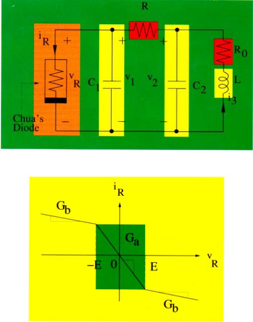
Fig. 3. (a) Chua's oscillator. (b) Chua's diode.
2805. Downloaded from www.worldscientific.com |
02/14/13. For personal use only. |
Chaos 1997.07:2789- |
by 128.73.53.214 on |
Int. J. Bifurcation |
|
2794 T. Yang & L. O. Chua |
|
|
|
|
|
|
|
|
|
|
|
|
|
||
where f( ) is the nonlinear characteristics of Chua's |
We use a continuous n-shift cipher to spread the |
||||||||||||||
diode given by |
chaotic signal generated by a Chua's circuit. |
The |
|||||||||||||
1 |
(Ga − Gb)(jv1 + Ej − jv1 − Ej) |
n-shift cipher is given by |
|
|
|
|
|||||||||
f(v1) = Gbv1 + |
|
|
|
|
|
|
|
|
|
|
|
|
|
|
|
2 |
|
|
|
|
|
|
|
|
|
|
|
|
|
||
(2) |
x(t) = e(p(t)) |
|
|
|
|
|
|
|
|
||||||
and E is the breakpoint voltage of Chua's diode. |
= f1 |
(: : : f1 |
(f1 |
(p(t); p(t)); p(t)); : : : ; p(t)) |
(3) |
||||||||||
The corresponding circuit is shown in Fig. 3. |
| |
|
|
{z |
|
|
} |
| |
|
{z |
|
} |
|
||
|
|
|
n |
|
|
|
|
n |
|
|
|||||
(a)
(b)
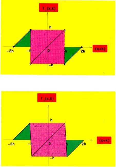
Fig. 4. Nonlinear function used in continuous shift cipher. (a) The ideal model. (b) The practical implementation.

2805. Downloaded from www.worldscientific.com |
02/14/13. For personal use only. |
Chaos 1997.07:2789- |
by 128.73.53.214 on |
Int. J. Bifurcation |
|
Chaotic Digital CDMA Communication Systems 2795
where h is chosen such that p(t) lies within (−h; h). f1( ; ) is a nonlinear function
1 |
> |
(x + k) + 2h; |
2h (x + k) |
h |
|
− |
|
||
|
> |
|
−h < (x + k) < h− |
|
|
< |
|
|
|
f (x; k) = |
8 |
(x + k); |
(4) |
|
|
> |
|
|
|
|
: |
|
h (x + k) 2h : |
|
|
>(x + k) − 2h; |
|
||
This function is shown in Fig. 4(a). Since the \jump-type" break points in Fig. 4(a) cannot be implemented in a practical circuit, what we need is the continuous version of this characteristics shown in Fig. 4(b). In this case, f1( ; ) is given by
|
|
> |
|
|
|
|
|
|
|
|
|
>8 h −h (x + k) + 2h; |
|||||||
|
|
> |
|
|
h |
|
|
|
|
|
|
> |
|
|
|
|
|
|
|
|
|
> |
|
|
|
|
|
|
|
|
|
> |
− |
|
|
|
|||
|
|
> |
|
|
|||||
|
|
> |
|
|
|
|
|
|
|
|
|
> |
|
|
|
|
|
|
|
|
|
> |
|
|
|
|
|
|
|
|
|
> |
|
|
|
|
|
|
|
|
|
> |
|
|
h |
|
|
||
|
|
> |
|
|
|
(x + k + h); |
|||
|
|
> |
|
|
|
|
|
|
|
|
|
> |
|
|
|
|
|
|
|
|
|
> h |
|
|
|
||||
|
|
> |
|
|
− |
|
|
|
|
|
|
< |
|
|
|
|
|
|
|
f |
(x; k) = |
> |
|
|
|
|
(x + k); |
||
1 |
|
> |
|
|
|
|
|||
|
|
> |
|
|
|
|
|
|
|
|
|
> |
− |
|
− |
|
|||
|
|
> |
|
||||||
|
|
> |
|
|
|
|
|
|
|
|
|
> |
|
|
|
|
|
|
|
|
|
> |
|
|
|
|
|
|
|
|
|
> |
|
|
|
|
|
|
|
|
|
> |
|
|
h |
|
|
|
|
|
|
> |
|
|
h |
(x + k |
|
h); |
|
|
|
> |
|
|
|
|
|
|
|
|
|
> |
|
|
|
|
|
|
|
|
|
> |
|
|
|
|
|
|
|
|
|
> h |
|
|
|
− |
|||
|
|
> |
|
|
|
|
|
|
|
|
|
> |
|
|
− |
|
|
|
|
|
|
> |
|
|
|
|
|
|
|
|
|
> |
|
|
|
|
|
|
|
|
|
> |
|
|
|
|
|
|
|
|
|
: |
|
|
|
|
(x + k) 2h; |
||
|
|
> |
|
|
|
|
|||
In our (CD)2MA systems, we choose the seed signal p(t) as the voltage v1(t) of Chua's circuit. Since we choose h = 1 V, p(t) is a normalized version of v1(t). Before we use the output of the n-shift function as the spreading carrier, we have to test its statistical properties. In our (CD)2MA systems, the following parameters are used: C1 = 5:56 nF, C2 = 50 nF, G = 0:7 mS, L = 7:14 mH, Ga = −0:8 mS, Gb = −0:5 mS, E = 1 V, R0 = 0 Ω and= 0:01. Given this set of parameters, Chua's circuit has a double-scroll attractor.
There are many tests that can be used to help establish the random characteristics of a signal [Knuth, 1981]. In this paper, we use two frequency tests: The 2 test and the Kolmogorov-Smirno (K-S) test. See [Knuth, 1981] for details about both the tests. They are used to verify that the signal is uniformly distributed.
For the 2 test, the range of x(t) is divided into 51 intervals. Our expectation is an equal number of observations in each interval. Thus the2 values computed on each sample will be expected to follow a 2 distribution with 50 degrees of freedom.
For the K-S test, K+ and K− are computed for each sample of x(t). The values are expected to be Kn-distributed, where n is the number of samples in the sampled x(t). In our simulations, n = 105 and the sampling interval is 10−7 s.
−2h (x + k) −h −
−h − (x + k) < −h +
−h + (x + k) < h − |
(5) |
|
h − (x + k) < h +
h + (x + k) 2h :
The following tests which were based on 2- tests are also used.
Serial test: In the sequences of sampled x(t), we want pairs of successive numbers to be uniformly distributed in an independent manner. To carry out the serial test, we simply count the number of times that the sampled pair (x(2j); x(2j+1)) fall in di erent regions of the plane [−1; 1] [−1; 1]. We split the interval [−1; 1] into d subintervals and code each of them by an integer from 1 to d. When x(2j) falls into a subinterval, we use the code of this subinterval, an integer Y2j, to represent it. This kind of coding system is also used in the other tests. To carry out the serial test, we simply count the number of times that (Y2j; Y2j+1) = (q; r) occurs, for 1 q; r d. And the 2-test is applied to these k = d2 categories with probability d12 for each category. We chose d = 8. The sequence of block should have a length 5d2.
Gap test: This test is used to test the length of \gaps" between occurrences of Yj in a certain range. If and are two real numbers with 0 < < d, we want to consider the lengths of the consecutive subsequences Yj; Yj+1; : : : ; Yj+r in which Yj+r lies between and but the other Y 's do not. In this test, we chose d = 9.
2805. Downloaded from www.worldscientific.com |
02/14/13. For personal use only. |
Chaos 1997.07:2789- |
by 128.73.53.214 on |
Int. J. Bifurcation |
|
2796 T. Yang & L. O. Chua
Poker test: The classical poker test considers n group of ve successive integers (Y5j; Y5j+1, Y5j+2; Y5j+3, Y5j+4) for 0 j < n, and observes which of the following ve categories is matched by each quintuple: 5 di erent, 4 di erent, 3 di erent, 2 different and 1 di erent.
In general we can consider n groups of k successive numbers, and we can count the number of k-tuples with r di erent values. A 2-test is then made, using the probability
|
|
k |
|
pr = |
d(d − 1) dk(d − r + 1) |
( r ) |
(6) |
( )
k
that there are r di erent. r is a Stirling number
[Halls et al., 1993]. In this case, we chose d = 9. Table 1 lists the test results of x(t) with di er-
ent initial conditions with 10-shift cipher function. In Table 1, when a test result is between 0:01 and 0:99, it denotes that x(t) can be viewed as a good pseudo-random sequence. The bold face numbers in Table 1 denote the test results which do not belong to good pseudo-random sequences. Since there are only two test results belonging to the \bad" pseudo-random cases, we conclude that the randomness of x(t) is good enough for designing spreading carriers. And we can see that this randomness is independent of the initial condition. This initial condition independent property can be used to simplify the hardware of mobile stations because we only need to give di erent initial conditions to each mobile station for generating its spreading carrier. Since these tests are used in testing the randomness of sequences for cryptographic
purposes, we can conclude that a good pseudorandom sequence should have a very narrow autocorrelation function.
4.Impulsive Synchronization of Chua's Circuits in (CD )2MA
The idea of applying impulsive synchronization to (CD)2MA is inspired by the fact that every mobile station of a CDMA system has a clock signal to make the receiver work autonomously once the clock signal is synchronized with that of the transmitter. The di erence between impulsive synchronization and continuous synchronization is that, in the former, once the synchronization is achieved the receiver can work autonomously for a given time duration. This is achieved by sending synchronizing impulses to the receiver. We should send synchronizing impulses to the receiver at a given frequency because the noise and parameter mismatches between the chaotic systems in the transmitter and the receiver will soon desynchronize both. For this reason, in the (CD)2MA system we need an overhead channel to transmit synchronizing impulses.
In this section, we study the impulsive synchronization of two Chua's oscillators. One of the Chua's oscillators is called the driving system and the other is called the driven system. In an impulsive synchronization con guration, the driving system is given by Eq. (1). Let xT = (v1 v2 i3), then we can rewrite the driving system in Eq. (1) into the form
x = Ax + (x) |
(7) |
Table 1. Results of di erent statistical tests of chaotic spreading carriers when di erent initial conditions are used.
|
v1(0) = −0:204 V |
v1(0) = 1:568 V |
v1(0) = 0:1 V |
v1 = −2:56 V |
|
v2(0) = 0:045 V |
v2(0) = −0:741 V |
v2(0) = 2:515 V |
v2 = −1:349 V |
|
i3(0) = 1:561 mA |
i3(0) = 2:301 mA |
i3(0) = −1:901 mA |
i3 = −2:002 mA |
2 Test |
0.021 |
0.013 |
0.054 |
0.07 |
K-S Test, K+ |
0.011 |
0.044 |
0.034 |
0.009 |
K-S Test, K− |
0.034 |
0.025 |
0.029 |
0.012 |
Serial Test |
0.008 |
0.067 |
0.045 |
0.074 |
Gap Test |
0.055 |
0.054 |
0.082 |
0.03 |
Poker Test |
0.063 |
0.019 |
0.018 |
0.06 |
|
|
|
|
|

2805. Downloaded from www.worldscientific.com |
02/14/13. For personal use only. |
Chaos 1997.07:2789- |
by 128.73.53.214 on |
Int. J. Bifurcation |
|
Chaotic Digital CDMA Communication Systems 2797
where |
|
|
|
|
|
|
|
|
|
|
|
|
|
|
|
|
B |
−G=C1 |
G=C1 |
|
0 |
|
C |
|
|
B |
f(v1)=C1 |
C |
|
|
|
A = |
0 |
G=C |
G=C |
1=C |
1 |
; |
(x) = |
0− |
0 |
1 |
: |
(8) |
|||
|
@ |
0 |
− |
1=L |
− |
R0 |
|
A |
|
|
@ |
0 |
A |
|
|
|
B |
|
|
=LC |
|
|
B |
C |
|
|
|||||
Then the driven system is given by |
|
|
|
_ |
(9) |
|
x~ = Ax~ + (x~) |
|
T |
~ |
|
where x~ |
= (~v1; v~2; i3) are the state variables of |
|
the driven system.
At discrete instants, i; i = 1; 2; : : : , the state variables of the driving system are transmitted to the driven system and then the state variables of the driven system are subject to jumps at these instants. In this sense, the driven system is described
by an impulsive di erential equation |
|
|||||
_ |
A |
x~); |
t = |
|
|
|
(x~ = |
i; ; : : : |
|
||||
|
x~ + (B |
; |
i 6 |
(10) |
||
x~jt= i = − |
e |
= 1 2 |
|
|||
where B is a 3 3 matrix, and eT = (e1; e2; e3) =
− − −~
(v1 v~1; v2 v~2; i3 i3) is the synchronization error. If we de ne
Salmasi, 1991; Lee, 1991; Pickholtz, 1991]. In this paper, we use the method presented in [Gilhousen et al., 1991] to estimate the capacity of (CD)2MA. Due to the structural di erences between CDMA and (CD)2MA, we revise the method presented in [Gilhousen et al., 1991], which was originally proposed for CDMA, to cope with our (CD)2MA schemes.
As in CDMA, we focus on the reverse link capacity because the forward link uses coherent demodulation by the pilot carrier, which is being tracked, and since its multiple transmitted signals are synchronously combined, its performance will be superior to that of the reverse link.
The estimate of the capacity of a CDMA system depends on the model of the whole CDMA system. To model a CDMA system, the following factors should be considered.
Ψ(x; x~) = (x) − (x~)
0−f(v1)=C1 + f(~v1)=C1 1
= |
B |
0 |
C |
(11) |
B |
C |
|||
|
@ |
0 |
A |
|
|
|
|
|
then the error system of the impulsive synchronization is given by
(
e = Ae + Ψ(x; x~); |
t 6= i |
: (12) |
ejt= i = Be; |
i = 1; 2; : : : |
|
The conditions for the asymptotic stability of impulsive synchronization can be found in [Yang & Chua, 1997b]. The results in [Yang & Chua, 1997b] also show that the impulsive synchronization is robust enough to additive channel noise and the parameter mismatch between the driving and driven systems.
5.Considerations for Investigating the Capacities of CDMA and (CD )2MA
Several approaches to estimate cellular CDMA capacity have been developed [Gilhousen et al., 1991;
5.1. Interference
We usually approximate the interference to a given user from all other multiple access users by a Gaussian process [Ulloa et al., 1995]. As with any digital communication system, spread spectrum or not, there are four components of the demodulator output:
the desired output,
the inter-chip interference components, which is usually called inter-symbol interference for nonspread digital demodulation,
the component due to background noise, and
the other-user interference components,
In a CDMA system, the interference from the other users is much stronger than that from the noise.
5.2. Power control
It is well-known that one of the most serious problems faced by a DS CDMA system is the multi-user interference. Because all users are transmitting in the same frequency band and the cross-correlatons of the codes are rarely zero, the signal-to-inference ratio, and hence the performance, decreases as the number of users increases, which shows that DS
2805. Downloaded from www.worldscientific.com |
02/14/13. For personal use only. |
Chaos 1997.07:2789- |
by 128.73.53.214 on |
Int. J. Bifurcation |
|
2798 T. Yang & L. O. Chua
CDMA is an interference-limited, rather than a noise-limited, system.
An e ect known as the \near-far" e ect plays an especially important role when considering multi-user interference. The near-far e ect can be explained by considering the reverse link. Due to the path-loss law (which implies that the received power decreases as the transmitter-receiver distance increases), a close user will dominate over a user located at the boundary. In order to overcome the near-far e ect, power control can be used.
The propagating loss is generally modeled as the product of the mth power of distance r and the log-normal component representing shadowing losses. This model represents slowly varying losses, even for users in motion, and applies to both reverse and forward links. The more rapidly varying Rayleigh fading losses are not included here. Thus, for a user at a distance r from a base station, attenuation is proportional to
(r; ") = rm10"=10 |
(13) |
where " is the decibel attenuation due to shadowing, with zero mean and standard deviation . Experimental data [Lee, 1989] suggest the choices of m = 4 for the power law and = 8 dB for the standard deviation of ".
Power control can be established by letting the base station continuously transmit a pilot signal that is monitored by all mobile stations. According to the power level detected by the mobile station, the mobile station adjusts its transmission power. In a practical power control system, power control errors occur [Jansen & Prasad, 1995], implying that the average received power at the base station may not be the same for each user signal.
5.3. Multi-path propagation
In terrestrial communication, the transmitted signal is reflected and refracted by di erent smooth or rough surfaces and di erent objects, so that it is replicated at the mobile station with di erent time delays. This is called multi-path propagation. It can be quite severe in urban areas or within a building. Di erent paths arrive at di erent amplitudes and carrier phases. The path amplitude depend on the relative propagation distances and the reflective or refractive properties of the terrain or buildings. In many cases, particularly in a con ned area, each distinguishable multi-path component will be
actually the linear combination of several indistinguishable paths of varying amplitudes. Since these will add as random vectors, the amplitude of each term will appear to be Rayleigh-distributed, and the phase uniformly distributed. This is the most commonly accepted model [Viterbi, 1995].
Since two code sequences with a relative delay of more than two chip durations usually have a low correlation value compared to the fully synchronized situation, DS CDMA o ers the possibility to distinguish between paths with a relative delay of more than two chip durations. This is called the inherent diversity of DS CDMA, implying that it is possible to resolve a number of paths separately using only one receiver. This property makes DS CDMA suitable for applications in mobile radio environments, which are usually corrupted with severe multi-path e ects.
The multi-path fading channel for the kth mobile station is characterized by a set of its low-pass equivalent complex-values impulse responses
(hk(t) = |
L |
akl (t − kl) exp(−j kl))K |
(14) |
|
l=1 |
k=1 |
|
|
X |
|
where K denotes the number of the active users. Here we assume that every link has a xed number L of resolvable paths. The path gains faklgLl=1,
path delays f klgLl=1, and path phases f klgLl=1 are three random variables. For a given k, faklgLl=1 is
modeled as the set of the independent Rayleigh random variables whose probability density functions are given by:
p( k) = |
2 ke− k2= kr2 |
; > 0; k = 1; 2; : : : ; L : |
|
2 |
|||
|
|
||
|
kr |
|
|
|
|
(15) |
We suppose that the L multipath components are all Rayleigh of equal average strength, so that
2 |
= 2 |
; for all k = 1; 2; : : : ; L : |
(16) |
kr |
r |
|
|
According to [Wu et al., 1995], we choose r = 4 dB. The f klgLl=1 are mutually independent and uniformly distributed over [ 1; 2], and the f klgLl=1 are independent uniform random variables over [0; 2 ), all of which are also statistically independent of each other. In this paper, we choose L = 5, and 1 and 2 are chosen in the corresponding simulation which will be presented later.