

Allen and Holberg - CMOS Analog Circuit Design |
Page I.0-1 |
I. INTRODUCTION
Contents
I.1 Introduction
I.2 Analog Integrated Circuit Design
I.3 Technology Overview
I.4 Notation
I.5 Analog Circuit Analysis Techniques
Allen and Holberg - CMOS Analog Circuit Design |
Page I.0-2 |
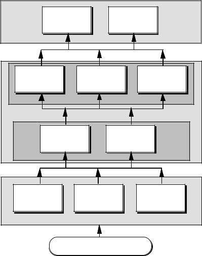
Organization
Chapter 10
D/A and A/D
Chapter 11
Converters
Analog Systems
SYSTEMS |
|
|
Chapter 7 |
Chapter 8 |
Chapter 9 |
CMOS |
Simple CMOS |
High Performance |
Comparators |
Opamps |
Opamps |
COMPLEX |
|
|
CIRCUITS |
|
|
Chapter 5 |
Chapter 6 |
|
CMOS |
|
CMOS |
Subcircuits |
Amplifiers |
|
SIMPLE |
|
|
Chapter 2 |
Chapter 3 |
Chapter 4 |
CMOS |
CMOS Device |
Device |
Technology |
Modeling |
Characterization |
DEVICES |
|
|
|
Introduction |
|

Allen and Holberg - CMOS Analog Circuit Design |
Page I.2-1 |
I.1 - INTRODUCTION
GLOBAL OBJECTIVES
•Teach the analysis, modeling, simulation, and design of analog circuits implemented in CMOS technology.
•Emphasis will be on the design methodology and a hierarchical approach to the subject.
SPECIFIC OBJECTIVES
1.Present an overall, uniform viewpoint of CMOS analog circuit design.
2.Achieve an understanding of analog circuit design.
•Hand calculations using simple models
•Emphasis on insight
•Simulation to provide second-order design resolution
3.Present a hierarchical approach.
•Sub-blocks → Blocks → Circuits → Systems
4.Examples to illustrate the concepts.
Allen and Holberg - CMOS Analog Circuit Design |
Page I.2-1 |
I.2 ANALOG INTEGRATED CIRCUIT DESIGN
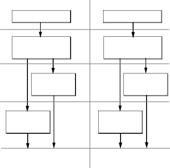
ANALOG DESIGN TECHNIQUES VERSUS TIME
FILTERS
Passive RLC circuits
1935-1950
Active-RC Filters Requires precise definition of time constants (RC products)
1978
Switched Capacitor
Filters
Requires precise C ratios and clock
1983
Continuous Time
Filters
Time constants are adjustable
AMPLIFICATION
Open-loop amplifiers
Feedback Amplifiers
Requires precise definition of passive components
Switched Capacitor
Amplifiers
Requires precise C ratios
Continuous Time
Amplifiers
Component ratios are adjustable
1992
? |
Digitally assisted analog circuits |
? |
|
Allen and Holberg - CMOS Analog Circuit Design |
Page I.2-2 |
DISCRETE VS. INTEGRATED ANALOG CIRCUIT DESIGN
Activity/Item |
Discrete |
Integrated |
Component Accuracy |
Well known |
Poor absolute accuracies |
Breadboarding? |
Yes |
No (kit parts) |
Fabrication |
Independent |
Very Dependent |
Physical |
PC layout |
Layout, verification, and |
Implementation |
|
extraction |
Parasitics |
Not Important |
Must be included in the |
|
|
design |
Simulation |
Model parameters well |
Model parameters vary |
|
known |
widely |
Testing |
Generally complete |
Must be considered |
|
testing is possible |
before the design |
CAD |
Schematic capture, |
Schematic capture, |
|
simulation, PC board |
simulation, extraction, |
|
layout |
LVS, layout and routing |
Components |
All possible |
Active devices, |
|
|
capacitors, and resistors |
Allen and Holberg - CMOS Analog Circuit Design |
Page I.2-3 |
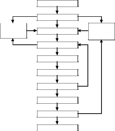
THE ANALOG IC DESIGN PROCESS
Comparison with design specifications
Conception of the idea
Definition of the design 
Implementation
Simulation
Physical Definition
Physical Verification
Parasitic Extraction
Fabrication
Testing and Verification 
Product
Comparison with design specifications
Allen and Holberg - CMOS Analog Circuit Design |
Page I.2-4 |
COMPARISON OF ANALOG AND DIGITAL CIRCUITS
Analog Circuits |
|
Digital Circuits |
|
|
Signals are continuous in amplitude |
Signal |
are |
discontinuous |
in |
and can be continuous or discrete in |
amplitude and time - binary signals |
|||
time |
have two amplitude states |
|
||
Designed at the circuit level |
Designed at the systems level |
|
||
Components must have a continuum |
Component have fixed values |
|
||
of values |
|
|
|
|
Customized |
Standard |
|
|
|
CAD tools are difficult to apply |
CAD tools have been extremely |
|||
|
successful |
|
|
|
Requires precision modeling |
Timing models only |
|
||
Performance optimized |
Programmable by software |
|
||
Irregular block |
Regular blocks |
|
|
|
Difficult to route automatically |
Easy to route automatically |
|
||
Dynamic range limited by power |
Dynamic range unlimited |
|
||
supplies and noise (and linearity) |
|
|
|
|
Allen and Holberg - CMOS Analog Circuit Design Page I.3-1
I.3 TECHNOLOGY OVERVIEW
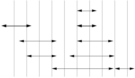
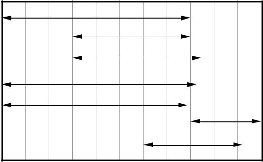
BANDWIDTHS OF SIGNALS USED IN SIGNAL PROCESSING APPLICATIONS
|
|
|
|
|
|
|
|
Video |
|
|
|
|
|
|
|
|
|
|
|
|
|
Acoustic |
|
|
|
|
|
|
|
Seismic |
|
|
|
|
|
imaging |
|
|
|
|
|
|
|
|
|
Sonar |
|
|
|
Radar |
|
|
|
|
|
|
|
|
|
Audio |
|
AM-FM radio, TV |
|
|
|
|
|||
|
|
|
|
|
|
Telecommunications |
Microwave |
|
|
||||
|
|
|
|
|
|
|
|
|
|
|
|
|
|
1 |
10 |
100 |
1k |
10k |
100k |
1M |
10M |
100M |
1G |
10G |
100G |
||
|
|
|
|
|
|
Signal Frequency (Hz) |
|
|
|
|
|
||
Signal frequency used in signal processing applications.
Allen and Holberg - CMOS Analog Circuit Design |
Page I.3-2 |
BANDWIDTHS THAT CAN BE PROCESSED BY PRESENT-
DAY TECHNOLOGIES
BiCMOS
Bipolar analog
Bipolar digital logic
MOS digital logic
MOS analog
Optical
GaAs
1 |
10 |
100 |
1k |
10k |
100k |
1M |
10M |
100M |
1G |
10G |
100G |
|
|
|
|
|
Signal Frequency (Hz) |
|
|
|
|
||
Frequencies that can be processed by present-day technologies.
Allen and Holberg - CMOS Analog Circuit Design |
Page I.3-3 |
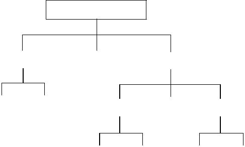
CLASSIFICATION OF SILICON TECHNOLOGY
Silicon IC Technologies
Bipolar |
|
Bipolar/MOS |
|
|
|
|
MOS |
||
|
|
|
|
|
|
|
|
|
|
Junction |
|
Dielectric |
|
|
|
PMOS |
|
|
|
|
CMOS |
|
|
NMOS |
|||
Isolated |
|
Isolated |
|
|
(Aluminum |
|
||
|
|
|
|
|
|
Gate) |
|
|
|
|
|
|
|
|
|
|
Aluminum |
|
Silicon |
|
Aluminum |
|
Silicon |
gate |
|
gate |
|
gate |
|
gate |
|
|
|
|
|
|
|