

Статьи на перевод PVDF_P(VDF-TrFE) / Fabrication, characterization and modeling of PVDF based organic IR-sensors for human body recognition
.pdfFabrication, Characterization and Modeling of PVDF based organic IR-Sensors for Human Body Recognition
Scheipl G., Zirkl M., Stadlober B., Groten J., Jakopic |
Sawatdee A., Bodö P., Andersson P. |
G., Krenn J.R. |
Acreo AB |
Institute of nanostructured Materials and Photonics |
ICT Research AB |
Joanneum Research |
602 21 Norrköping, Sweden |
8160 Weiz, Austria |
|
gregor.scheipl@joanneum.at |
|
Abstract - Within this work a cost-effective thin film-sensor- technology based on PVDF-TrFE polymers for detection of ambient changes of temperature has been developed. A wetchemical fabrication routine for obtaining ferroelectric thin films has been developed leading to a gammabutyrolactone based sol-gel process. The suitability of the synthesized material with respect to its usage as IR-sensing layer has been evaluated by vibrational spectroscopy and various electrical characterizations. In a second step, the adaptation of the lab scale routines for large area printing techniques on flexible substrates and their influence on the overall sensor performance and stability has been developed and tested. For simplifying the design process of adequate sensors used in different industrial applications, a mathematical model based on the heat distribution in a multilayer sensor system has been assessed and revised by experiments.
I.INTRODUCTION
In the field of organic electronics a lot of efforts towards low-cost production and integration of organic electronic devices on flexible substrates have been made during the last decades [1], [2] thus making them suitable for direct integration on packaging, smart cards, displays, and every day items. Concerning the latter innovative flexible sensors would enable diverse objects to see, hear, taste, smell and feel. Thereby, more and more applications emerge nowadays and in the future, realizing advanced interactions of humans and objects. Successful and satisfying communication between objects and human beings often relies on the object’s capability to recognize tactile information and distinguish humans from inanimate objects by sensing temperature and pressure and recognize their modulations in the ambience. In this context we have developed a large-area process for the fabrication of ferroelectric, organic sensor elements based on a PVDF-TrFE copolymer capacitor on flexible substrates that is applicable with different printing methods.
II.SAMPLE PREPERATION
A.Ferroelectric sensor material
PVDF is a well known semi-crystalline dipole electret,
composed of ferroor paraelectric crystallites embedded in
amorphous regions with a quasi permanent dipole orientation polarization and Maxwell-Wagner compensation charges at the interface between amorphous and crystalline regions [3]. According to crystallization conditions, PVDF can crystallize into three structures: form I (β-type crystal with planar zig-zag conformation), form II (α-type crystal with TGTG¯ conformation) and form III (γ-type crystal with the TTTGTTTG¯ conformation) [3]. When PVDF crystallizes from melt, it normally forms the paraelectric α-phase, but adding different amounts of TrFE (trifluorethylene) is known to stabilize the ferroelectric ß-phase. Within this work samples are discussed which are based on a solution containing P(VDF:TrFE) in a ratio of 70:30 mol%. This composition emerged to be the most promising way to obtain highly crystalline, sufficiently flat, ferroelectric thin films by using a low-temperature spin-on process. Resulting samples have been analyzed using FTIR-spectroscopy verifying that the used copolymer composition leads to the formation of ferroelectric form I polymer layers (figure 1).
B. Methods for fabricating the ferroelectric layer
50ml of у-butyrolactone is heated up to 180°C using a reflux condenser to avoid solvent evaporation. A known amount of P(VDF-TrFE) pellets with a VDF:TrFE composition of 70:30 is added and dissolved under conditions of heating and agitating. The solution is kept at this temperature for about two hours. Afterwards the solution is cooled down to room temperature for gelation [3]. For preparing thin films, three different methods have been applied: The first is a low temperature spin-on process. Glass or flexible PET films are used as a substrate. Aluminum layers with a thickness of 60nm are e-beam evaporated on the substrate serving as a bottom electrode onto which the sol is spin coated. Subsequently a calcination step is carried out at 110°C, which increases the crystallinity of the PVDF-TrFE thin films. The samples are kept at this temperature for 5 hours and then slowly cooled down to room temperature. Finally 80 nm thick top electrodes are deposited by e-beam evaporation of aluminum. As an IR-absorbing layer carbon is directly applied on the top electrodes. The other two deposition processes used for the fabrication of P(VDF:TrFE) thin films are screen printing and bar coating, respectively. For
978-1-4244-5335-1/09/$26.00 ©2009 IEEE |
1252 |
IEEE SENSORS 2009 Conference |

Figure 1. IR-spectra of polymer layers with varying PVDF:TrFE compositions. It can be seen that a TrFE content below15 mol% insufficiently supports the formation of the ferroelectric form I PVDF (typical IR-modes of the non-ferroelectric form II are indicated by the arrows).
screen printing a PET-foil with 1µm thick aluminium covering is used as a substrate on which the P(VDF:TrFE) gel is deposited via a stencil on the substrate. The attached stencil forms open areas of mesh that transfer ink as a sharp-edged image onto the Al/PET-foil substrate. A roller is moved across the screen stencil, forcing or pumping the gel in the threads of the woven mesh in the open areas. The thickness of the resulting layers varies between 5 µm and 8 µm. After the printing process the sample is kept at room temperature for about 10 minutes and subsequently exposed to a calcination step at 110°C for 75 minutes. As top electrode screen-printed carbon, screen-printed PEDOT or evaporated aluminium is used. The third method for printing sensor stripes is bar coating which was carried out using a “Byk Gardner Automatic film applicator”. The substrate is the same Al/PET foil which was used for screen printing. Wire-wound rods with a specified wet film thickness from 25 to 100 µm are used to deposit the gel on the substrate. The resulting layer thicknesses obtained with a drawing speed of 50 mm/sec were ranging from 1-6 µm. Following process steps are done in the same way as described for screen printing. There was no need for surface treatment or cleaning processes of the Al/PET-foil substrate, which is a big advantage.
III.PYROELECTRIC CHARACTERIZATION
Varying sensor stripes have been fabricated based on different solution composition (12, 15 and 18 wt% of P(VDF:TrFE) 70:30). Sensor stripes, different electrodes of alumina, carbon paste or PEDOT and substrates (glass or PET foil) have been evaluated with respect to their electric properties. As reference material commercially available PVDF-sheets (Kureha) have also been used for the fabrication of substrate-free stand alone sensor stripes.
For the usage as transducer material, the crystalline domains must be aligned with respect to their electrical dipoles. Therefore a stepwise poling procedure above the coercive field strength of the ferroelectric material (55 MV/m)
is applied using a Keithley 6517A electrometer. The step-wise poling is performed by a series of pulses lasting several minutes, and with increasing height. The pulse width is 4 min and the interval between two pulses is 2 min. The maximum applied field strength is 100 V/µm-1, with a constant increase of 20 V/µm- 1[4].
The setup for the pyroelectric measurements consists of a Keithley 6221 function generator triggering a Newport 500B laser diode driver, an infrared laser diode with an emission of 70 mW at a wavelength of 808 nm and an EG&G Lock-In Amplifier with an input impedance of 100 MΩ.
IV. RESULTS
The frequency dependent pyroelectric current and voltage outputs of spin-coated pyroelectric sensors with different areas are shown in figure 2. Similar curves are also obtained for printed PVDF-TrFE based sensors. The impinging laser beam always excites a constant area of 3 mm2 being much smaller than the overall area of the sensor. The overall sensor area is decreased stepwise by successively cutting the connecting lines between the circular sensor fields (see figure 2 bottom). Accordingly the parasitic capacitance of the sensor is decreased without decreasing the excited area.
As is observed in figure 2 the parasitic capacities are decreasing the voltage output though are not effecting the current generated by the laser excitation. This is due to the fact that the pyroelectric current varies as
V = I |
R |
(1) |
1+ω2 R2C2 |
with R and C being impedance and capacitance of the equivalent circuit (thus also including capacitance and impedance of the measurement circuit). According to (1) the voltage response varies as I R below and I/ωC above the cutoff frequency. The cut-off frequency is determined by the RCtime constant of the whole equivalent circuit. The generated pyroelectric current I can be described as
|
|
(2) |
I = pAωT |
||
with p being the pyroelectric coefficient, A being the excited area and T being the average temperature of the pyroelectric layer.
From (1) and (2) it becomes clear that the current response is independent of the parasitic capacitance whereas the voltage response is decreased.
The overall frequency behaviour, the influence of sensor geometry, parasitic capacitance and impedance, absorption coefficients of the top electrodes, pyroelectric sensitivity of the sensor layer and influences of fabrication processes have been evaluated and verified using mathematic modeling of the electric measurements. The structure of a pyroelectrical sensor is crucial for its thermal behavior.
The main field of interest is in the thermal wave flow through the multilayer sequence of the sensor. In this regard the temperature change induced by the laser modulation is calculated from the heat conduction model following the approach of D. Setiadi et al. [5]. Out of this reason the
1253
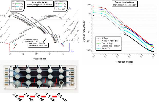
Figure 2. The influence of parasitic capacities on the pyroelectric sensor output and its mathematically assessment (solid lines) are shown (top). The overall sensor area is decreased stepwise by successively cutting the connecting lines between the circular sensor fields at a constant area of excitation (bottom). Additional explanations are given in the text.
calculation is limited to a one dimensional equation. The thermal diffusion equation for each layer is
∂Tn (x,t) |
= |
δn |
|
∂²Tn (x,t) . |
(3) |
c d |
|
||||
∂t |
|
n |
∂x² |
|
|
|
|
n |
|
|
All layers possess heat conductivity δn (W.m-1.K-1), a specific heat cn (J.kg-1.K-1) and a density dn (kg.m-3) with n
being the layer number. Boundary conditions for an interface between two adjacent layers and the boundary conditions of the back side and the front side have to be considered in order to solve this equation. The final solution for the average temperature of the pyroelectric layer can be written as
|
(t) = |
ηP1 |
(a (eα2 w2 |
−1) +b (1−e−α2 w2 |
)) . (4) |
|
Τ |
||||||
|
||||||
|
|
2 |
2 |
|
||
|
|
α2w2 |
|
|
||
Here the coefficients a2 and b2 are frequency dependent matrix functions. P is the excitation power, w2 is the thickness of the pyroelectric layer and η is the absorption coefficient. Based on (4) the pyroelectric current can be modeled according to (2) as well as the voltage response (according to (1)). Input parameters for the modeling are the sensor geometry including layer thicknesses and excitation area, the parasitic capacitance and impedance, literature values of the material parameters and the pyroelectric and the absorption
Figure 3. Comparison of different electrode materials. The influence on the volage response has been evaluated on stand-alone sensors based on commercially available PVDF sheets (Kureha) and can be addressed to the absorption characteristics of these electrode materials.
coefficient, both determined by independent measurements. The resulting simulated response curves are also included in figure 2 as solid lines. The excellent correspondence to the experimental data points fully verifies the theoretical model of the multilayer sensor and the simulation routine. As expected the current response is not influenced by the parasitic capacities whereas the voltage response decreases continuously with increasing parasitic capacitance.
For a better integration in industrial production, printed electrodes have been evaluated regarding their chemical and physical properties and their influence on the pyroelectric material. Therefore carbon and PEDOT electrodes have been printed on one or both sides of commercially available PVDF sheets. In addition, also aluminium electrodes were evaporated on similar substrates. On some of the aluminium electrodes a graphite absorber layer was applied.
The resulting voltage response of the pyroelectric sheets is shown in figure 3 – thus comparing the influence of different types of electrodes on the pyroelectric sensitivity. It is obvious, that the evaporated aluminium electrodes with absorber layer have the highest response in the low frequency limit but the printed carbon electrodes also exhibit very good response. A big advantage of carbon electrodes is their good absorbance in the infrared region therefore economizing on an additional absorber structure. The sensors based on pure aluminium electrodes yield a smaller response due to the limited IR absorption of aluminium. The frequency dependence of the response is equivalent for all electrode materials. These findings are also consistent with printed PVDF-TrFE layers. However, in the latter case the influence of paste solvents and annealing temperatures on the pyroelectric layers is a little bit more pronounced than it is for the commercial films resulting in a larger difference between evaporated aluminium + absorber layers and printed carbon layers.
1254
V.CONCLUSION
Correlations between the phase formation of the polymorphic pyroelectric PVDF-TrFE copolymer and the copolymer composition have been investigated by ATR- FTIR-spectroscopy. With the most suitable polymer composition with respect to its thermal stability and phase formation (of the ferroelectric form I), various sensor elements have been fabricated, poled and measured. These sensors have been produced in lab scale format based on different solutions, electrode materials and substrates. Afterwards they have been tested with respect to their electric properties and pyroelectric sensitivities. The influence of absorbing electrodes, different sensor sizes and fabrication processes have been evaluated both experimentally as well as theoretically. The frequency dependent pyroelectric current and voltage outputs have been measured for numerous sensor layouts. Measurements and acquired data have been verified using mathematic modeling of the thermal wave flow through the multilayered sensor. Based on this model the observed beneficial influence of decreasing parasitic capacities on the voltage output of a sensor at decreased parasitic sensor areas was described correctly by the model. In addition, differences of the IRabsorption behavior of varying electrode materials as well as different material formulations for their usage in large area printing processes of pyroelectric sensors have also been evaluated. It turned out that the carbon-based printed electrodes are very well suited as electrodes for pyroelectric sensors both with respect to the good IR absorbance as well as due to their chemical and process compatibility with PVDFbased copolymer layers. The efforts regarding printing experiments for totally printed sensors will be intensified for
improving the printing process itself on the one hand and the influence of the printing process on the materials on the other hand.
ACKNOWLEDGMENT
Special thanks go to Dr. Martin Zirkl and to Dr. Barbara Stadlober for the professional assistance and to MSc. Anurak Sawatdee for printing the sensors and answering questions concerning the printing technique.
Thanks may also be addressed to the consortium of the 3PLAST EU-project for good collaboration as well as the EU for the funding of this project.
REFERENCES
[1]G. H. Gelnick, H. Edzer, A. Huitema, E. van Veenendaal and E. Cantatore, “Flexible active-matrix displays and shift registers based on solution-processed organic transistors”, Nature materials, 3, pp. 106110, 2004
[2]W. Weiping, X. Wei, H. Wenping and L. Yunqi, “Progresses in organic field-effect transistors and molecular electronics”, Frontiers of Chemistry in China, 1(4), pp. 357 -363, December
[3]M. Zirkl, B. Stadlober, G. Leising, “Synthesis of Ferroelectric Poly(Vinylidene Fluoride) Copolymer Films and their Application in Integrated Full Organic Pyroelectric Sensors“, Ferroelectrics, 353, pp. 173-185, 2007
[4]D. Setiadi, P.M. Sarro, P.P.L. Regtien, ”A 3 x 1 integrated pyroelectric sensor based on VDF/TrFE copolymer”, Sensors and Actuators, 52(A), pp. 103-109, 1996
[5]D. Setiadi and P.P.L. Regtien, ”Design of a VDF/TrFE copolymer-on- silicon pyroelectric sensor”, Ferroelectrics, 173, pp. 309-324, 1995
1255