

piston_damage
.pdfPiston damages
Description – assessment – causes
Damage assessment
Fuel flooding due to abnormal combustion always damages the oil film. This initially leads to a higher level of mixed friction and therefore increased wear in the piston ring area. The characteristic damage caused by unburned fuel does not arise until the oil film is destroyed by the fuel to such an extent that the piston is running without lubrication (see also point “3.2.3 Dry running damage due to lack of lubrication
caused by fuel flooding”). However, the increasingly ineffective lubrication results in high levels of wear on the piston rings, piston ring grooves and cylinder running surfaces.
In the initial stages the piston skirt is affected to a lesser degree, as it is continuously supplied with new oil
from the crankshaft drive which is still capable of providing lubrication. Once the abraded particles from the mov-
ing area of the pistons start to become more and more mixed with the lubricating oil and the lubricating oil starts to lose its load-bearing ability as a result of oil dilution, the wear will spread to all of the moving parts in the engine. This affects the crankshaft journals and piston pins in particular.
Possible causes for the da
•Fuel flooding due to faults in the mixture formation stage (gasoline/ petrol and diesel engines).
•Faults in the ignition system (gasoline/petrol engines).
•Insufficient compression pressure.
•Incorrect piston protrusion/overlap: The piston strikes against the cylinder head when the engine is running. On diesel engines with direct injection, the shocks and resulting vibrations cause uncontrolled injec-
tion of fuel from the injectors and thus fuel flooding in the cylinder (see also point “3.4.5 Impact marks on the piston crown”).
MSI Motor Service International |
Piston damages – Recognising and rectifying | 81 |

Piston damages
Description – assessment – causes
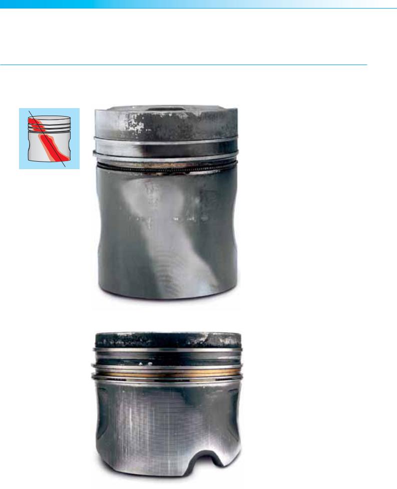
3.11.4Piston ring wear (soon after a major engine overhaul) (increased oil consumption)
Fig. 1
Description of the damage
The pistons display no signs of wear. Superficial inspection of the piston rings initially reveals no visible or measurable wear. However, closer inspection of
the rings reveals abnormal wear on the
oil-scraping ring edges, mostly on the bottom ring edge. A look at the enlarged image shows that the bottom ring edges have become almost frayed. Without resorting to an enlarged image, it is also
possible to detect this type of damage by touching the clearly sharp, burred edge of the ring (Fig. 1).
Damage assessment
High hydrodynamic forces arise between the running surfaces of the piston rings and the cylinder running surface as a result of the worn piston ring edges and the consequent formation of a so-called oil wedge (Fig. 2). The piston rings float on the oil film
during the upward/downward motion of the piston and are lifted slightly off the cylinder running surface. In this way, increased quantities of lubricating oil reach the combustion chamber where they are then burned.
Fig. 2
82 | Piston damages – Recognising and rectifying |
MSI Motor Service International |

Piston damages
Description – assessment – causes
Possible causes for the damage
This type of burring is caused if the piston rings are refitted in less than ideal conditions after the engine overhaul. The main reasons are insufficient or inappropriate end finishing of the cylinder. If diamonds or blunt honing stones are used for finish honing, burrs and elevations which are folded over in the direction of machining form on the cylinder wall. This bending over of metal peaks is referred to as the so-called “peak folding formation” and causes increased friction during the running-in phase, preventing oil from becoming deposited in the fine graphite veins (Fig. 3).
If these burrs are not removed in a subsequent machining process referred to as plateau honing, then this will result in premature wear at the piston ring edges during the runningin phase. The rings then take on the undesired duty of wearing away the folded peaks and cleaning the graphite veins. However, this leads to wear on the piston ring edges and the burrs described above. Judging from experience, burrs created in this way on the piston ring edge can only be run off in operation with great difficulty, if at all. The only practical solution is to replace the damaged piston rings.
As the first set of piston rings will have removed most of the disadvantageous edge layer on the cylinder running surface (the so-called “peak folding formation”) through wear, a second set of rings installed as replacement rings will encounter much better – if not normal – operating conditions. The oil consumption will return to normal levels after installing new piston rings. In many cases this is incorrectly attributed to poor material quality of the first set of piston rings, which of course is not the case.
Fig. 4 shows a microscopic enlargement through a section of the cylinder surface after honing the cylinder running surface. The bent-over peaks can be seen clearly. Fig. 5 shows the surface after plateau honing. The burrs and peaks have been mostly removed, and the graphite veins have been exposed. The piston rings will immediately encounter good conditions for running-in and should provide a long service life. Hone-brushing the surface to create the plateau finish delivers particularly good results.
For further information on this topic, please refer to our booklet “Honing of gray cast iron cylinder blocks” (see appendix)
Fig. 3
Fig. 4
Fig. 5
MSI Motor Service International |
Piston damages – Recognising and rectifying | 83 |
Piston damages
Description – assessment – causes
3.11.5 Asymmetric piston wear pattern (increased oil consumption)
Fig. 1
Description of the damage
In Fig. 1, the wear pattern of the piston over the entire piston height is asymmetrical on both sides. The piston
top land has been rubbed bare on the left-hand side of the piston above the piston pin bore (left-hand side of the picture), whereas stop marks are evident on the opposite side at the lower edge of the piston. The uppermost compression ring also displays an uneven wear pattern. Load-bearing, shiny surfaces alternate with darker, matt areas with a blue discoloration (tempering colours).
Fig. 2 also shows an example of a piston which has not run perfectly straight. However, in this case the main area which has been worn is on the lower right-hand edge of the piston around the cutout for the cooling oil nozzle, rather than around the piston top land.
Fig. 2
84 | Piston damages – Recognising and rectifying |
MSI Motor Service International |

Piston damages
Description – assessment – causes
Damage assessment
This type of asymmetrical wear pattern indicates that the piston has not been running perfectly straight in the cylinder and that the piston pin axis and the crankshaft axis are not parallel to each other. As a result, the piston only bears against one side, and the piston rings cannot perform their sealing function properly due to the lack of proper con-
tact with the cylinder. The hot combustion gases blow through and heat up the piston rings and the cylinder wall excessively. This weakens the oil film, which may result in a dry seizure due to insufficient lubrication. As the piston is running skew in the cylinder, its reciprocating movement creates a pumping effect at the piston rings, which pumps
oil into the combustion chamber and thus increases oil consumption. Under certain conditions an axial thrust can be applied to the piston pin, which can lead to wear or fracturing of the piston pin circlips. See also point “3.7.1 Piston damage caused by broken piston pin circlips”
Possible causes for the damage
• Bent or twisted connecting rods |
• Cylinder bores not rectangular |
• Excessive big-end connecting rod |
|
• Connecting rod small end bushing |
• Individual cylinders not installed |
clearance, particularly in conjunc- |
|
bored at an oblique angle |
straight (distorted during installa- |
tion with asymmetrical connecting |
|
|
tion) |
rods |
|
|
|
|
|
|
|
|
|
MSI Motor Service International |
Piston damages – Recognising and rectifying | 85 |

Appendix 
86 | Piston damages – Recognising and rectifying |
MSI Motor Service International |

Piston damages
Appendix
4.1 Glossary
4.1.1 Technical terms and piston designations
Piston crown
Combustion-chamber bowl
Edge of the piston crown
Top land 
Compression ring groove
Ring land 
Bottom of the groove 
Recessed ring land
Groove walls
Oil ring groove
Oil return holes
Piston pin boss
Separation of retainer grooves
Retainer groove
Distance between bosses
Guidance
Bottom of the skirt 
Piston diameter
90° to tilt direction
|
Oil cooling gallery |
|
|
|
Ring carrier |
|
|
MT (KH–) |
zone |
|
|
|
Ring |
height |
|
|
|
Compression |
length |
Pin bore |
Skirt |
|
Piston |
Crown camber |
|
|
|
Piston crown |
|
|
|||
|
|
|
|
|
Edge of the piston crown
Top land
Compression ring groove
Ring land
Bottom of the groove
Groove walls
Oil ring groove
Oil return holes
Piston pin boss
Separation of retainer grooves
Retainer groove
Distance between bosses
Guidance
Bottom of the skirt
Piston diameter
90° to tilt direction
|
|
|
|
|
|
|
|
BÜ (KH +) |
|
|
|
|
|
|
|
|
|
|
|
|
|
|
|
|
|
|
|
|
|
|||
|
|
|
|
Ring zone |
|
|
Compression height |
|
|
|
|
|
|
|
|
|
|
|
Piston length |
||
|
|
|
|
|
|
|
||||
|
|
|
|
|
|
|
|
|
||
|
|
|
|
|
|
|||||
|
bore |
|
|
|
|
|
|
|||
|
|
|
|
|
|
|
|
|
|
|
|
|
|
|
|
|
|
|
|
||
|
Pin |
|
|
|
|
|
|
|
|
|
|
|
|
|
Skirt |
|
|
|
|
|
|
|
|
|
|
|
|
|
|
|||
|
|
|
|
|
|
|
|
|
|
|
MSI Motor Service International |
Piston damages – Recognising and rectifying | 87 |

Piston damages
Appendix
4.1.2 Explanation of the technical terms used in this document
A
B
C
abrasive |
Rubbing/grinding |
|
|
antiknock properties |
Capability of the petrol fuel to resist self-ignition. |
|
|
assembly/kit set |
Repair set containing the cylinder liner, piston rings, pin |
|
and pin retainers, sealing rings for wet liners |
|
|
asymmetric |
Not symmetric |
|
|
axis offset |
By design the piston pin axis is offset by some tenth of a |
|
millimetre towards the piston pressure side. As a result, |
|
the piston changes bearing surfaces at TDC before the |
|
actual combustion takes place. This makes the change |
|
of bearing surface quieter and less harsh than if the |
|
change of bearing surface took place due to the starting |
|
combustion under far greater loads. On diesel engines |
|
the offset of the piston pin axis may also be towards the |
|
counterpressure side for thermal reasons. |
|
|
blow-by gases |
Quantity of leakage gases which flow past the piston |
|
rings into the crankcase during combustion. The worse |
|
the sealing on the piston in the cylinder, the more blow- |
|
by gases can flow past. |
|
|
cavitation |
Hollowing-out of material which are situated in water or |
|
other liquids. If a vacuum is formed and a high tempe- |
|
rature is present at the surface, vapour bubbles are for- |
|
med (analogously to the process of boiling) which then |
|
collapse again immediately. As the bubbles collapse, |
|
the water column bounces back with high kinetic energy |
|
onto the material and tears out tiny particles from the |
|
surface of the material. The formation of these bubbles |
|
can be triggered by vibrations or a strong vacuum. |
|
|
centrifugal oil |
Oil which emerges from the bearings of the crankshaft |
|
in a planned manner during operation of the engine |
|
and serves to coat and lubricate the cylinder running |
|
surfaces from underneath. |
|
|
cetane rating |
Index which indicates the ignition qualities of diesel fuel. |
|
The higher the cetane rating, the higher the ignition quality. |
|
|
change of bearing surfaces |
The changing of the piston from the counterpressure |
|
side to the pressure side in the cylinder or vice versa. |
|
During the upward stroke the piston bears against the |
|
counterpressure side of the cylinder and then changes |
|
to the pressure side around TDC. |
|
|
chip tuning |
Method for modifying the software of an engine control |
|
unit in order to increase the power output of the engine. |
|
|
common rail |
Name for the latest generation of diesel direct-injec- |
|
tion systems. In this system, the electrically actuated |
|
injectors are supplied with highly pressurised fuel from |
|
a shared injection rail. |
|
|
connecting rod |
Lack of parallelism between the crankshaft axis and the |
misalignment |
piston pin axis |
|
|
88 | Piston damages – Recognising and rectifying |
MSI Motor Service International |

D
E
F
Piston damages
Appendix
continuous knocking |
Knocking combustion which persists continuously while |
|
the engine is running. |
|
|
counterpressure side |
The side of the piston or cylinder upon which the piston |
|
moves upwards during the intake stroke and the power |
|
stroke. The counterpressure side always lies in the |
|
direction of rotation of the crankshaft. |
|
|
dead centre |
The point at which the reciprocating movement of the |
|
piston reverses direction. A distinction is made between |
|
top dead centre (TDC) and bottom dead centre (BDC). |
|
|
direct-injection engine |
Engine in which the fuel is injected directly into the |
|
combustion chamber. |
|
|
downward piston stroke |
Movement of the piston towards the crankshaft during |
|
the intake and power strokes (4-stroke engine) |
|
|
erosion |
The removal of material as a result of the effects of the |
|
kinetic energy of solids, liquids or gases acting on the |
|
surface. |
|
|
exhaust emissions |
National or international legislation governing the limits |
regulations |
for exhaust emissions from motor vehicles |
|
|
expansion stroke |
combustion stroke/power stroke |
|
|
|
|
fatigue fracture |
A fracture which develops with time, as opposed to a |
|
fracture which occurs suddenly due to overstressing of |
|
the material. During operation, the speed at which the |
|
fracture spreads can range from a few seconds to se- |
|
veral hours all days. The fracture starts slowly from an |
|
incipient crack, a point of damage or as a result of vibra- |
|
tions, und does not develop suddenly. A characteristic |
|
feature of fatigue fractures is that the fracture surface |
|
is not evenly grey and matt, but instead has nodale line |
|
markings which document the gradual progress of the |
|
fracture. |
|
|
fibre-reinforcement |
Fibre-reinforcement of the edge of the combustion |
|
bowl on direct-injection diesel engines. Before cas- |
|
ting, a fibre ring made of aluminium oxide is laid into |
|
the piston moulding. This ring is then penetrated by |
|
liquid aluminium during casting. As a result, the edge |
|
of the bowl is more resistant to the formation of cracks. |
|
Fibre-reinforcements are only possible for the process |
|
of diecasting under pressure, in which the aluminium is |
|
forced under high pressure (approx. 1000 bar) into the |
|
moulding. |
|
|
peak folding formation |
Squashing of material at the cylinder running surface |
(metal smearing) |
caused by blunt honing stones or excessive grinding |
|
pressure (honing) |
|
|
MSI Motor Service International |
Piston damages – Recognising and rectifying | 89 |

Piston damages
Appendix
G
H
I
fuel flooding |
Excessive ingress of fuel into the combustion chamber. |
|
As a result of poor atomisation or an overly rich mixture, |
|
fuel is deposited on the components, from where it can |
|
dilute or wash off the oil film on the cylinder running |
|
surface, potentially leading to a lack of lubrication and |
|
rubbing marks or seizures. |
|
|
gap/dimension width |
Remaining space between the piston crown and the |
|
cylinder head at TDC of the piston. When overhauling an |
|
engine, compliance with the manufacturer’s specifica- |
|
tions for the dimensions of this gap must be ensured |
|
at all times. (see also ”piston protrusion” / “piston |
|
overlap”) |
|
The gap is also referred to as the lead gap as it can be |
|
measured with lead wire. The lead wire is inserted in the |
|
cylinder during assembly, and the engine is then turned |
|
over once. The lead wire is squashed flat as a result and |
|
can then be remeasured. The size measured from the |
|
squashed wire is the lead gap. |
|
|
glow ignition |
Self-ignition of the air/fuel mixture before the desig- |
|
nated ignition by means of the spark plug takes place. |
|
In this process, the glow ignition takes place due to |
|
components which have started to glow (cylinder head |
|
gasket, spark plug, exhaust valve, oil carbon deposits |
|
etc.). |
|
|
graphite exposure rate |
The number of graphite veins exposed during hone- |
|
brushing. A usable value for the graphite exposure rate |
|
would exceed 20%. |
|
|
graphite veins |
Graphite deposits in the base material during lamel- |
|
lar graphite casting (grey cast iron). If the veins which |
|
become exposed during the end finishing of the cylinder |
|
are cleaned with honing brushes then oil can be depos- |
|
ited there for lubrication of the piston. |
|
|
hone-brushing |
The last stage of the honing process. The peaks and |
|
burrs are removed from the surface of the cylinder, and |
|
the graphite veins are exposed and cleaned. With hone |
|
brushing a graphite exposure rate up to 50% is possib- |
|
le. |
|
|
honing |
End-finishing of the cylinder by means of cross-grinding |
|
|
honing structure |
Characteristic grinding pattern (cross hatch) created |
|
during cross-grinding (honing) |
|
|
initial rubbing marks |
Pre-seizure stage occurring due to lack of lubricating oil |
|
or a starting restriction of clearances |
|
|
90 | Piston damages – Recognising and rectifying |
MSI Motor Service International |