

piston_damage
.pdfL
M
Piston damages
Appendix
lack of lubrication |
A lack of lubrication arises if the oil film is weakened to |
|
the point where it can no longer provide its full lubri- |
|
cating function. It is caused by not enough oil being |
|
present, the oil film breaking up or the oil film being |
|
diluted by fuel. It then results in mixed friction and, if |
|
allowed to continue, in rubbing marks or seizure of the |
|
components. |
|
|
lambda control |
Closed-loop control device used as part of the electronic |
|
engine management on a petrol engine for monitoring |
|
and controlling the mixture composition. |
|
|
line markings |
Lines which can be found on the fracture surfaces of |
|
fatigue fractures and which are caused by the spreading |
|
fracture (the speed of which may vary). The fracture |
|
occurs step-by-step. A new line is created every time a |
|
new piece becomes fractured. |
|
|
material settling |
Microstructural changes and resulting changes in shape |
|
to the piston skirt on a used piston (see piston installa- |
|
tion clearance) |
|
|
mixed friction |
Mixed friction describes when the oil film is damaged |
|
between two moving parts which are mechanically |
|
separated by an oil film. Individual material elevations |
|
on one of the moving parts can then come into contact |
|
with the material peaks of the other, causing metallic |
|
friction. |
|
|
MSI Motor Service International |
Piston damages – Recognising and rectifying | 91 |

Piston damages
Appendix
O
octane rating |
The octane rating of a fuel (also referred to as the |
|
Research Octane Number, RON) indicates the number |
|
of seconds after which a to be tested fuel would change |
|
from normal combustion to knocking combustion in a |
|
specially developed test engine. |
|
The motor octane number (MON) indicates the research |
|
octane number (RON) at which a particular engine would |
|
change from normal combustion into knocking combus- |
|
tion. |
|
|
octane requirement |
The octane requirement of an engine is a function of |
|
its design characteristics. It increases with increasing |
|
compression ratio, engine temperature, advanced igni- |
|
tion timing, charge, engine load and disadvantageous |
|
combustion chamber design. The octane rating request |
|
of an engine should always be a few points below the |
|
octane rating of the available fuel to prevent engine |
|
knocking in all operating conditions. |
|
|
oil dilution |
Oil dilution describes the thinning of oil with fuel. This |
|
condition can arise if the vehicle is frequently driven |
|
for short journeys, if there are faults in the mixture |
|
formation stage or there is insufficient compression due |
|
to mechanical engine problems. Unburned fuel is then |
|
deposited on the cylinder wall where it is mixed with the |
|
oil and ultimately reaches the oil pan. The viscosity and |
|
lubricating capacity of the oil are reduced as a result, |
|
leading to increased wear and oil consumption. |
|
|
overload fracture |
A fracture which occurs within a fraction of a second as |
|
a result of overloading/overstressing a material, with |
|
no incipient crack beforehand. The fracture surfaces are |
|
matt, granular and not smeared. |
|
|
92 | Piston damages – Recognising and rectifying |
MSI Motor Service International |

P
Piston damages
Appendix
piston installation |
The clearance between the piston and the cylinder |
clearance |
which ensures the freedom of movement of the new |
|
piston in the cylinder during installation and operation. |
|
During the first hours of operation the new piston is still |
|
subject to permanent deformation (i.e. settling). This |
|
is caused on the one hand by the temperature rise and |
|
the resulting microstructural changes which still take |
|
place, and on the other hand by the mechanical loads. |
|
The maximum piston size (which always lies in the |
|
skirt area) is therefore subject to a certain amount of |
|
variation during the running-in phase. This variation will |
|
vary according to the design, material composition and |
|
specific loads. This is a completely normal response for |
|
aluminium pistons in operation and does not represent |
|
a cause for concern. Even in the event of piston damage |
|
caused by lack of lubrication, overheating or mechanical |
|
overloading, the piston skirt will be subject to plastic |
|
deformation, which can result in even greater deforma- |
|
tion and dimensional changes. |
|
In cases of damage, the piston installation clearance is |
|
often used to assess the wear, or installation clearances |
|
are incorrectly calculated afterwards even though the |
|
piston no longer has the original shape or dimensions |
|
that it had when it was new. In many cases the maxi- |
|
mum piston size on the skirt is deemed to be too small, |
|
and wear is attributed to the piston even though the |
|
fine machining marks or the graphitizing/coating on the |
|
piston skirt are completely intact. |
|
These piston dimensions measured on a used piston |
|
and the installation clearances calculated from them |
|
can neither be used to assess the quality of the engine |
|
repair work carried out nor the quality of materials and |
|
the dimensional accuracy of the piston when new. |
|
If the installation clearance is too small then a seizure |
|
due to insufficient clearance(s) (see point 3.1.1 Seizure |
|
due to insufficient clearance) is the only potential con- |
|
sequence. If the installation clearance is too large then |
|
the engine will generate slightly more noise when cold |
|
as a result of increased piston tilting. Piston seizures, |
|
increased oil consumption or other forms of damage |
|
cannot occur as a result. |
|
The installation clearance must not be confused with |
|
the running clearance of the piston. The running clear- |
|
ance is not established until the thermal expansion |
|
of the piston is complete, and cannot therefore be |
|
measured. |
|
|
piston protrusion |
Protrusion of the diesel piston beyond the cylinder |
piston overlap |
sealing surface at TDC. The protrusion is an important |
|
measurement which must be accurately checked and |
|
adjusted with when overhauling an engine to ensure |
|
that the compression ratio remains correct and the |
|
piston does not strike against the cylinder head during |
|
operation. Please refer to our current catalogue „Pis- |
|
tons, Cylinders and Kit Sets“. |
|
|
MSI Motor Service International |
Piston damages – Recognising and rectifying | 93 |

Piston damages
Appendix
piston tilting |
The changing of the piston bearing surface from the |
|
pressure side to the counterpressure side and vice ver- |
|
sa. The tilting of the pistons is the second loudest noise |
|
on a reciprocating piston internal combustion engine |
|
after the combustion noise itself. |
|
|
piston running at an angle |
A piston running skewed on the cylinder due to a twis- |
|
ted or bent connecting rod. Upon removal it reveals a |
|
characteristic asymmetrical wear pattern. |
|
|
piston running clearance |
The piston running clearance settles during operati- |
|
on once the thermal expansion of the components is |
|
complete. Due to its design characteristics and the |
|
different wall thicknesses, the piston changes shape as |
|
it is heated up. The piston expands more in areas where |
|
the wall thickness is greater, which is taken into account |
|
accordingly in the design. |
|
|
piston wear pattern |
The wear pattern on the piston skirt where the skirt lies |
|
against the cylinder. |
|
|
piston with an oil gallery |
Piston with a cooling oil gallery casted into the piston |
|
crown. During operation, oil is sprayed into this cooling |
|
oil gallery from underneath via cooling oil nozzles. |
|
|
prechamber |
Part of the combustion chamber on indirect-injection |
|
diesel engines. Fuel is injected into the prechamber |
|
where it then ignites. As the oxygen supply in the |
|
prechamber is limited, only a small part of the fuel is |
|
burned to start with. As a result of the excess pressure |
|
generated in the prechamber, the remainder of the fuel |
|
is forced into the cylinder where it then combusts with |
|
the rest of the oxygen supply. |
|
|
press-fit |
Type of dry cylinder liner which is pressed into the cylin- |
|
der counter bore using a specially designated lubricant. |
|
With just a few exceptions these cylinder liners are |
|
semi-finished liners, i.e. the cylinder bore still needs |
|
to be end-finished afterwards by boring and honing. |
|
Advantage: |
|
The liner fits tightly with in the cylinder counter bore. |
|
|
pressure side |
The side of the piston or cylinder upon which the piston |
|
moves downwards during the intake stroke and the |
|
power stroke. The pressure side is always opposite to |
|
the direction of rotation of the crankshaft. |
|
|
94 | Piston damages – Recognising and rectifying |
MSI Motor Service International |

Q
R
S
Piston damages
Appendix
quenching area |
The part of the piston crown which gets very close to |
|
the cylinder head during operation. At the end of the |
|
compression stroke the mixture is squashed from the |
|
increasingly restricted edge area into the middle of the |
|
combustion chamber. This causes swirl and helps to |
|
provide better combustion. |
|
|
ribbed cylinder |
Cylinders on engines cooled primarily with air cooling. |
|
The cylinders have cooling ribs on the outside for coo- |
|
ling of the engine. |
|
|
ring carrier |
A steel ring with a high nickel content which is casted |
|
into the aluminium piston. The first piston ring groove |
|
is cut into the ring carrier. As a result, the first (and |
|
sometimes the second) compression ring sits in a wear- |
|
proof groove, enabling operation with higher operating |
|
pressures and therefore higher loads. Ring carriers are |
|
always used on pistons for diesel engines. |
|
|
roll marks |
Wear marks on the piston ring flanks caused by the |
|
ingress of dust or dirt into the engine. The dirt particles |
|
become trapped in the piston ring groove, where they |
|
cause characteristic wear marks on the grooves and |
|
the flank of the piston ring. As the piston rings rotate |
|
during operation, the particle(s) of dirt scratch a regular |
|
pattern into the surface. |
|
|
rubbing marks |
The initial contact between two moving parts which is |
|
made when the lubricating oil film becomes damaged. |
|
In contrast to a seizure, rubbing changes the microstruc- |
|
ture of the surface but does not particularly change its |
|
dimensions. |
|
|
shrink-fit connecting rod |
Connecting rod with a rigid link between the piston pin |
|
and the connecting rod. When the piston and connec- |
|
ting rod are assembled, the connecting rod small end |
|
is heated up whilst the temperature of the piston pin is |
|
significantly reduced. As a result of the shrinking of the |
|
pin and the expansion of the connecting rod small end, |
|
an air gap is generated which makes it possible to slide |
|
in the piston pin by hand. As the temperatures then |
|
equalize the clearance is eliminated and the piston pin |
|
is firmly clamped in the connecting rod. The piston does |
|
not need to be heated up when the piston pin is shrunk |
|
into the connecting rod small end. |
|
|
slip-fit |
A type of dry cylinder liner which can be inserted by |
|
hand into the cylinder block. Usually, this type of liner is |
|
already end-finished, so the cylinder bore does not need |
|
to be bored and honed afterwards. |
|
Dissadvantage: |
|
A remaining gap between the liner and the counter bore. |
|
|
swirl chamber |
Part of the combustion chamber on indirect-injection |
|
diesel engines. The difference to a prechamber is that |
|
the outlet opening of the chamber is larger and opens |
|
tangentially into the combustion chamber. During com- |
|
bustion, the shape of the combustion chamber imparts |
|
a substantial swirl on the air flowing into the chamber, |
|
which helps to improve the quality of the combustion |
|
process. |
|
|
MSI Motor Service International |
Piston damages – Recognising and rectifying | 95 |

Piston damages
Appendix
T
U
tangential tension |
Force which presses the installed piston ring against the |
|
cylinder wall |
|
|
tilting direction |
Direction of rotation around the piston pin axis. As |
|
rather than rotating around this axis the piston only tips |
|
back and forth in the cylinder, this is also referred to as |
|
the tilting direction. |
unit injector (pump jet injector)
A special design used on direct-injection diesel engines whereby the injector and fuel pump form a unit which is installed directly in the cylinder head. The injection pressure is generated via a pump piston which is driven directly by the camshaft (in contrast to a distributor-ty-
pe injection pump or an inline-type injection pump). The injectors are actuated electrically. The injection period and injected fuel quantity are controlled electronically by a control unit.
upward piston stroke |
Movement of the piston away from the crankshaft |
|
towards the cylinder head (during the compression and |
|
exhaust strokes, on a 4-stroke engine) |
|
|
96 | Piston damages – Recognising and rectifying |
MSI Motor Service International |

Piston damages
Recommended tools & testing instruments
|
|
|
|
4.2.1 Roughness tester T500 |
||
|
|
|
|
Roughness tester with inde- |
Accuracy class 1. Smallest |
|
|
|
|
|
pendent power supply. Can |
display value 0.01 µm. |
|
|
|
|
|
be used for measurements |
Surface measurement |
|
|
|
|
|
on level surfaces, shafts |
variables Ra, Rz, Rmax/R. |
|
|
|
|
|
|||
|
|
|
|
and in bores. Especially |
Contents: Hommel tester |
|
|
|
|
|
|||
|
|
|
|
|||
Part-No. |
50 009 888 |
|||||
suitable for mobile meas- |
T500, battery charger (230 |
|||||
|
|
|
|
|||
|
|
|
|
urements. |
V AC, 50 Hz), 2 recharge- |
|
|
|
|
|
|
able batteries, standard |
|
roughness test sample RNDH (for calibration), prism incl. small hex screwdriver, operating instructions and sturdy case. Replacement 9.6V rechargeable battery
Part-No. 50 009 905
4.2.2 Printer for roughness tester T500
The delivery scope includes a printer, 2 rolls of paper and a mains adapter. (100–230 V AC, 50–60 Hz).
Part-No. |
50 009 889 |
|
|
|
|
4.2.3 Cleaning set for valve guides |
|
|
|
|
|
|
|
Often dirt is still deposited |
Part-No. |
Description ( in mm) |
|
|
|
|
|
in the valve guides even |
50 009 901 |
Valve stem diameter |
5,0 |
|
|
|
|
|
|
|
|
|
|
|
|
after the cylinder head has |
50 009 902 |
Valve stem diameter |
6,0 |
|
|
|
|
|
|
|
|
|
|
|
|
been washed. These depos- |
50 009 895 |
Valve stem diameter |
7,0 |
|
|
|
|
||||
|
|
|
|
|
|
|
|
|
|
|
|
its must be removed before |
50 009 896 |
Valve stem diameter |
8,0 |
|
|
|
|
||||
Part-No. |
see table |
|
|
|
|||
the valves are installed. The |
50 009 897 |
Valve stem diameter |
9,0 |
||||
|
|
|
|
|
|
|
|
|
|
|
|
cleaning set includes a |
50 009 898 |
Valve stem diameter |
10,0 |
|
|
|
|
|
|
|
|
|
|
|
|
nylon brush for pre-cleaning |
50 009 899 |
Valve stem diameter |
11,0 |
|
|
|
|
|
|
|
|
|
|
|
|
and a felt brush for finishing |
50 009 900 |
Valve stem diameter |
12,0 |
|
|
|
|
|
|
|
|
off.
|
|
|
|
|
|
|
|
|
|
|
|
Part-No. (car 4V) |
50 009 904 |
||
Part-No. (car) |
50 009 893 |
||
Part-No. (trucks) |
50 009 894 |
||
4.2.4 Assembly tool for valve stem seals
This tool allows very easy and straightforward assembly of valve stem seals.
Part-No. 50 009 904 |
Part-No. 50 009 893 |
Part-No. 50 009 894 |
(Set for passenger cars, 4V): |
(Set for passenger cars): |
(Set for trucks): |
of valve stem: 5 mm |
of valve stem: 7 mm |
of valve stem: 10 mm |
of valve stem: 6 mm |
of valve stem: 8 mm |
of valve stem: 11 mm |
of valve stem: 7 mm |
of valve stem: 9 mm |
of valve stem: 12 mm |
MSI Motor Service International |
Piston damages – Recognising and rectifying | 97 |
Piston damages
Recommended tools & testing instruments
|
|
|
|
4.2.5 Honing angle test film |
||
|
|
|
|
The honing angle can be |
For further technical infor- |
|
|
|
|
|
measured without great |
mation on the honing of |
|
|
|
|
|
difficulty using the test film. |
cast iron cylinder blocks, |
|
|
|
|
|
The honing angle should be |
refer to the KS brochure |
|
|
|
|
|
|||
|
|
|
|
between a minimum of 40° |
”Honing of gray cast iron |
|
|
|
|
|
|||
|
|
|
|
|||
Part-No. |
50 009 873 |
|||||
and a maximum of 80°. |
cylinder blocks”. |
|||||
|
|
|
|
|||
|
|
|
|
|
|
|
|
|
|
|
|
|
|
|
|
Part-No. (small) |
50 009 882 |
||
Part-No. (large) |
50 009 883 |
||
Part-No. (dial gauge) |
50 009 884 |
||
4.2.6 Bracket for dial gauge (small/large) and dial gauge
Bracket for dial gauges. |
Art. no. 50 009 882 (small) |
Part-No. 50 009 884 |
Example of application: |
Total length: 75 mm |
matching dial gauge |
to measure piston protru- |
8 mm location hole |
Measuring range: 0–10mm |
sion and cylinder liner |
|
Smallest measuring unit: |
protrusion. |
Art. no. 50 009 883 (large) |
0.01mm |
The scope of delivery does |
Total length: 90 mm |
|
not include a dial gauge. |
8 mm location hole |
|
|
|
|
|
|
|
|
|
|
|
|
|
Part-No. |
see Table |
||
4.2.7 Assembly sleeves
The assembly sleeve ensures easy, safe and quick assembly of pistons. Assembly sleeves are available for 13 different cylinder diameters.
Part-No. |
Description ( in mm) |
|
|
|
|
50 009 865 |
Assembly sleeve for 86,0 |
|
|
|
|
50 009 877 |
Assembly sleeve for 94,4 |
|
|
|
|
50 009 878 |
Assembly sleeve for 94,8 |
|
|
|
|
50 009 866 |
Assembly sleeve for |
97,0 |
|
|
|
50 009 903 |
Assembly sleeve for |
97,5 |
|
|
|
50 009 874 |
Assembly sleeve for 100,0 |
|
|
|
|
50 009 875 |
Assembly sleeve for 102,0 |
|
|
|
|
50 009 867 |
Assembly sleeve for 121,0 |
|
|
|
|
50 009 868 |
Assembly sleeve for 125,0 |
|
|
|
|
50 009 869 |
Assembly sleeve for 127,0 |
|
|
|
|
50 009 870 |
Assembly sleeve for 128,0 |
|
|
|
|
50 009 876 |
Assembly sleeve for |
130,0 |
|
|
|
50 009 906 |
Assembly sleeve for 130,2 |
|
|
|
|
|
|
|
|
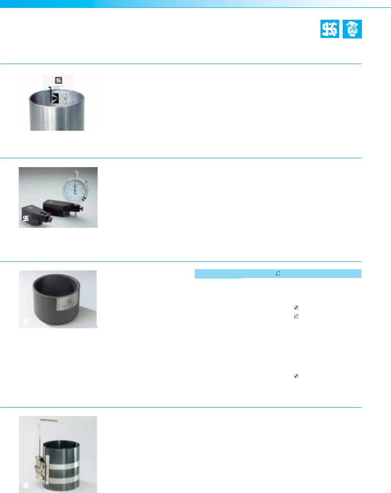
4.2.8 Piston ring scuff band with tightener |
|
|
|
|
|
Infinitely variable |
|
|
|
|
|
adjustment. |
|
|
|
|
|
Part-No. 50 009 816 |
Part-No. 50 009 828 |
|
|
|
|
(Set for passenger cars): |
(Set for trucks): |
|
|
|
|
||
|
|
|
|
Tightening range |
Tightening range |
|
|
|
|
||
Part-No. (car) |
50 009 816 |
57–125 mm |
90–175 mm |
||
Part-No. (truck) |
50 009 828 |
|
|
||
98 | Piston damages – Recognising and rectifying |
MSI Motor Service International |
Piston damages
Recommended tools & testing instruments
Part-No. |
50 009 817 |
4.2.9 Liner flange seat facing attachment
Precision-type facing tool for machining liner flange seats in cylinder blocks.
May even be used with the engine installed. Refacing by hand. The device is locked by an electric
magnet (230 V, 50 Hz connection required).
The delivery scope includes a facing tool, a sturdy wooden case and detailed operating instructions (turning tool not included).
For further technical information refer to Service Information SI 02/2002 ”Liner flange fracture”.
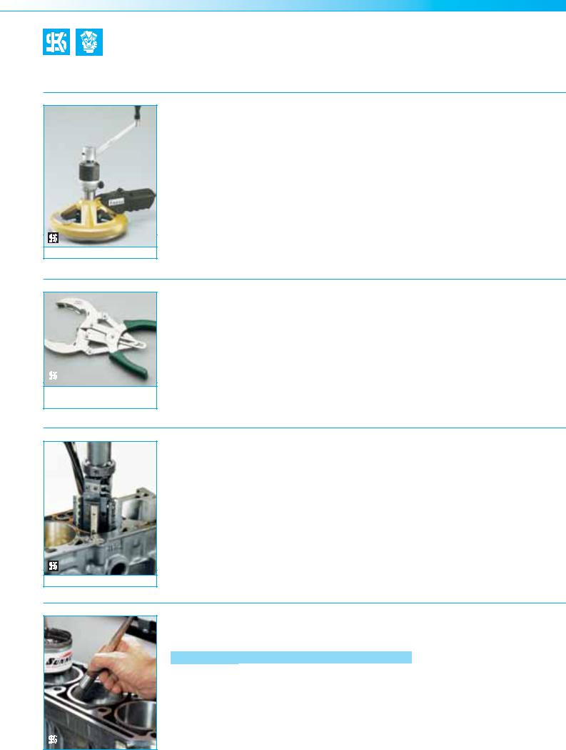
4.2.10 Piston ring pliers
|
For installation and remo- |
Part-No. 50 009 815 |
Part-No. 50 009 829 |
|
val of piston rings. Sturdy |
For piston rings in cars |
For piston rings in trucks |
|
workshop quality. Bright |
50–125 mm |
60–160 mm |
|
nickel-plated. |
|
|
|
|
|
|
|
|
|
|
Part-No. (car)50 009 815 |
|
|
|
|
Part-No. (truck) |
50 009 829 |
|
|
|
|
|
4.2.11 Honing brushes for plateau honing |
|
|
|
|
Honing accessories for cast |
fibres with silicon crystals. |
For further information on |
|
|
iron cylinder blocks for |
A minimum of 10 strokes |
honing cast iron cylinder |
|
|
plateau honing to reduce |
should be carried out using |
blocks, refer to the KS |
|
|
oil consumption and to |
honing oil. In doing so, the |
brochure ”Honing of gray |
|
|
facilitate the running in of |
bore is cleaned and the |
cast iron cylinder blocks” |
|
|
pistons, piston rings and |
peaks are removed. |
(refer to the Appendix for |
|
|
cylinders. |
|
the order number). |
|
|
The set of accessories con- |
Brushing does not cause |
|
Part-No. |
50 009 864 |
tains two honing brushes |
any further dimensional |
|
which consist of nylon |
changes. |
|
||
|
|
|
||
4.2.12 Honing accessories for aluminium cylinder blocks (Alusil®/Silumal®)
|
|
Part-No. |
Description |
|
|
|
|
50 009 860 |
Honing stone set (2 roughing stones) |
||
|
|
|
|
50 009 861 |
Honing stone set (2 roughing stones) |
||
|
|
|
|
50 009 862 |
Honing stone set (2 polishing stones) |
||
|
|
|
|
50 009 863 |
Felt pad set (2 felt pads) |
||
|
|
|
|
50 009 859 |
Silicon paste |
||
|
|
|
|
For further information on honing aluminium engines, refer to the KS brochure ”Reconditioning of aluminium engines” (refer to the Appendix for the order number).
MSI Motor Service International |
Piston damages – Recognising and rectifying | 99 |

Piston damages
Technical brochures
Product Manual – Engine components
Basic technical information on all KS product groups
Part-No. |
Language |
|
Part-No. |
Language |
50 003 734 |
German |
50 003 731 |
Spanish |
|
|
|
|
|
|
50 003 733 |
English |
50 003 580 |
Russian |
|
|
|
|
|
|
50 003 732 |
French |
|
|
|
|
|
|
|
|
Piston damages
Recognising and rectifying
Part-No. |
Language |
50 003 973-01 |
German |
|
|
50 003 973-02 |
English |
|
|
50 003 973-03 |
French |
|
|
Part-No. |
Language |
50 003 973-04 |
Spanish |
|
|
50 003 973-09 |
Russian |
|
|
Additional languages upon request.
Honing of Gray Cast Iron Cylinder Blocks
|
Part-No. |
Language |
|
Part-No. |
Language |
|
50 003 823 |
German |
50 003 818 |
Arabic |
|
|
|
|
|
|
|
|
50 003 822 |
English |
50 003 817 |
Portuguese |
|
|
|
|
|
|
|
|
50 003 821 |
French |
50 003 816 |
Turkish |
|
|
|
|
|
|
|
|
50 003 820 |
Spanish |
50 003 815 |
Russian |
|
|
|
|
|
|
|
|
50 003 819 |
Italian |
50 003 814 |
Czech |
|
|
|
|
|
|
|
|
|
|
|
|
|
Reconditioning of Aluminium Engines
Brochure
|
Part-No. |
Language |
|
Part-No. |
Language |
50 003 813 |
German |
50 003 808 |
Arabic |
||
|
|
|
|
|
|
50 003 812 |
English |
50 003 807 |
Portuguese |
||
|
|
|
|
|
|
50 003 811 |
French |
50 003 806 |
Turkish |
||
|
|
|
|
|
|
50 003 810 |
Spanish |
50 003 805 |
Russian |
||
|
|
|
|
|
|
50 003 809 |
Italian |
50 003 804 |
Czech |
||
|
|
|
|
|
|
|
|
|
|
|
|
Valve Seat Inserts
Technical information and assembly instructions
Part-No. |
Language |
|
Part-No. |
Language |
50 003 728 |
German |
50 003 725 |
Spanish |
|
|
|
|
|
|
50 003 727 |
English |
50 003 724 |
Italian |
|
|
|
|
|
|
50 003 726 |
French |
50 003 700 |
Russian |
|
|
|
|
|
|
100 | Piston damages – Recognising and rectifying |
MSI Motor Service International |