

Dressel.Gruner.Electrodynamics of Solids.2003
.pdf408 |
|
|
Appendix B Medium of finite thickness |
|
|
|
|
||||
(a) |
|
|
(b) |
|
|
|
(c) |
|
|
|
|
1 |
2 |
3 |
1 |
2 |
3 |
4 |
1 |
2 |
3 |
4 |
5 |
Z0 |
Z2 |
Z0 |
Z0 Z2 Z3 |
Z0 |
Z0 Z2 Z3 Z4 Z0 |
||||||
|
d2 |
|
|
d2 |
d3 |
|
|
d2 |
d3 |
d4 |
|
Fig. B.2. (a) Three-layer system: free standing film with impedance Zˆ 2 and thickness d2 surrounded by vacuum (Z0). (b) Four-layer arrangement: film (Zˆ 2, d2) on a substrate with impedance Zˆ 3 and thickness d3. (c) Substrate (Zˆ 3, d3) covered on both sides by films with impedances Zˆ 2 and Zˆ 4 and thicknesses d2 and d4, respectively.
B.2 Impedance mismatch
A very powerful approach to the problems of multilayer reflectivity utilizes the surface impedance of an interface [Hea65, Ram94]. It is useful to start looking at the situation where there are three different regions. Let us assume that a wave traveling in medium 1 hits the boundary to medium 2 and finally enters medium 3 (Fig. B.2a). The reflectivity of the entire system is not completely determined by the impedance of the first and second material but also by the properties of the third material, because part of the light is reflected at the interface between the second and third layers. This effect is taken into account by considering the effective impedance of the second material to be changed by the third one. For normal incidence the light with frequency ω sees the so-called load impedance Zˆ L2 at the first interface between medium 1 and 2; it is given by
|
|
Z |
Z |
Zˆ 3 cosh{−iqˆ2d2} + Zˆ 2 sinh{−iqˆ2d2} |
, |
(B.4) |
|||||||||||
|
|
ˆ L2 = |
ˆ |
2 Zˆ 2 cosh |
{− |
iq2d2 |
} + |
Zˆ |
3 sinh |
{− |
iq2d2 |
} |
|
|
|||
|
|
|
|
|
|
|
ˆ |
|
|
ˆ |
|
|
|||||
where qˆ2 |
= c |
( ˆ)2 |
is the value of the wavevector in medium 2, |
and d2 is |
|||||||||||||
|
ω |
|
|
|
|
|
|
|
|
|
|
|
|
|
|||
|
|
the second material. The reflectivity at this interface is easily |
|||||||||||||||
the thickness of+ |
|
|
|
|
|
|
|
|
|
|
|
|
|
||||
calculated from Eq. (2.4.29) by substituting for Zˆ 2 by this load impedance: |
|||||||||||||||||
|
|
|
|
|
|
r |
Zˆ 1 − Zˆ L2 |
. |
|
|
|
|
|
(B.5) |
|||
|
|
|
|
|
|
ˆ = |
Zˆ 1 + Zˆ L2 |
|
|
|
|
|
|
|
|||
These formulas are applied repeatedly in order to analyze any series of dielectric slabs, no matter what thickness or surface impedance. For example, if another dielectric layer is added at the back as shown in Fig. B.2b, the load impedance Zˆ L3 seen by region 2 is calculated using an equation similar to Eq. (B.4). Then

B.3 Multilayer reflection and transmission |
409 |
Zˆ L3 is used in place of Zˆ 3 in the calculation of Zˆ L2. Following this procedure the load impedance of any multilayer system is evaluated by starting from the rear and adding layer by layer to the front.
In the limiting case of a thin metal film (with impedance Zˆ 2 and with d2 very small) placed in air (Zˆ 3 = Z0), Eq. (B.4) becomes
Z |
= 1 |
Z |
0 − iqˆ2 Zˆ 2d2 |
. |
(B.6) |
||
|
|||||||
ˆ L2 |
− |
Z0 |
(iq2/Zˆ |
2)d2 |
|
|
|
|
|
|
ˆ |
|
|
|
|
The second term in the numerator is negligible for small d2 because the complex dielectric constant ( ˆ)2 of the film cancels. In the denominator, however, the term proportional to d2 must not be neglected as the factor qˆ2/Zˆ 2 is proportional to ( ˆ)2. In the limit where d2 is small, we then arrive at
Zˆ L2 |
= |
|
Z0 |
|
≈ |
|
Z0 |
|
|
(B.7) |
|
|
|
iω |
|
1 |
(σ ) |
|
|||||
|
|
1 |
− Z0( |
4π |
( ˆ)2)d2 |
|
+ Z0 |
ˆ |
2d2 |
||
for the equation of the load impedance of a thin film.
For a two-layer system consisting of a conducting film on a dielectric substrate, Z0 is replaced by the effective impedance of the substrate Zˆ L3:
Zˆ L2 |
= |
|
|
Zˆ L3 |
, |
|
1 |
+ |
Zˆ L3 |
(σ )2d2 |
|||
|
|
|
|
ˆ |
|
|
where the load impedance seen is
Z |
= |
Z |
Z0 cosh{−iqˆ3d3 |
} + |
Zˆ 3 sinh{−iqˆ3d3 |
} |
, |
(B.8) |
||
ˆ L3 |
ˆ D Zˆ 3 cosh |
iq3d3 |
} + |
Z0 sinh |
iq3d3 |
} |
|
|
||
|
|
|
|
{− ˆ |
|
{− ˆ |
|
|
||
where Zˆ 3 is the substrate impedance and d3 is its thickness. In the case where the backing region is another dielectric layer, as shown in Fig. B.2c, the value of Z0 in Eq. (B.8) is replaced by an effective surface impedance which is calculated using the same equations. This procedure can be repeated for any series of layers with different optical properties (n and k) and film thickness d.
B.3 Multilayer reflection and transmission
In the following we discuss the overall reflectivity and transmission of various multilayer systems, starting from one thin layer, going to double layer compounds, etc.
B.3.1 Dielectric slab
The evaluation of the amplitude and phase of the electromagnetic wave is complicated but straightforward (for example by using matrices), and here we merely give

410 |
Appendix B Medium of finite thickness |
the end result, valid for an isotropic and homogeneous medium [Bor99, Hea65]. By calculating the multiple reflections and transmissions at the two symmetrical boundaries (given by z = 0 and z = d), the final expression for the reflectivity RF of a material with finite thickness d is
R |
F = |
R |
(1 − exp{−αd})2 + 4 exp{−αd} sin2 β |
, |
(B.9) |
||||||||||||
(1 − R exp{−αd})2 + 4R exp{−αd} sin2{β + φr} |
|||||||||||||||||
|
|
|
|
||||||||||||||
with the bulk reflectivity |
|
|
|
|
|
|
|
|
|
|
|
|
|
||||
|
|
|
|
|
1 |
|
Nˆ |
|
2 |
(1 |
n)2 |
k2 |
|
|
|||
|
|
|
R = |
|
− |
|
= |
|
− |
+ |
|
|
(B.10a) |
||||
|
|
|
1 |
N |
|
(1 |
n)2 |
k2 |
|
||||||||
|
|
|
|
|
|
+ |
ˆ |
|
|
|
|
+ |
+ |
|
|
|
|
|
|
|
|
|
|
|
|
|
|
|
|
|
|
|
|
||
|
|
|
|
|
|
|
|
|
|
|
|
|
|
|
|
|
|
|
|
|
|
|
|
|
|
|
|
|
|
|
|
|
|
|
|
as in Eq. (2.4.15), obtained in the limiting case for d → ∞; the phase change upon reflection is
|
r = |
|
1 − n2 − k2 |
|
φ |
|
arctan |
−2k |
(B.10b) |
|
|
from Eq. (2.4.14). The power absorption coefficient α = 4π k/λ0 was defined in Eq. (2.3.18); it describes the attenuation of the wave. The angle
β = |
2π nd |
(B.11) |
λ0 |
indicates the phase change on once passing through the medium of thickness d and refractive index n. Here λ0 is the wavelength in a vacuum, and hence β describes the ratio of film thickness and wavelength in the medium. Sometimes it is convenient to combine both in a complex angle δ = β + iαd/2. We obtain for the transmission
T |
|
= |
|
|
[(1 − R)2 + 4R sin2 φr] exp{−αd} |
|
, (B.12a) |
||||||||||||||||||
|
|
(1 − R exp{−αd})2 + 4R exp{−αd} sin2{β + φr} |
|||||||||||||||||||||||
F |
|
|
|||||||||||||||||||||||
φ |
|
|
|
2π nd |
|
arctan |
|
k(n2 + k2 − 1) |
|
|
|
|
|
|
|||||||||||
|
= |
|
λ0 − |
(k2 + n2)(2 + n)n |
|
|
|
|
|
||||||||||||||||
|
t |
|
|
|
|
|
|
|
|
|
|
||||||||||||||
|
|
|
|
|
|
|
|
R exp −αd |
% |
sin2 |
β + φr |
% |
|
. |
|
|
|||||||||
|
|
|
+ arctan |
|
|
|
$ |
|
|
|
|
|
$ |
|
|
|
|
(B.12b) |
|||||||
|
|
|
1 |
− |
R exp |
$− |
αd |
% |
cos2 |
β |
+ |
φr |
|
|
|||||||||||
|
|
|
|
|
|
|
|
|
|
|
|
|
|
|
|
$ |
|
% |
|
|
|||||
The second term in the denominator of Eq. (B.12a) describes the interference; for strong absorption it might be neglected, and the equation then reduces to
TF = |
(1 − R)2(1 + nk22 ) exp{−αd} |
. |
(B.13) |
1 − R2 exp{−2αd} |
This relation also describes the case where the wavelength λ is larger than the film thickness d, and for that reason no interference is present. In the limit of infinite

B.3 Multilayer reflection and transmission |
411 |
thickness (d → ∞), obviously there is no transmission through the material and TF = 0; the radiation is either reflected or fully absorbed. For optically very thin plates (nd λ), both components of the complex angle αd and β are very small, and therefore the reflection RF is also close to zero. The transmission through the material is then given by
|
4 |
π kd |
|
2 |
ω |
|
TF ≈ (1− R)2 exp − |
|
= (1− R)2 exp − |
kd |
= (1− R)2 exp{−αd} ; |
||
|
λ0 |
|
c |
|||
|
|
|
|
|
|
(B.14) |
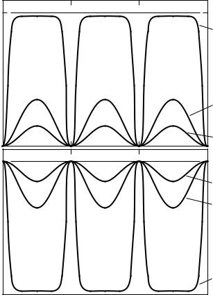
the rest of the signal is absorbed. At intermediate optical thickness one obtains a series of maxima and minima in the transmitted power as the frequency is varied (Fig. B.3). The interference extrema are separated by
f = |
c |
, |
(B.15) |
2nd |
and similar oscillations occur when the thickness is varied keeping the frequency fixed: d = . This phenomenon is utilized to determine the dielectric properties of thin films or transparent media.
It is interesting to consider a very thin metallic film in air as we have done with the impedance approach; in this case Eqs (B.9) and (B.12a) simplify to
|
|
|
|
|
( 12 + 22)4π 2d2/λ02 |
|
|
|
σdc Z0d |
|
2 |
||
RF |
|
|
|
|
|
|
|
||||||
≈ |
4 + 8 2π d/λ0 + ( 12 + 22)4π 2d2/λ02 ≈ |
σdc Z0d + 2 |
|
||||||||||
|
|
||||||||||||
|
= |
1 |
+ |
c |
|
−2 |
|
|
|
|
|
(B.16) |
|
|
|
|
|
|
|
|
|
||||||
|
2π σdcd |
|
|
|
|
|
|
||||||
|
|
|
|
|
|
|
4 |
|
|
2 |
|
2 |
|
TF |
≈ |
|
|
|
|
|
≈ |
, |
|||||
4 + 8 2π d/λ0 + ( 12 + 22)4π 2d2/λ02 |
σdc Z0d + 2 |
||||||||||||
|
|
|
|
σ |
|
−2 |
|
|
|
|
|
||
|
|
|
|
|
|
|
|
|
|
|
|
||
|
= |
1 |
+ |
2π dcd |
|
|
|
|
|
|
|
(B.17) |
|
|
c |
|
|
|
|
|
|
||||||
where Z0 = 377 is the wave impedance of a vacuum, and σdc denotes the dc conductivity of the film. The second approximation used in both relations holds if12 22, and the optical properties then are frequency independent, as it becomes obvious after substituting 2π 2d/λ = σdc Z0d. The absorptivity of the film AF = 1 − RF − TF is given by
AF ≈ |
8 2π d/λ0 |
|
|
|
|
|
||
4 + 8 2π/λ0 + ( 12 + 22)4π 2d2/λ02 |
|
−2 |
||||||
|
4σdc Z0d |
|
c |
1 + |
c |
|
||
≈ |
|
= |
|
|
(B.18) |
|||
(σdc Z0d + 2)2 |
π σdcd |
2π σdcd |
||||||
and is displayed in Fig. B.4. Since the reflection and transmission depend on d,

B.3 Multilayer reflection and transmission |
413 |
Fig. B.4. Reflection RF, transmission TF, and absorption AF of thin metal films as a function of thickness d normalized to the Woltersdorff thickness dW which is given by
dW = 2/σdc Z0.
in Eq. (B.9) then simplifies to the Airy function |
|
|
||||||||
R |
F |
= |
4R sin2{β} |
|
= |
2R − 2R cos{2β} |
|
, |
(B.19) |
|
(1 − R)2 + 4R sin2{β} |
1 + R2 − 2R cos{2β} |
|||||||||
|
|
|
||||||||
as plotted in Fig. B.3a. The interference leads to extrema in the reflectivity given by
|
|
Rextrema |
|
|
1 |
|
exp{−αd} |
|
2 |
|
|
|
|||
|
|
= |
R |
|
|
; |
|
(B.20) |
|||||||
|
|
|
|
|
|
||||||||||
|
|
F |
|
1 ±R exp |
{− |
αd |
|
|
|
||||||
|
|
|
|
|
± |
|
|
|
} |
|
|
|
|
||
for α = 4π νk |
= 0 the minima drop to zero and the maxima reach RFmax = |
||||||||||||||
4R/(1 + R)2, and are evenly spaced by a frequency of f |
= c/(2nd). The |
||||||||||||||
transmission TF shows similar fringes (Fig. B.3b): |
|
|
|
|
|
||||||||||
T |
|
(1 − R)2 |
|
|
|
|
|
(1 − R)2 |
|
, |
(B.21) |
||||
|
|
|
|
= 1 + R2 − 2R cos{2β} |
|||||||||||
F = (1 − R)2 + 4R sin2{β} |
|
|
|||||||||||||
414 |
Appendix B Medium of finite thickness |
|
||||
where the extrema are given by |
|
|
|
|
||
|
T extrema |
= |
(1 − R)2 exp{−αd} |
|
, |
(B.22) |
|
(1 ± R exp{−αd})2 |
|||||
|
F |
|
|
|||
which for α = 0 reaches TFmax = 1 and TFmin = (1 − R)2/(1 + R)2. Hence for a perfect match of wavelength and film thickness all the radiation passes through the film, even for finite refractive index n (e.g. Fabry–Perot filter, etalon).
Following the discussion of the bulk properties in Section 5.1.2, the case of a conductor requires us to look at different frequency ranges separately. The frequency dependence of the reflectivity of a typical metal film is displayed in Fig. B.5a, where we assume a dc conductivity σdc = 105 −1 cm−1 and a plasma frequency νp = ωp/(2π c) = 104 cm−1. It is basically 1 for ω < 1/τ , and decreases significantly only when approaching ωp. Only for very thin films does the plasma edge become broader and the low frequency value of the reflectivity decrease. Note that we do not consider surface scattering or other deviations of the thin film material properties from the bulk behavior. If the layer is much thicker than the skin depth given by Eq. (2.3.15b), there is no interference and the intensity dies off following Beer’s law (2.3.14). This implies that the amplitude of the electric field E decreases to exp{−2π } ≈ 1/536 per wavelength propagating into the metal. In the low frequency limit λ > d, Eq. (B.13) applies, which leads to a frequency independent transmission. Fig. B.5b shows that the transmission has a constant value up to a point where the skin depth δ0 becomes comparable to the sample thickness d, above which it decreases exponentially. With the frequency increasing further, we exceed the Hagen–Rubens limit (ω 1/τ ) and the reflection off the surface decreases, causing a dramatic increase in the transmitted radiation (ultraviolet transparency). For very thin films (e.g. d = 0.1 µm in Fig. B.5b), the transmission does not change. The absorptivity AF = 1 − (RF + TF) shows a similar behavior (Fig. B.5c). For δ0 d the absorptivity is frequency independent; its value is inversely proportional to the thickness of the film. In the range ω 1/τ it follows approximately the Hagen–Rubens relation (5.1.17)
AF ≈ 1 − RF = |
π2σdc |
1/2 |
(B.23) |
||
, |
|||||
|
|
ω |
|
|
|
since TF is many orders of magnitude smaller. Above the scattering rate the absorptivity stays constant up to the plasma frequency.
Finally the optical properties of a thin semiconducting film show distinct differences from those of the bulk material. While the reflectivity RF of an infinitely thick semiconductor slab drops off according to the Hagen–Rubens relation (B.23), the film with a finite thickness has clear modulations due to the multireflections on

416 Appendix B Medium of finite thickness
top of this behavior (Eq. (B.9)). The median reflectivity is given by
Rmedian |
= |
R |
1 + exp{−2αd} |
, |
F |
|
1 + R2 exp{−2αd} |
|
while the values of the minima and maxima can be calculated by Eq. (B.20). Comparison with the insulating case shows that the spacing f = c/(2nd) does not change with increasing losses in the material. The transmission TF and the absorptivity AF = 1 − RF − TF show an interference pattern. The extrema of the transmission are given above by Eq. (B.22); the average transmission can be written as
T median |
= |
(1 − R)2 exp{−αd} |
, |
|
F |
1 + R2 exp{−2αd} |
|
|
|
which in our example is only slightly frequency dependent.
B.3.2 Multilayers
The analysis of the optical properties of a sandwich structure consisting of many layers has to start from the complex Fresnel formulas as derived in Section 2.4
r |
|
= |
Nˆ 1 − Nˆ 2 |
and t |
= |
2Nˆ 2 |
|
(B.24) |
|
Nˆ 1 + Nˆ 2 |
Nˆ 1 + Nˆ |
2 |
|||||
ˆ |
ˆ12 |
|
||||||
|
12 |
|
|
|
|
|
|
|
for light traveling from medium 1 to medium 2. For a one-layer system (i.e. a material of thickness d, refractive index n, and extinction coefficient k which is situated between materials labeled by the subscripts 1 and 3), the total reflection and transmission coefficients are
|
|
|
|
r12 |
r23 exp |
{ |
2iδ |
} |
|
|
|
|
|
tˆ12tˆ23 exp |
{ |
iδ |
} |
|
r |
|
= |
|
ˆ |
+ ˆ |
|
|
and |
t |
= |
|
|
|
, (B.25) |
||||
|
1 + rˆ12rˆ23 exp{2iδ} |
1 + rˆ12rˆ23 exp{2iδ} |
||||||||||||||||
ˆ |
|
ˆ123 |
|
|||||||||||||||
|
123 |
|
|
|
|
|
|
|
|
|
|
|
|
|
|
|
|
|
where the reflection and transmission coefficients of each interface are calculated according to Eqs (B.24) and the complex angle
δ = β + iαd/2 = 2π d(n + ik)/λ0
as defined above. On calculating the power reflection coefficient, we see that these results are identical to the Eqs (B.9) and (B.12a) obtained in the previous subsection.
Obviously this procedure can be repeated for multilayer systems by applying the same method developed in the impedance mismatch approach (Section B.2). The complex reflection coefficient rˆ23 of the last interface has to be replaced by the total

B.3 Multilayer reflection and transmission |
417 |
reflection coefficient of two subsequent interfaces according to Eq. (B.25). Thus we obtain after some rearrangement
|
|
rˆ12 + rˆ23 exp{2iδ2} + rˆ34 exp |
|
2i(δ2 + δ3) |
+ rˆ12rˆ23rˆ34 exp |
|
2iδ3 |
|
||||||||||||||||
rˆ1234 |
= |
1 r12r23 exp 2i |
δ |
2 |
r |
23r34 |
$ |
|
|
2iδ |
3 |
% 12 |
r |
34 |
exp |
|
2i(δ |
2 |
$ |
|
δ |
3% |
. |
|
+ ˆ ˆ |
$ |
% |
|
exp |
$ |
|
r |
|
$ |
|
+ |
) |
||||||||||||
|
|
|
+ ˆ ˆ |
|
|
|
% + ˆ |
ˆ |
|
|
|
|
% |
|
||||||||||
(B.26) The corresponding formula describing the transmission of layer 2 and layer 3 between media 1 and media 4 has the form
|
|
|
|
12 |
|
23 |
|
|
|
2 |
tˆ12tˆ23tˆ34 exp |
$ |
i(δ2 + δ3) |
|
|
|
|
|
|
|
||||||||
tˆ1234 = |
|
|
|
|
|
|
|
|
23 |
|
34 |
|
|
|
3 |
% |
|
|
|
|
|
|
, |
|||||
1 |
r |
|
r |
|
exp |
$ |
2iδ |
% |
r |
|
r |
|
exp |
$ |
2iδ |
|
r12r34 exp |
$ |
2i(δ2 |
+ |
δ3) |
|
||||||
where tˆpq |
|
|
+ ˆ |
ˆ |
|
|
+ ˆ |
ˆ |
|
|
|
|
% + ˆ |
ˆ |
|
|
%(B.27) |
|||||||||||
and rpq are the complex Fresnel transmission and reflection coefficients |
||||||||||||||||||||||||||||
|
|
|
ˆ |
|
|
|
|
|
|
|
|
|
|
|
|
|
|
|
|
|
|
|
|
|
|
|
|
|
at the boundaries between media p and media q (with p, q = 1, 2, 3, 4), and the complex angle δp = βp + iαpdp/2 = 2π dp(n p + ikp)/λ0.
By iteration we arrive at the equations for a three-layer system: |
|
||
rˆ12345 = |
A |
, |
(B.28) |
|
|||
B |
|||
where
A= rˆ12 + rˆ23 exp{2iδ2} + rˆ34 exp{2i(δ2 + δ3)} + rˆ45 exp$2i(δ2 + δ3 + δ4)%
+rˆ12rˆ23rˆ34 exp{2iδ3} + rˆ23rˆ34rˆ45 exp{2i(δ2 + δ4)}
+rˆ12rˆ34rˆ45 exp{2iδ4} + rˆ12rˆ23rˆ45 exp{2i(δ3 + δ4)}
and
B= 1 + rˆ12rˆ23 exp$2iδ2% + rˆ23rˆ34 exp$2iδ3% + rˆ34rˆ45 exp$2iδ4%
+rˆ12rˆ34 exp$2i(δ2 + δ3)% + rˆ23rˆ45 exp$2i(δ3 + δ4)%
+ rˆ12rˆ45 exp$2i(δ2 + δ3 + δ4)% + rˆ12rˆ23rˆ34rˆ45 exp$2i(δ2 + δ4)% .
The transmission coefficient of the three-layer system is given by (layers 2, 3, and 4 between media 1 and 5)
tˆ12345 = |
ˆ12tˆ23tˆ34tˆ45 exp$B |
2 + |
δ |
3 + |
δ |
4 |
% |
, |
(B.29) |
|
|
t |
i(δ |
|
|
|
) |
|
|
||
where the notations are the same as used before.
In practice a transparent known substrate covered on one side with the material of interest represents a typical two-layer system. The values n and k of the bare substrate are known or measured beforehand. In Fig. B.6 the influence of the thickness of a conducting film on the interference pattern is demonstrated. One side of a sapphire substrate (d3 = 0.41 mm) is covered with a metallic film of NbN with d2 = 20 A,˚ 140 A,˚ and 300 A˚ (curves 2, 3, and 4, respectively). The