

16 |
2.3 Preemptive Multitasking |
|
|
CLK
OUT1
OUT0
CLOCK |
TASK SWITCH |
.TEXT1
.TEXT0
ROM
CPU0 |
|
|
CPU1 |
||
|
|
|
|
|
|
|
|
|
|
|
|
|
|
|
|
|
|
|
|
|
|
|
|
.DATA1
.DATA0
RAM
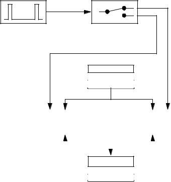
FIGURE 2.8 Shared ROM and RAM
By using the shared RAM, the two CPUs can communicate with each other. We have thus lost one of the advantages listed in Table 2.2: the CPUs are no longer protected against each other. So if one CPU overwrites the DATA segment of the other CPU during a crash, then the second CPU will most likely crash, too. However, the risk of one CPU going into an endless loop is yet eliminated. By the way, when using cooperative multitasking, an endless loop in one task would suspend all other tasks from operation.
2.3.3 Task Control Blocks
The final steps to complete our model are to move the duplicated CPU, and to implement the task switch in software rather than in hardware. These two steps are closely related. The previous step of two CPUs sharing one ROM and one RAM was relatively easy to implement by using different sections of the ROM and RAM. Replacing the two CPUs by a single one is not as easy, since a CPU
2. Concepts |
17 |
|
|
cannot be divided into different sections. But before discussing the details, let us have a look at the final configuration which is shown in Figure 2.9:
.TEXT1
.TEXT0
ROM
INT
CPU
CLOCK
.DATA1
.DATA0
RAM
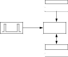
FIGURE 2.9 Final Hardware Model for Preemptive Multitasking
In contrast to the configuration with two CPUs shown in Figure 2.8, the final configuration (see Figure 2.9) has only one CPU and no task switch. Moreover, the CLK signal has been replaced by an INT signal. This signal indicates that in the final model, task switching is initiated by a regular interrupt towards the CPU.
The final configuration is very similar to our initial model shown in Figure 2.4 on page 13. We merely have added the clock device, which is now connected to the interrupt input of the CPU. Note that our final model is able to run more than two programs in parallel.
The main reason why we wanted to remove the duplicated CPU is the following: Think of the two CPUs shown in Figure 2.8 on page 16. At any time, these two CPUs are most likely in different states. The two possible states are represented by the internal registers of the CPU and determined by the programs executed by the CPUs. So to remove the duplicated CPU, we need to replace the hardware task switch by a software algorithm. Upon a task switch event (that is, the time when the clock signal goes inactive, or low), the state of one CPU needs to be saved, and the state of the second CPU needs to be restored. So we obtain the following algorithm:
•Save the internal registers of CPU0
•Restore the internal registers of CPU1
18 |
2.3 Preemptive Multitasking |
|
|
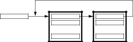
However, this algorithm does not make much sense, as our final model in Figure 2.9 on page 17 is to have only one CPU. Instead of having two CPUs, we use a data structure called TCB, Task Control Block, to represent the CPUs of the system. These TCBs provide space for storing the contents of the CPUs’ registers R0 to Rn. Moreover, each TCB has a pointer to the TCB that represents the next CPU. The task switch of Figure 2.8 on page 16 is replaced by a variable, CurrentTask. The TCB concept is illustrated in Figure 2.10.
CurrentTask |
NextTask |
NextTask |
|
R0 |
R0 |
|
... |
... |
|
Rn |
Rn |
FIGURE 2.10 Task Control Blocks and CurrentTask
As a result, the proper task switch algorithm, which is an Interrupt Service Routine, ISR, is as follows:
•Reset the interrupt, if required
•Store the internal CPU registers into the TCB to which CurrentTask is pointing
•Replace CurrentTask by NextTask pointer of the TCB to which CurrentTask is pointing
•Restore the internal CPU registers from the TCB to which CurrentTask points now
•Return from ISR
Not that the ISR itself does not change the CPU state during the task switch. But this ISR is all we need for preemptive multitasking. By inserting further TCBs in the TCB NextTask pointer ring, the model can be extended to perform any number of tasks.
There is an important invariant for this scheme: Whenever a task examines the variable CurrentTask, it will find this variable pointing to its own TCB . If
CurrentTask does not point to some arbitrary task, then this task is not active at
2. Concepts |
19 |
|
|
that time, and thus this condition cannot be detected. In brief, for every task, CurrentTask refers to the tasks’s own TCB.
2.3.4 De-Scheduling
Up to now, our two tasks had equal share of CPU time. As long as both tasks are busy with useful operations, there is no need to change the distribution of CPU time. For embedded systems, however, a typical situation is as follows: each task waits for a certain event. If the event occurs, the task handles this event. Then the task waits for the next event, and so on. For example, assume that each of our tasks monitors one button which is assigned to the relevant task. If one of the buttons is pressed, a long and involved computation, lic, is called:
task_0_main()
{
for (;;)
if (button_0_pressed()) lic_0();
}
task_1_main()
{
for (;;)
if (button_1_pressed()) lic_1();
}
As task switching is controlled by our clock device, each task consumes 50 percent of the CPU time, regardless of whether a button is being pressed or not. This situation is described as busy wait. So precious CPU time is wasted by the tasks being busy with waiting as long as the button_x_pressed() functions return 0. To ensure optimal exploitation of CPU time, we add a DeSchedule() function which causes a task to release explicitly its CPU time:
task_0_main() |
|
|
{ |
|
|
for |
(;;) |
|
|
if (button_0_pressed()) lic_0(); |
|
|
else |
DeSchedule(); |
} |
|
|
task_1_main() |
|
|
{ |
|
|
for |
(;;) |
|
|
if (button_1_pressed()) lic_1(); |
|
|
else |
DeSchedule(); |
} |
|
|
So the DeSchedule() function initiates the same activities as our ISR, except that there is no interrupt to be reset. Unless both buttons are pressed simultaneously,
20 |
2.3 Preemptive Multitasking |
|
|
the DeSchedule() function allows to assign the CPU time to the task that actually needs it, while still maintaining the simplicity of our model. Note that explicit descheduling should only be used rarely, because … (ausdrückliche Begründung fehlt!!!).