

4 Bootstrap
4.1Introduction
In this chapter, the start-up of the kernel is described. It contains two phases: the initialization of the system after RESET, and the initialization of the tasks defined in the application.
4.2System Start-up
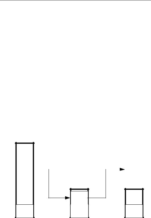
The compilation of the various source files and the linking of the resulting object files results in two files containing the .TEXT and ..DATA sections of the final system (see also Section 2.1.1). The linker has generated addresses referring to the .DATA section, which normally starts at the bottom of the system’s RAM. After RESET, however, this RAM is not initialized. Thus the .DATA section must be contained in the system’s ROM and copied to the RAM during system start-up,
??? as shown in Figure 4.1 ???
|
|
|
|
|
|
.DATA |
|
|
|
|
.DATA |
|
|
||||
|
|
|
|
|
|
|
|
|
|
|
RAM |
.DATA
.TEXT  .TEXT
.TEXT  .TEXT
.TEXT
ROM |
ROM |
FIGURE 4.1 ??? .DATA and .TEXT during System Start-Up ???
82 |
4.2 System Start-up |
|
|
The .TEXT section, in contrast, does not need any special handling. Figure 4.1 shows the output of the linker on the left. The ROM image for the system is created by appending the .DATA section after the .TEXT section. The address of the .DATA section in ROM can be computed from the end of the .TEXT section; this address is provided by the linker (symbol _etext). Depending on the target system for which the linker has been installed, _etext may need to be rounded up (e.g. to the next 2Kbyte boundary) to determine the exact address of the .DATA section in RAM. Although it is not strictly necessary, it is generally a good idea to initialize the unused part of the RAM to 0. This allows to reproduce faults created by uninitialized variables.
After RESET, the CPU loads its supervisor stack pointer with the vector at address 0 and its program counter with the next vector. In our implementation, the vector for the supervisor stack pointer is somewhat abused, as it contains a branch to the start of the system initialization. This allows for issuing a JMP 0 (in supervisor mode) to restart the system, although this feature is not used yet. These two vectors are followed by the other exception vectors. Most of them are set to label _fatal, which is the handler for all fatal system errors.
1 |
| crt0.S |
|
37 |
_null: BRA |
_reset |
38 |
.LONG |
_reset |
39 |
.LONG |
_fatal, _fatal |
40 |
.LONG |
_fatal, _fatal |
41 |
.LONG |
_fatal, _fatal |
42 |
.LONG |
_fatal, _fatal |
43 |
.LONG |
_fatal, _fatal |
44 |
|
|
45 |
.LONG |
_fatal,_fatal,_fatal |
46 |
.LONG |
_fatal,_fatal,_fatal |
47 |
.LONG |
_fatal,_fatal,_fatal |
48 |
.LONG |
_fatal,_fatal,_fatal |
49 |
|
|
50 |
.LONG |
_fatal |
51 |
.LONG |
_fatal |
52 |
.LONG |
_duart_isr |
53 |
.LONG |
_fatal |
54 |
.LONG |
_fatal, _fatal |
55 |
.LONG |
_fatal, _fatal |
56 |
|
|
57 |
.LONG |
_stop |
58 |
.LONG |
_deschedule |
59 |
.LONG |
_fatal |
60 |
.LONG |
_Semaphore_P |
61 |
.LONG |
_Semaphore_V |
62 |
.LONG |
_Semaphore_Poll |
63 |
.LONG |
_fatal, _fatal |
64 |
.LONG |
_fatal, _fatal |
65 |
.LONG |
_fatal, _fatal |
66 |
.LONG |
_fatal |
67 |
.LONG |
_set_interrupt_mask |
68 |
.LONG |
_readByteRegister_HL |
69 |
.LONG |
_writeByteRegister |
... |
|
|
| |
0 |
initial SSP (end of RAM) |
|
| |
1 |
initial PC |
|
| |
2, 3 |
bus error, adress error |
|
| |
4, 5 illegal instruction, divide/0 |
||
| |
6, 7 |
CHK, |
TRAPV instructions |
| |
8, 9 |
privilege violation, trace |
|
| 10,11 |
Line |
A,F Emulators |
|
| |
|
|
|
| 12... |
(reserved) |
||
| 15... |
(reserved) |
||
| 18... |
(reserved) |
||
| 21... |
(reserved) |
||
| |
|
|
|
| 24 |
spurious interrupt |
||
| 25 |
level 1 autovector |
||
| 26 |
level 2 autovector |
||
| 27 |
level 3 autovector |
||
| 28,29 |
level 4,5 autovector |
||
| 30,31 level |
6,7 autovector |
||
| |
|
|
|
| 32 |
TRAP |
#0 vector |
|
| 33 |
TRAP |
#1 vector |
|
| 34 |
TRAP |
#2 vector |
|
| 35 |
TRAP |
#3 vector |
|
| 36 |
TRAP |
#4 vector |
|
| 37 |
TRAP |
#5 vector |
|
| 38,39 |
TRAP |
#6, #7 vector |
|
| 40,41 |
TRAP |
#8, #9 vector |
|
| 42,43 |
TRAP |
#10,#11 vector |
|
| 44 |
TRAP |
#12 vector |
|
| 45 |
TRAP |
#13 vector |
|
| 46 |
TRAP |
#14 vector |
|
| 47 |
TRAP |
#15 vector |
|
4. Bootstrap |
83 |
|
|
Thus after RESET, processing continues at label _reset. The supervisor stack pointer is initialized to point to the top of the RAM. This is necessary because the vector for this purpose was abused for the branch to _reset. Next the vector base register (VBR) is set to the beginning of the vector table. This applies only for MC68020 chips and above and allows for relocation of the vector table. Actually, the branch to _reset is intended for jumping to the content of the VBR so that the system can be restarted with a relocated .TEXT section, provided that the VBR points to the proper vector table. For processors such as the MC68000 that do not provide a VBR, this instruction must be removed. After setting the VBR, the LEDs are turned off.
81 |
_reset: |
|
| |
82 |
MOVE.L |
#RAMend, SP |
| since we abuse vector 0 for BRA.W |
83 |
LEA |
_null, A0 |
| |
84 |
MOVEC |
A0, VBR |
| MC68020++ only |
85 |
|
|
| enable cache |
86 |
MOVE.B |
#0, wDUART_OPCR |
| all outputs via BSET/BCLR |
87 |
MOVE.B |
#LED_ALL, wLED_OFF |
| all LEDs off |
Then the RAM is initialized to 0. The end of the .TEXT section is rounded up to the next 2Kbyte boundary (assuming the linker was configured to round up the
.TEXT section to a 2Kbyte boundary), which yields the start of the .DATA section in ROM. The size of the .DATA section is computed, and the .DATA section is then copied from ROM to the RAM.
89 |
MOVE.L |
#RAMbase, A1 |
| clear RAM... |
90 |
MOVE.L |
#RAMend, A2 |
| |
91 |
L_CLR: CLR.L |
(A1)+ |
| |
92 |
CMP.L |
A1, A2 |
| |
93 |
BHI |
L_CLR |
| |
94 |
|
|
| relocate data section... |
95 |
MOVE.L |
#_etext, D0 |
| end of text section |
96 |
ADD.L |
#0x00001FFF, D0 |
| align to next 2K boundary |
97 |
AND.L |
#0xFFFFE000, D0 |
| |
98 |
MOVE.L |
D0, A0 |
| source (.data section in ROM) |
99 |
MOVE.L |
#_sdata, A1 |
| destination (.data section in RAM) |
100 |
MOVE.L |
#_edata, A2 |
| end of .data section in RAM |
101 |
L_COPY: MOVE.L |
(A0)+, (A1)+ |
| copy data section from ROM to RAM |
102 |
CMP.L |
A1, A2 |
| |
103 |
BHI |
L_COPY |
| |
At this point, the .TEXT and .DATA sections are located at those addresses to which they had been linked. The supervisor stack pointer is set to the final supervisor stack, and the user stack pointer is set to the top of the idle task’s user stack (the code executed here will end up as the idle task).
105 |
MOVE.L |
#_SS_top, A7 |
| set up supervisor stack |
106 |
MOVE.L |
#_IUS_top, A0 |
| |
107 |
MOVE |
A0, USP |
| set up user stack |
Finally (with respect to crt0.S), the CPU enters user mode and calls function _main(). It is not intended to return from this call; if this would happen, then it would be a fatal system error.
84 |
4.2 System Start-up |
|
|
108 |
|
|
| |
109 |
MOVE |
#0x0700, SR |
| user mode, no ints |
110 |
JSR |
_main |
| |
111 |
|
|
| |
112 |
_fatal: |
|
| |
If for any reason label _fatal is reached, then all interrupts are disabled, the red LED is turned on, and the SERIAL_1 transmitter is enabled to allow for polled serial output. Then the present supervisor stack pointer, which points to the exception stack frame created for the fatal system error, is saved and the supervisor stack pointer is set to the end of the RAM. Then os::Panic() is called forever with the saved exception stack frame as its argument. os::Panic() prints the stack frame in a readable format on the SERIAL_1 channel, so that the cause of the fault can easily be determined. It ??? what is it ??? is called forever, so that a terminal can be connected to SERIAL_1 even after a fatal system error and the stack frame is not lost, but repeated forever.
112 |
_fatal: |
|
| |
113 |
MOVE.W |
#0x2700, SR |
| |
114 |
MOVE.B |
#LED_RED, wLED_ON |
| red LED on |
115 |
MOVE.B |
#0x04, wDUART_CR_B |
| enable transmitter |
116 |
MOVE.L |
SP, A0 |
| old stack pointer |
117 |
MOVE.L |
#RAMend, SP |
| |
118 |
_forever: |
|
| |
119 |
MOVE.L |
A0, -(SP) |
| save old stack pointer |
120 |
MOVE.L |
A0, -(SP) |
| push argument |
121 |
JSR |
_Panic__2osPs |
| print stack frame |
122 |
LEA |
2(SP), SP |
| remove argument |
123 |
MOVE.L |
(SP)+, A0 |
| restore old stack pointer |
124 |
BRA |
_forever |
| |
125 |
|
|
| |
126 |
_on_exit: |
|
| |
127 |
RTS |
|
| |
In general, a function name in assembler refers to a C function, whose name is the same except for the leading underscore. This would mean that “JSR _main” would call main(), which is defined in Task.cc. For the GNU C++ compiler/ linker, the main() function is handled in a special way. In this case, a function __main() is automatically created and called just before main(). This __main() function basically calls the constructors for all statically defined objects so that these are initialized properly. The way this is done may change in future, so special attention should be paid to the compiler/linker release used. The __main function also calls on_exit() (i.e. label _on_exit above), which just returns. So the call of main() in crt0.S basically initializes the static objects and proceeds in the real main().
Now the CPU is in user mode, but interrupts are still disabled. First, the variable SchedulerStarted is checked to ensure main() is not called by mistake; in our case SchedulerStarted is 0.
1 // Task.cc
...
4. Bootstrap |
85 |
|
|
78 |
void main() |
79 |
{ |
80 |
if (Task::SchedulerStarted) return -1; |
Then a vector containing all tasks known at system start-up is initialized to 0 and setupApplicationTasks() is called. In setupApplicationTasks(), all tasks required by the application are created (see also Section 4.3). All tasks created have their status set to STARTED. That is, the task ring is completely set up, but no task is in state RUN. Next, the status for each task is set from STARTED to RUN.
82 |
for (int i = 0; i < TASKID_COUNT; i++) Task::TaskIDs[i] = 0; |
83 |
setupApplicationTasks(); |
84 |
|
85for (Task * t = Task::currTask->next; t != Task::currTask; t = t->next)
86t->TaskStatus &= ~Task::STARTED;
Here all tasks are in state RUN, but interrupts are still disabled. In the next step, variable SchedulerStarted is set to prevent subsequent calls to main() (which would have disastrous effects). Then the hardware is initialized to level Interrupt_IO, and finally interrupts are enabled. The idle task then de-schedules itself, which causes the task with the highest priority to execute. The idle task itself goes into an infinite loop. Whenever the idle task is swapped in (i.e. no other task is in state RUN), it calls os::Stop().
88 |
Task::SchedulerStarted = 1; |
89 |
os::init(os::Interrupt_IO); // switch on interrupt system |
90 |
os::set_INT_MASK(os::ALL_INTS); |
91 |
|
92 |
Task::Dsched(); |
93 |
|
94 |
for (;;) os::Stop(); |
95 |
|
96return 0; /* not reached */
97}
Function os::Stop() merely executes TRAP #0.
1 /* os.cc */
...
67void os::Stop()
68{
69asm("TRAP #0");
70}
The CPU thus enters supervisor mode, fetches the corresponding vector and proceeds at label _stop.
1 |
| crt0.S |
|
|
... |
|
|
|
57 |
.LONG _stop |
| 32 |
TRAP #0 vector |
At label _stop, the yellow LED (which is turned on at every interrupt) is turned off. The CPU then stops execution with all interrupts enabled until an interrupt
86 |
4.2 System Start-up |
|
|
occurs. That is, the yellow LED is turned on whenever the CPU is not in stopped mode, thus indicating the CPU load. After an interrupt occurred, the CPU proceeds at label _return_from_exception, where it checks if a task switch is required. Note that the interrupt itself cannot cause a task switch directly, since the interrupt occurs while the CPU is in supervisor mode.
223 |
_stop: |
|
|
| |
224 |
|
MOVE.B |
#LED_YELLOW, wLED_OFF |
| yellow LED off |
225 |
|
STOP |
#0x2000 |
| |
226 |
|
BRA |
_return_from_exception |
| check for task switch |
227 |
|
|
|
| |
After having left supervisor mode, the idle task is again in its endless loop and stops the CPU again, provided that no other task with higher priority is in state RUN.