

12 |
2.3 Preemptive Multitasking |
|
|
2.3Preemptive Multitasking
The previous sections described the execution of one program at a time. But what needs to be done if several programs are to be executed in parallel? The method we have chosen for parallel processing is preemptive multitasking. By definition, a task is a program that is to be executed, and multitasking refers to several tasks being executed in parallel. The term preemptive multitasking as such may imply a complex concept. But it is much simpler than other solutions, as for example TSR (Terminate and Stay Resident) programs in DOS, or cooperative multitasking.
To explain the concepts of preemptive multitasking, we developed a model which is described in the following sections.
2.3.1 Duplication of Hardware
Let us start with a single CPU, with a program memory referred to as ROM (Read Only Memory), and a data memory, RAM (Random Access Memory). The CPU may read from the ROM, as well as read from and write to the RAM. In practice, the ROM is most likely an EEPROM (Electrically Erasable Programmable ROM). The CPU reads and executes instructions from the ROM. These instructions comprise major parts of the TEXT section in our example program on page 7. Some of these instructions cause parts of the RAM to be transferred into the CPU, or parts of the CPU to be transferred to the RAM, as shown in Figure 2.4 on page 13. For general purpose computers, the program memory is a RAM, too. But in contrast to embedded systems, the RAM is not altered after the program has been loaded – except for programs which modify themselves, or paged systems where parts of the program are reloaded at runtime.
2. Concepts |
13 |
|
|
.TEXT
ROM
CPU
.DATA
RAM
FIGURE 2.4 Program Execution
Now let us assume we have two different programs to be run in parallel. This can be achieved surprisingly easy_ by duplicating the hardware. Thus, one program can be executed on one system, and the second program can be executed on the other system, as shown in Figure 2.5. Note that the TEXT and DATA sections are at different locations in the ROMs and RAMs of Figure 2.5.
.TEXT1
.TEXT0
ROM0 |
ROM1 |
CPU0 |
CPU1 |
|
|
|
|
|
.DATA1 |
.DATA0 |
|
|
|
RAM1 |
|
RAM0 |
|
FIGURE 2.5 Parallel execution of two programs
14 |
2.3 Preemptive Multitasking |
|
|
Because of the increased hardware costs, this approach for running different programs in parallel is not optimal. But on the other hand, it has some important advantages which are listed in Table 2.2. Our goal will be to eliminate the disadvantage while keeping the benefits of our first approach.
Advantages |
Disadvantages |
|
|
The two programs are entirely |
Two ROMs are needed (although |
protected against each other. If one |
the total amount of ROM space is |
program crashes the CPU, then the |
the same). |
other program is not affected by the |
|
crash. |
|
|
|
|
Two RAMs are needed (although |
|
the total amount of RAM space is |
|
the same). |
|
|
|
Two CPUs are needed. |
|
|
|
The two programs cannot |
|
communicate with each other. |
|
|
TABLE 2.2 Duplication of Hardware
2.3.2 Task Switch
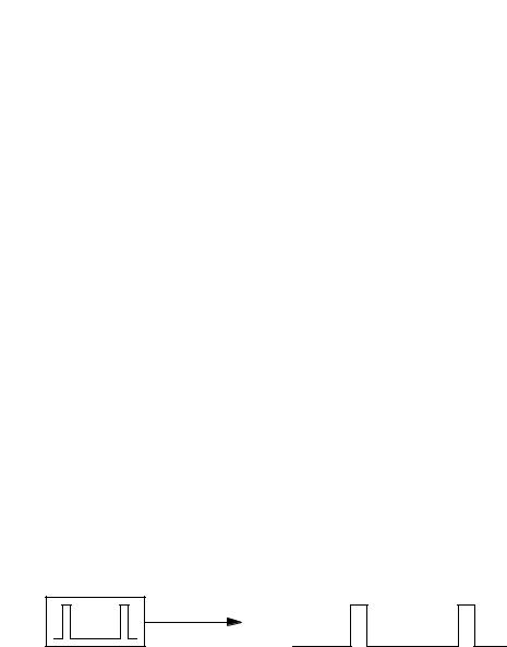
The next step in developing our model is to eliminate one of the two ROMs and one of the two RAMs. To enable our two CPUs to share one ROM and one RAM, we have to add a new hardware device: a clock. The clock has a single output producing a signal (see Figure 2.5). This signal shall be inactive (low) for 1,000 to 10,000 CPU cycles, and active (high) for 2 to 3 CPU cycles. That is, the time while the signal is high shall be sufficient for a CPU to complete a cycle.
CLOCK
FIGURE 2.6 Clock
2. Concepts |
15 |
|
|
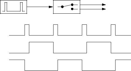
The output of the clock is used to drive yet another device: the task switch (see Figure 2.7). The task switch has one input and two outputs. The outputs shall be used for turning on and off the two CPUs. The clock (CLK) signal turning from inactive to active is referred to as task switch event. On every task switch event, the task switch deactivates the active output, OUT0 or OUT1. Then the task switch waits until the CLK signal becomes inactive again in order to allow the CPU to complete its current cycle. Finally, the task switch activates the other output, OUT0 or OUT1.
CLK |
OUT1 |
|
OUT0 |
CLOCK |
TASK SWITCH |
CLK |
|
OUT0
OUT1
FIGURE 2.7 Task Switch
Each of the CPUs has an input that allows the CPU to be switched on or off. If the input is active, the CPU performs its normal operation. If the input goes inactive, the CPU completes its current cycle and releases the connections towards ROM and RAM. This way, only one CPU at a time is operating and connected to ROM and RAM, while the other CPU is idle and thus not requiring a connection to ROM and RAM. Consequently, we can remove the duplicated ROM and RAM from our model, and the remaining ROM and RAM can be shared by the two CPUs (see Figure 2.8).