

Rivero L.Encyclopedia of database technologies and applications.2006
.pdfthe application domain in a formalism that is technol- ogy-independent, such as the entity-relationship model. The logical schema is the translation of the conceptual schema according to the model of a family of DBMSs. The physical schema adds to the logical structures DBMS-specific technical constructs intended to give the database such properties as efficiency and reliability. The code translates the physical schema into a compilable DDL program.
Once a database has been deployed in its production environment, it enters a maintenance and evolution cycle, through which its schema (and consequently its contents) is continuously modified to follow the evolution of functional, organizational, and technological requirements. Both modern and legacy databases are migrated to more advanced platforms; they are integrated to form federations, generally through wrapping and mediation techniques; and they are interfaced with the Web and feed data warehouses. These processes all require the availability of a precise, up-to-date documentation of the concerned databases. Whenever this documentation is missing, the databases must be redocumented, a process called reverse engineering.
DB CASE tools are to support these processes, ranging from traditional analysis and design to reverse engineering and federation. They collect, store, and manage not only schemas and their interrelationships (ensuring traceability), but also pieces of code and multimedia documentation related to each step of the database life cycle.
A large organization can include several hundreds of databases, each described by several schemas. Each schema appears to be a graph, made up of hundreds of thousands of vertexes (abstracting entity types, attributes, relationship types and roles, constraints, etc.) This size factor implies specific representation modes and powerful tools to consult, analyze, and transform schemas. Large collections of databases require several design and development teams that call for collaborative work support. Finally, no two organizations are alike and share the same methodological culture, so CASE tool customization and extendability are often highly desirable.
In the next section, we will discuss some important functions of DB CASE tools that derive from these requirements.
FUNCTIONS OF CASE TOOLS
Schema Management
This is the basic goal of any CASE tool, namely, allowing developers to enter schemas, including through
CASE Tools for Database Engineering
graphical interfaces; to store them into a schema database, called a repository or encyclopedia; to consult, browse through, and query them; to view them through adequate visualization modes; to output printable documentation; and to exchange specifications with other CASE tools, notably through interchange formats such as XMI (Object Managment Group, 2003).
Schemas are expressed into a specific model, depending on the abstraction level and the concerned technology. At the conceptual level, most tools rely on some sort of entity-relationship model. The UML class diagrams belong to this family and are gaining increasing popularity. However, their weaknesses and idiosynchrasies make them a poor support to express large and complex schemas, specially in nonstandard processes such as reverse engineering.
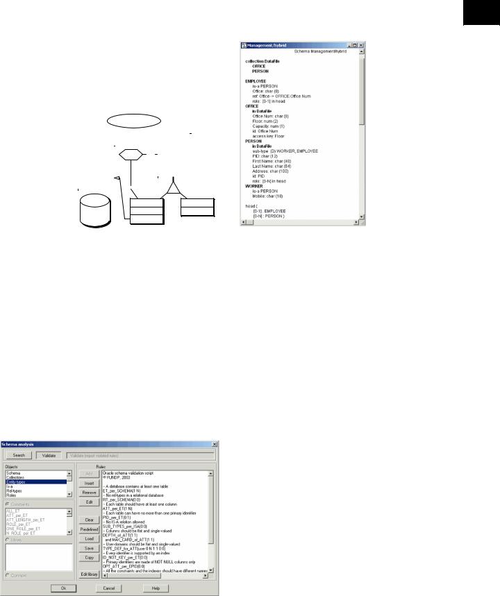
DB-MAIN is based on the wide-spectrum model GER (generic Entity-relationship) that encompasses most commonly used models, whatever their abstraction level and their technology (Hainaut, 1996). An operational model M is defined by a specialization mechanism through which the constructs of the GER pertinent in M are selected and renamed, and the assembly rules for valid M schemas are stated. The GER includes such constructs as entity types, domains, attributes, relationship types, methods, and a large variety of integrity constraints. It also comprises logical and technical constructs, such as foreign keys, access paths, access keys, and files. The tool includes the rules for the most popular models such as Entity-relationship, extended UML class diagrams (DBUML), relational, object-oriented, CODASYL, COBOL files, and XML (DTD and Schemas). Additional personalized models can be defined thanks to a method engineering environment. Figure 1 shows a hybrid schema that includes constructs from several technologies and several abstraction levels. Such a schema is usual in ongoing reverse engineering projects.
DB-MAIN offers several ways to query and browse through a schema. In addition to six customizable views of schemas, two of them being illustrated in Figure 1, objects can be selected by name patterns, keywords in object annotations, and structural patterns. Selected objects can be marked in order to be retrieved later or to be passed as arguments to further processes.
Schema Checking and Validation
Depending on the methodological standard adopted or the target technology, schemas are to meet specific requirements in order to be valid. In particular, a schema can be analyzed against a definite model to check whether it complies with it. For instance, a conceptual schema that has been transformed into XML structures should be validated against the XML schema model before passing it to the code generator.
60
TEAM LinG
CASE Tools for Database Engineering
Figure 1. Graphical and hypertext views of a hybrid DB-MAIN schema. They show examples of entity types, IS-
A hierarchy, attributes, and relationship types and attributes, but also logical constructs such as a foreign key C as well as physical constructs (data file and access key).
|
Management/hybrid |
|
|||||
|
|
|
|
|
|
|
|
|
|
|
|
|
|
|
PERSON |
|
|
|
|
|
|
|
|
|
|
|
|
|
|
|
PID |
OFFICE |
|
head |
|
|
First Name |
||
|
|
0-N |
|
||||
Office Num |
|
|
Last Name |
||||
|
|
|
|
|
|
||
Floor |
|
|
|
|
|
|
Address |
Capacity |
|
|
|
|
|
|
id: PID |
id: Office Num |
|
|
|||||
|
|||||||
acc: Floor |
|
|
|
|
|
|
D |
|
|
0-1 |
|
|
|
||
|
|
|
|
|
|
||
|
|
|
|
|
|
||
|
|
|
|
|
|
|
|
DataFile |
OFFICE |
PERSON |
EMPLOYEE |
WORKER |
Office |
Mobile |
ref: Office |
|
DB-MAIN includes a Schema Analyzer (see Figure 2) that provides three main functions. First, it allows the designer to build, save, and reuse specific models as a set of rules defined by structural predicates. Secondly, its engine can analyze the current schema against a specific model and identify (report, select, or mark) the schema objects that violate any rule of this model. Conversely, it can identify all the objects of the current schema that meet at least one of the rules of a model. DB-MAIN includes 12 predefined models, ranging from COBOL file structures
Figure 2. The main screen of the Schema Analyzer of DB-MAIN. The script shown is a fragment of the Oracle model.
and XML physical models to ERA and DB-UML conceptual models.
SCHEMA TRANSFORMATION
Most database engineering processes intrinsically consist in producing specifications from existing ones, an activity that can be described as schema transformations (Hainaut, 2005; Rosenthal & Reiner, 1994; van Bommel, 2004). For instance, normalizing a conceptual schema, producing an SQL database or XML structures from a conceptual schema, optimizing a physical schema, or reverse engineering standard files and CODASYL structures can be described mostly as schema transformations. In van Bommel (2005), the first author has shown that the whole database design process, together with other related activities, can be described as a chain of schema transformations. Schema transformations are essential to formally define forward and backward mappings between schemas and particularly between conceptual structures and DBMS constructs, which ensures the traceability of the database engineering processes.
DB-MAIN includes a tool set of about 30 basic schema transformations, together with facilities to build higher-level transformations. The basic transformations have been selected in order to cover the needs of most database engineering activities, including those mentioned above. In particular, they provide operators to materialize IS-A relations, to transform entity types
61
TEAM LinG
CASE Tools for Database Engineering
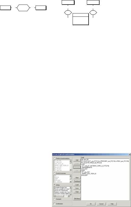
Figure 3. A typical schema transformation that replaces a many-to-many relationship type with an entity type and one-to-many relationship types
PRODUCT |
COUNTRY |
PRODUCT |
0-N |
export |
COUNTRY |
|
0-N |
0-N |
0-N |
||||||
|
|
Yearly Qty |
|
|
|
to |
of |
EXPORT
Yearly Qty
1-1
 1-1 id: to.PRODUCT
of.COUNTRY
into relationship types or into attributes, and to split/ merge entity types. Attributes can be transformed into entity types and relationship types. Compound attributes can be disagregated, while multivalued attributes can also be replaced with serial or concatenated attributes. Nonset attributes, such as bags, lists, and arrays, can be transformed into pure sets. Most of them are semanticspreserving, i.e., both source and resulting schemas describe exactly the same information (see Figure 3).
DB-MAIN introduces the concept of predicate-driven transformation, noted T(p), where T is any basic transformation and p a structural predicate as described in the previous section. Let us consider:
•RT_into_ET that denotes the transformation of a relationship type into an entity type (see Figure 3);
•expression ATT_per_RT(i j), a predicate that, when applied to a relationship type, checks whether the number of its attributes is between i and j; and
•expression ROLE_per_RT(i j), a predicate that, when applied to a relationship type, checks whether the number of its roles is between i and j.
Then, the expression
RT_into_ET(ATT_per_RT(1 N) or ROLE_per_RT(3 N))
defines a predicate-driven transformation the effect of which, when executed on the current schema, replaces all complex relationship types (i.e., those which have attributes or at least three roles) by entity types.
The most powerful application of this concept is the model-driven transformation. It consists of a chain of possibly iterative, predicate-driven transformations that is intended to transform any schema into a schema that complies with a definite model.
Both predicate-driven and model-driven transformations can be built, executed, saved, and reused through the Advanced Transformation Assistant of DB-MAIN. A dozen of popular, model-based, predefined transformations are provided to derive relational, XML, and UML schemas, but also to extract conceptual schemas from
DBMS schemas such as CODASYL and standard file managers. Figure 4 shows a fragment of a script that expresses an RDBMS transformation. Though strongly simplified (the complete script comprises about 20 predicate-driven transformations), this fragment includes the most important operators to transform conceptual schemas into relational structures:
•materializing IS-A relations into one-to-one relationship types (ISA_into_RT),
•transforming complex relationship types (i.e., with attributes, or with methods, or with at least three roles) into entity types (RT_into_ET),
•same for many-to-many relationship types (with two many roles),
•transforming multivalued attributes (the maximum cardinality of which is at least two) into entity types (ATT_into_ET),
•decomposing compound attributes (DISAGGREGATE),
•applying (LOOP) the latter two until everything has been transformed,
Figure 4. The main screen of the Schema Transformation Assistant of DB-MAIN; the script shown is a fragment of the ERA-to-relational model transformation
62
TEAM LinG

CASE Tools for Database Engineering
•expressing remaining relationship types into referalso provide some elementary transformations to produce
|
ential attributes, i.e., foreign keys (RT_into_REF), |
a basic conceptual schema, mainly by replacing foreign |
C |
|||||
• |
where the latter fails, adding a technical primary key |
keys by relationship types. However, such an approach |
|
|||||
|
||||||||
|
to |
the |
concerned |
entity |
type |
falls short for most actual databases. Indeed, it is based |
|
|
|
(SMART_ADD_TECH_ID), and |
|
on a oversimplistic hypothesis according to which the |
|
||||
• |
applying (LOOP) the latter two until everything |
conceptual schema has been completely expressed through |
|
|||||
|
has been transformed. |
|
|
explicitly declared SQL constructs, and, conversely, the |
|
|||
Code Generation |
|
|
conceptual schema only includes constructs that can be |
|
||||
|
|
declared through SQL statements. |
|
|||||
|
|
|
|
|
|
Unfortunately, most existing databases do not meet |
|
|
A schema that complies with the physical model of a |
this requirement. On the one hand, they often use legacy |
|
||||||
technologies, such as RPG, CODASYL, IMS, IMAGE, |
|
|||||||
DBMS can be transformed into a DDL script, the execu- |
|
|||||||
or COBOL files, for which few robust extractors have |
|
|||||||
tion of which will create the database structures. All |
|
|||||||
been developed. On the other hand, many constructs and |
|
|||||||
CASE tools include generators for a wide list of SQL |
|
|||||||
constraints have not been translated into DDL code, but |
|
|||||||
DBMSs. Theoretically, this should be straightforward |
|
|||||||
rather coded in the application programs, notably in data |
|
|||||||
since basic generators are fairly easy to develop and since |
|
|||||||
validation sections scattered through millions of lines |
|
|||||||
most DBMSs are SQL2 compliant. The hard problem is to |
|
|||||||
of code. Discovering them involves in-depth procedural |
|
|||||||
translate all the constructs of the conceptual schema into |
|
|||||||
code analysis that is out of the scope of standard text and |
|
|||||||
a poor DDL. This means not only that the logical and |
|
|||||||
character stream analyzers. Finally, many database struc- |
|
|||||||
physical schemas express these constructs, but also that |
|
|||||||
tures |
are not a straighforward translation of a clean |
|
||||||
the DDL generator is able to compensate for the weak- |
|
|||||||
conceptual schema, but include complex optimization |
|
|||||||
nesses of the target DDL. For instance, IS-A hierarchies |
|
|||||||
patterns that often are difficult to identify and interpret. |
|
|||||||
are not correctly translated by most popular SQL genera- |
|
|||||||
DB-MAIN(Hainaut,Englebert,Henrard,Hick&Rolans, |
|
|||||||
tors, |
and many useful constraints are ignored |
in the |
|
|||||
1996) includes a powerful tool set for large database |
|
|||||||
generation process. Consequently, the developer has to |
|
|||||||
reverse engineering. In particular it offers DDL code |
|
|||||||
manually modify the DDL code to translate the discarded |
|
|||||||
extractors for SQL, RPG, IMS, CODASYL (IDMS and |
|
|||||||
constructs, thus breaking the traceability chain between |
|
|||||||
IDS2), COBOL files, and XML; programmable text analyz- |
|
|||||||
the conceptual schema and the SQL code. |
|
|
||||||
|
ers to identify programming clichés; dependency and |
|
||||||
DB-MAIN offers a collection of basic generators for |
|
|||||||
dataflow graph analyzers; and a sophisticated program |
|
|||||||
SQL2 (including Oracle, Access, MySQL, and InterBase), |
|
|||||||
slicer to identify program sections that process database |
|
|||||||
COBOL files, CODASYL (IDS2), and XML (DTD and |
|
|||||||
components. It also includes specific assistants to dis- |
|
|||||||
Schema). It also includes a parametric SQL generator that |
|
|||||||
cover implicit foreigns keys and scripts to analyze large |
|
|||||||
takes in charge all the IS-A patterns as well as a large set |
|
|||||||
schemas and to extract conceptual structures from logical |
|
|||||||
of integrity constraints. The constructs that cannot be |
|
|||||||
schemas. The extensibility services of DB-MAIN make it |
|
|||||||
explicitly declared in SQL will be controlled through check |
|
|||||||
possible to develop additional tools to cope with new |
|
|||||||
predicates, views with check option, triggers, or stored |
|
|||||||
problems such as unknown legacy technologies. |
|
|||||||
procedures. |
|
|
|
|
|
|||
|
|
|
|
|
|
|
||
Some CASE tools also provide generators for DB- |
Meta-CASEs |
|
||||||
related code such as J2EE or .NET components, wrap- |
|
|||||||
pers, migrators, active components for special-purpose |
Strictly speaking, a meta-CASE is an environment in |
|
||||||
databases, or GUI to databases. |
|
|
|
|||||
|
|
|
|
|
|
which one can describe and generate customized CASE |
|
|
Reverse Engineering |
|
|
tools for a specific engineering area (Englebert & Hainaut, |
|
||||
|
|
|
|
|
|
1999; Kelly, Lyytinen, & Rossi, 1996). However, most |
|
|
The main goal of this process is to rebuild the logical and |
CASE tools offer some restricted capabilities for develop- |
|
||||||
ing additional specific, user-defined functions. |
|
|||||||
conceptual |
schemas |
of a legacy |
database, the |
docu- |
|
|||
DB-MAIN provides developers and method engi- |
|
|||||||
mentation of which is missing or outdated. Since it has |
|
|||||||
neers with five meta-level extensibility services. |
|
|||||||
been recognized that the availability of these schemas is |
|
|||||||
|
|
|
||||||
an absolute prerequisite in database maintenance, evolu- |
1. |
Method fragments (models and model-based trans- |
|
|||||
|
|
|
|
|
|
|
||
tion, migration, or federation, reverse engineering has |
formations) can be developed via the scripting |
|
gained increasing interest during the last decade. Most |
||
facility of the Schema Analysis and Global Trans- |
||
CASE tools are able to extract a graphical physical schema |
||
formation assistants. |
||
from the SQL code or from system catalog tables. They |
||
|
63
TEAM LinG
|
|
CASE Tools for Database Engineering |
2. |
The repository can be extended by associating |
Nevertheless, we can mention, among the main tools |
|
user-defined meta-properties with all the object |
at the present time, Rose and XDE from Rational, To- |
|
types. |
gether from Borland, PowerDesigner from Sybase, |
3.New processors and functions can be developed ERwin from Computer Associates, MEGA Database either in Java or through the 4GL Voyager 2. from MEGA International, MetaEdit+, a meta-CASE
4.After and before triggers can be defined for all the repository modification and transformation primitives.
5.MDL, a method engineering environment, allows companies to develop specific methodologies (Roland, Hainaut, Hick, Henrard, & Englebert, 2000). A method comprises specific models, product types, and engineering processes defined by their strategies. The method engine of DB-MAIN guarantees the strict application of the chosen methodology. It also ensures complete traceability thanks to its history manager.
For instance, customized versions of DB-MAIN have been developed for data warehouse design, database evolution, database reverse engineering, active database generation, XML engineering, federated database development and generation, and temporal database design and generation.
FUTURE TRENDS
Despite much effort from laboratories and industry (ISDOS, one of the first CASE tools was developed by Teichrow and Hershey in 1977), CASE tools are permeating more slowly than expected among practitioners. In their in-depth analysis, Lundell and Lings (2004) identify three factors that can explain this phenomenon but fail to spot the poor quality of the artefacts and code that CASE tools produce from users’ specifications.
Future tools are expected to provide better code generators; tools interoperability, notably through the CDIF (ISO, 2000); and XMI standards, intelligent assistance, and support for maintenance and evolution. Intermodel synchronization and transformational approaches will be better supported, as witnessed by the increasing popularity of the OMG MDA.
CONCLUSION
from MetaCase, Designer/2000 and Developer/2000 from Oracle, and Silverrun from Magna Solutions. Interested readers can also consult the site http:// www . qucis . queensu . ca/Software - Engineering/ tools.html. Information on DB-MAIN can be found at http://www.info.fundp.ac.be/libd. The free education edition can also be downloaded from this address.
REFERENCES
Batini, C., Ceri, S., & Navathe, S. B. (1992). Conceptual database design: An entity-relationship approach. Redwood City, CA: Benjamin Cummings.
Englebert, V., & Hainaut, J.-L. (1999). DB-MAIN: A next generation meta-CASE. Information Systems Journal,
24(2).
Hainaut, J.-L. (1996). Specification preservation in schema transformations—Application to semantics and statistics. Data & Knowledge Engineering, 11(1).
Hainaut, J.-L. (2005). Transformation-based database engineering.
Hainaut, J.-L., Englebert, V., Henrard, J., Hick J.-M., & Roland, D. (1996). Database reverse engineering: From requirements to CASE tools. Journal of Automated Software Engineering, 3(1).
ISO. (2000). Information technology—CDIF frame- work—Part 1: Overview (ISO/IEC FDIS 15474-1, Final Draft, ISO/IEC JTC 1/SC7/WG11, 2000-02-14).
Kelly, S., Lyytinen, K., & Rossi, M. (1996). MetaEdit+: A fully configurable multi-user and multi-tool CASE and CAME environment. In P. Constantopoulos, J. Mylopoulos, & Y. Vassiliou (Eds.), Lecture notes in computer science: Vol. 1080. Proceedings of CAiSE’96. Berlin/Heidelberg, Germany: Springer-Verlag.
Lundell, B., & Lings, L. (2004). Changing perceptions of CASE technology. Journal of Systems and Software,
72(2).
Any attempt to write a stable state of the art in database CASE technology would be hopeless. Indeed, this domain is highly volatile (Lundell & Lings, 2004) and is the subject of rapid merging and buying, so that even the name of well-established CASE tools can change in a short time.
Object Management Group. (2003, May). XML Metadata Interchange (XMI), v2.0. Retrieved September 2004 from http://www.omg.org/cgi-bin/doc?formal/2003-05-02
Roland, D., Hainaut, J.-L., Hick, J.-M., Henrard, J., & Englebert, V. (2000). Database engineering processes
64
TEAM LinG

CASE Tools for Database Engineering
with DB-MAIN. In Proceedings of the eighth European Conference on Information Systems (ECIS2000), Vienna University, Austria (Vol. 2, pp. 244-251).
Rosenthal, A., & Reiner, D. (1994). Tools and transforma- tions—rigourous and otherwise—for practical database design. ACM TODS, 19(2).
Teichrow, D., & Hershey, E. (1977). PSL/PSA: A computer aided technique for structured documentation and analysis of imformation processing systems. IEEE TOSE, 3(1).
van Bommel, P. (Ed.). (2004). Transformation of knowledge, information and data: Theory and applications. Hershey, PA: Infosci.
KEY TERMS
CASE Tool: Software tools that help software designers and developers specify, generate, and maintain some or all software components of an application. Most CASE tools provide functions to allow developers to draw database schemas and to generate the corresponding DDL code.
Conceptual Schema: A structured technology-in- dependent description of the information about an application domain such as a company or a library. By extension, it is also an abstract representation of the existing or project database that is made up of the data of this domain.
Database Reverse Engineering: The process through which the logical and conceptual schemas of a legacy database or of a set of files are recovered or rebuilt from various information sources such as DDL code, data dictionary contents, database contents, or the source code of application programs that use the database.
DB-MAIN:An experimental CASE tool in development at the University of Namur since 1993. It supports most database engineering processes, among them, information analysis, database design, reverse engineering, federated database design, and database migration. Its generic structure model and method engineering environment allow users to build their own methodologies.
Logical Schema: The description of the data struc-
tures of a database according to the model of a specific C technology, e.g., a RDBMS. The logical schema of a database is the implementation of its conceptual schema. Application programs know the database through its logical schema.
Models and Schemas: In the database realm, a model M is a formal system comprising a closed set of abstract object categories and a set of assembly rules that states which arrangements of objects are valid. Since M is supposed to describe the structure, the properties, and the behaviour of a class S of external systems, the semantics of M is specified by a mapping of M onto S. Any arrangement m of objects which is valid according to M describes a specific system s of class S. m is called a schema while s is the application domain or the universe of discourse. Among the most popular conceptual models we can mention the entity-relationship, object-role, relational, and UML class models. Among DBMS models, the SQL, CODASYL, IMS, object-relational, and XML models are curently the most widely used.
Physical Schema: The technical description of a database; all the physical constructs (such as indexes) and parameters (such as page size or buffer management policy) are specified. The physical schema of a database is the implementation of its logical schema.
Repository: A database in which the specification and the description of the various artefacts of a software system are stored. As far as database engineering is concerned, the repository includes the schemas of the project database at all the abstraction levels as well as the correspondence between them. All CASE tools rely on some sort of repository.
Traceability: The property of software design and development that makes it possible to link any abstract artefact to the technical artefacts that implement it and conversely. In addition, this link explains how and why this implementation has been chosen. In the database realm, traceability allows a programmer to know exactly which conceptual object a definite column is an implemention of. Conversely, it informs him/her on how a conceptual relationship type has been implemented. The transformational paradigm is one of the most promising approaches to formally guarantee traceability.
65
TEAM LinG
66
Checking Integrity Constraints in a
Distributed Database
Hamidah Ibrahim
Universiti Putra Malaysia, Malaysia
INTRODUCTION
Preserving the accuracy and the integrity of information in a database is extremely important for the organization that is maintaining that database. Such an organization is likely to rely heavily upon that accuracy. Applications that consult and use the database expect a guarantee that the database is supplying the correct information. Critical business decisions may be made assuming that information extracted from the database is correct. Thus, incorrect data can lead to incorrect business decisions, which can have serious implications for the people and organizations using it (Codd, 1990).
An important problem for a database system is to guarantee database consistency. Many techniques and tools have been devised to fulfill this requirement in many interrelated research areas, such as concurrency control, security control, reliability control and integrity control (Eswaran & Chamberlin, 1975; Grefen, 1993). Concurrency control deals with prevention of inconsistencies caused by concurrent access by multiple users or applications to a database. Security control deals with preventing users from accessing and modifying data in a database in unauthorized ways. Reliability control deals with the prevention errors due to the malfunctioning of system hardware or software. Integrity control deals with the prevention of semantic errors made by the users due to their carelessness or lack of knowledge.
A database state is said to be consistent if the database satisfies a set of statements, called semantic integrity constraints (or simply constraints). Integrity constraints specify those configurations of the data that are considered semantically correct. Any update operation (insert, delete, or modify) or transaction (sequence of updates) that occurs must not result in a state that violates these constraints. Thus, a fundamental issue concerning integrity constraints is constraint checking, that is the process of ensuring that the integrity constraints are satisfied by the database after it has been updated. Checking the consistency of a database state will generally involve the execution of integrity tests on the database which verify whether the database is satisfying its constraints or not.
In a database system, a semantic integrity subsystem (SIS) is responsible for managing and enforcing integrity constraints to ensure that these rules are not violated by the database and the database is in a consistent state. An early proposal by Eswaran and Chamberlin (1975) described the functionality requirements for an integrity subsystem. The main tasks of this subsystem are to determine which constraints are to be checked after each database change and to trigger the appropriate actions when a constraint violation is detected. The crucial problem encountered in designing a complete integrity subsystem is the difficulty of devising an efficient algorithm for enforcing database integrity when updates occur. Many proposals for designing an integrity subsystem can be found in the database literature. In Grefen (1993) and McCarroll (1995) three ways to couple the integrity subsystem to the database management system (DBMS) are described.
The first approach is known as the decoupled subsystem approach. This adds the subsystem as an additional layer on top of an existing DBMS. It was employed by the AIM project (Cremers & Domann, 1983) and the KBDTA system (Wang, 1992). In this approach, the responsibility for ensuring the consistency of the database when a transaction occurs is part of the transaction design process. The transaction designers are responsible for ensuring that the transactions are safe (i.e., when executed, the transactions are guaranteed to bring the database from one consistent state to another consistent state). Consequently, as transactions can get complex, a transaction design tool is usually incorporated into the subsystem to assist the transaction designers to construct safe transactions. Hence, in this approach, little or no support within the DBMS is needed for automatically enforcing database integrity constraints.
The second approach is known as the loosely coupled subsystem. It adds the subsystem as an extension to the DBMS. This is employed by the SABRE (Simon & Valduriez, 1987) and the PRISMA (Grefen, 1990) projects. In this approach, transactions have integrity tests embedded in them to perform the necessary integrity checking. The modified transactions can then be executed by the standard transaction facilities. This
Copyright © 2006, Idea Group Inc., distributing in print or electronic forms without written permission of IGI is prohibited.
TEAM LinG

Checking Integrity Constraints in a Distributed Database
approach is based on query modification and transaction modification strategies, where an arbitrary query or transaction that may violate the integrity of a database is modified, such that the execution of the modified query or transaction is assured to leave the database in a consistent state.
In the third approach, which is known as the tightly coupled subsystem, the subsystem is seen as part of the basic functionality of a database system and is fully integrated into it. This approach, initially proposed by Hammer and McLeod (1975) and Eswaran and Chamberlin (1975), is employed by the Starbust project (Ceri, Fraternali, Paraboschi, & Tanca, 1994), SICSDD project (Ibrahim, Gray, & Fiddian, 1998) and the latest versions of commercial DBMSs, such as INGRES and ORACLE. In this approach, integrity tests are general rather than transaction specific and thus no knowledge of the internal structure of a transaction is required. Typically, this requires rule mechanisms to implement integrity constraint enforcement (Ibrahim, 2002a).
BACKGROUND
The growing complexity of modern database applications plus the need to support multiple users has further increased the need for a powerful integrity subsystem to be incorporated into these systems. Therefore, a complete integrity subsystem is considered to be an important part of any modern DBMS (Grefen, 1993). The crucial problem in designing a complete integrity subsystem is the difficulty of devising an efficient algorithm for enforcing database integrity against updates. Thus, it is not surprising that much attention has been paid to the maintenance of integrity in centralized databases over the last decade. A naive approach is to perform the update and then check whether the integrity constraints are satisfied in the new database state. This method, termed brute force checking, is very expensive, impractical and can lead to prohibitive processing costs (Embury, Gray, & Bassiliades, 1993; Hsu & Imielinski, 1985; Mazumdar, 1993, Plexousakis, 1993; Qian, 1988, 1989; Sheard & Stemple, 1989). Enforcement is costly because the evaluation of integrity constraints requires accessing large amounts of data which are not involved in the database update transition (Simon & Valduriez, 1987). Hence, improvements to this approach have been reported in many research papers (Bernstein & Blaustein, 1981; Blaustein, 1981; Henschen, McCune, & Naqvi, 1984; Hsu & Imielinski, 1985; McCune & Henschen, 1989; Nicolas, 1982; Qian, 1989). Although this research effort has yielded fruitful results that have given centralized systems a substantial level of reliability and robustness with respect to the
integrity of their data, there has so far been little research carried out on integrity issues for distributed C databases. The problem of devising an efficient enforcement mechanism is more crucial in a distributed environment. This is due to the following facts (Barbara
& Garcia-Molina, 1992; Mazumdar, 1993; Qian 1989; Simon & Valduriez, 1987):
•Integrity constraints are general statements about sets of data elements which may spread over several sites in a distributed database. A large amount of data may therefore need to be transferred around the network in order to determine the truth of such statements.
•Owing to the possibility of fragmentation of relations with the fragments stored at different locations, the integrity constraints must be transformed into constraints on the fragments so that they can be straightforwardly used for constructing efficient enforcement algorithms. Thus, there are usually more integrity constraints in an equivalent distributed database than a centralized database, all of which need to be maintained. In addition, replication of data imposes an additional constraint that the replicas must have equivalent values at all times.
•Frequent updates can lead to frequent executions of expensive violation testing operations.
•If some constraints are violated, the whole update transaction which causes the state transition must be aborted and the database must be restored to the previous state, which can be a very costly operation in a distributed system.
The brute force strategy of checking constraints is worse in the distributed context since the checking would typically require data transfer as well as computation leading to complex algorithms to determine the most efficient approach. Allowing an update to execute with the intention of aborting it at commit time in the event of constraint violation is also inefficient since rollback and recovery must occur at all sites which participated in the update. Thus, the question of interest is how to efficiently check integrity constraints in a distributed environment.
Many researchers have studied the problem of maintaining the consistency of a database and not surprisingly many different approaches have been proposed. For centralized databases, researchers have suggested that constraint checking can be optimized by exploiting the fact that the constraints are known to be satisfied prior to an update, and by reducing the number of integrity constraints that need checking by only checking the subset of integrity constraints that may be vio-
67
TEAM LinG
Checking Integrity Constraints in a Distributed Database
lated by the current update or transaction. This is based on the following observation by Nicolas (1982). Given a valid database state, a new state is obtained when it is updated either by a single update operation or by a transaction. Depending on the operation leading to the new state, some integrity constraints remain necessarily satisfied in this new state, while others have to be evaluated to determine whether they are actually satisfied or not (Nicolas, 1982). Thus an integrity testing strategy which avoids redundantly checking constraints that are satisfied in the database before and are not affected by the update operation is better (more efficient) than a basic strategy which checks all the constraints. This revised strategy, known as incremental integrity checking (Gupta, 1994, Plexousakis, 1993) or constraint filtering (Grefen, 1990), is the basis of most current approaches to integrity checking in databases. In Gupta (1994), this strategy is also referred to as a brute force strategy because by default it uses all the underlying relations.
Another strategy is to simplify the constraint formulae so that less data are accessed in order to determine the truth of the constraint. With the assumption that the set of initial constraints (IC), is known to be satisfied in the state before an update, simplified forms of IC, say IC’, are constructed such that IC is satisfied in the new state if and only if IC’ is satisfied, and the evaluation cost of IC’ is less than or equal to the evaluation cost of IC. This strategy is referred to as constraint simplification and the simplified forms of these constraints are referred to as integrity tests (Ibrahim, 2002b; Ibrahim, Gray & Fiddian, 1996; McCarroll, 1995) or constraint protectors (Stemple, Mazumdar, & Sheard, 1987). This approach conforms to the admonition of Nicolas (1982) to concentrate on the problem of finding good constraints. Various simplification techniques have been proposed where integrity tests are derived from the syntactic structure of the constraints and the update operations (Bernstein & Blaustein, 1981; Blaustein, 1981; Gupta, 1994; Henschen, McCune, & Naqvi, 1984; Hsu & Imielinski, 1985, McCarroll, 1995, McCune & Henschen, 1989; Nicolas, 1982; Qian, 1989; Simon & Valduriez, 1987). These techniques are referred to as constraint simplification by update analysis. Researchers in this area have focused solely on the derivation of efficient integrity tests, claiming that they are cheaper to enforce and reduce the amount of data accessed, thus reducing the cost of integrity constraint checking. Three different types of integrity test are defined in McCune and Henschen (1989), namely, sufficient tests, necessary tests, and complete tests. An important property desired of an integrity test of any of these three types is that the test will be cheaper to execute than the initial constraint from which it is derived. Thus, it is important to ensure that such integrity tests are as efficient as possible in
order to reduce the performance overheads imposed by integrity enforcement. The issue addressed here is how to derive an efficient set of tests to prove that an update operation will guarantee the semantic integrity of the database with respect to each and every constraint defined on the database.
Furthermore, to avoid undoing the updates, these tests must be evaluated before the database state transition caused by the update occurs. The introduction of inconsistencies in the database is therefore prevented by committing only those update operations that result in a consistent database state. Methods following this approach are term preventive methods and are favoured over detective methods, which allow an update operation to be executed on a database state and when an inconsistent result state is detected undo this update.
For distributed database environments, most of the strategies proposed for centralized systems are used, in particular the incremental integrity checking strategy and the constraint simplification method strategy, which aim to reduce the number of integrity constraints to be evaluated and the amount of data accessed. In addition, new strategies appropriate to a distributed environment have been proposed which aim to reduce the number of sites involved and thus reduce the amount of data transferred across the network (Barbara & Garcia-Molina, 1992; Gupta, 1994; Ibrahim, Gray & Fiddian, 1998; Mazumdar, 1993; Qian, 1989). These strategies try to avoid remote accesses to the update sites (target sites) and are invaluable in a situation where it is impossible to access data located at other sites in the distributed system, for example in situations where network failure is detected, or a high-security database is involved. This means identifying how to simplify the integrity constraints so that evaluation is more local and at best is entirely local to the sites involved in the update.
Although the performance of constraint checking in a distributed database system has been improved by adopting the centralized strategies, with respect to the amount of data accessed or transferred, the following strategies are still inefficient for distributed environments:
i.Most of the simplified forms are derived from the initial constraints as specified by the user. These derivations do not exploit knowledge about the database application, especially its data fragmentation and allocation, which can be used to
a.derive a set of simplified constraints that can be straightforwardly used for constructing efficient enforcement algorithms with respect to the distributed environment, and
68
TEAM LinG

Checking Integrity Constraints in a Distributed Database
b.infer the information stored at different sites of the network and so minimize the support from remote sites required when checking the constraints.
ii.Complete tests, which are the tests used most often in centralized systems, are usually expensive in a distributed environment. However, sufficient tests are useful in a distributed environment (Mazumdar, 1993) because their checking space often only spans a single site and therefore they can be performed at a reasonable cost as the number of sites involved and the amount of data transferred across the network are reduced.
The problem of choosing a good set of constraints for better enforcement that has been explored intensively in centralized systems has been relatively neglected for distributed systems.
Constraint simplification methods in a distributed environment can be classified into two types of approach. Both approaches are targeted at deriving integrity tests/conditions, but they use different information. The first approach uses knowledge about the application domain and data fragmentation (Mazumdar, 1993; Qian, 1989). This approach is referred to as constraint simplification by reformulation. The second approach analyses the syntactic structure of the constraints and the update operations in order to generate the integrity tests, as reported in Gupta (1994), and is referred to as constraint simplification by update analysis.
STRATEGIES FOR CHECKING INTEGRITY CONSTRAINTS IN A DISTRIBUTED DATABASE
In order to improve and to generate an efficient integrity constraint checking in a distributed environment the following circumstances should be undertaken.
i.Constraint Filtering: It assumes that the database is consistent prior to an update and an incremental integrity checking strategy is adopted which reduces the number of constraints evaluated. For each update request, only those constraints that may be violated by it are selected for further evaluation. This can be performed by observing the following rules where integrity constraints are specified in prenex conjunctive normal form.
a.Whenever an update operation is dealing with the extension of a relation R, integrity con-
straints in which R does not occur are unaf- |
C |
fected. |
b.Integrity constraints which do not contain R in negated atomic formula are unaffected when a tuple is inserted into the extension of R.
c.Integrity constraints which do not contain R in a nonnegated atomic formula are unaffected when a tuple is deleted from the extension of R.
Also, by rescheduling the execution of the integrity rules, early update abortion in the case of constraint violation is effected. Detecting constraint violation as early as possible is important since it eliminates the execution of further integrity rules and thus reduces the execution time of the process. Some heuristic rules can be applied, such as the following:
a.Choose an integrity constraint (rule) whose violation implies that no other integrity constraints are triggered, i.e. an isolated node in the triggering graph. For example, an integrity rule for a key constraint with an ABORT action. This is because inserting a new tuple which violates a key constraint implies that no insertion should be made at all.
b.Choose a local rule, i.e. an integrity rule that can be performed at a local site.
c.An integrity rule with test Ti which subsumes another integrity rule with test Tj is preferred since the truth of test Ti implies the truth of test
Tj.
ii.Constraint Optimization: Because the enforcement of the constraints takes place at the fragment level, the constraints specified in terms of global relations should be transformed into constraints specified in terms of fragment relations so that they can be straightforwardly used for constructing efficient enforcement algorithms. Here, efficient means a set of fragment constraints, which is semantically equivalent to the initial set, does not contain any semantic or syntactically redundant fragment constraints/constructs, eliminates any fragment constraints whose evaluation is proven to be true, eliminates any fragment constraints which contradict already existing fragmentation rules and whose derived constraints are either more local (less distributed) or are entirely local when compared with the initial set. Thus, the properties that one should look for in the derived fragment constraints are that they are more efficient and more local than the initial set of constraints. Most of the previous approaches/methods proposed for finding/deriving a good set of constraints concentrate on deriving
69
TEAM LinG