

- •Radio Engineering for Wireless Communication and Sensor Applications
- •Contents
- •Preface
- •Acknowledgments
- •1 Introduction to Radio Waves and Radio Engineering
- •1.1 Radio Waves as a Part of the Electromagnetic Spectrum
- •1.2 What Is Radio Engineering?
- •1.3 Allocation of Radio Frequencies
- •1.4 History of Radio Engineering from Maxwell to the Present
- •2.2 Fields in Media
- •2.3 Boundary Conditions
- •2.4 Helmholtz Equation and Its Plane Wave Solution
- •2.5 Polarization of a Plane Wave
- •2.6 Reflection and Transmission at a Dielectric Interface
- •2.7 Energy and Power
- •3 Transmission Lines and Waveguides
- •3.1 Basic Equations for Transmission Lines and Waveguides
- •3.2 Transverse Electromagnetic Wave Modes
- •3.3 Transverse Electric and Transverse Magnetic Wave Modes
- •3.4 Rectangular Waveguide
- •3.4.1 TE Wave Modes in Rectangular Waveguide
- •3.4.2 TM Wave Modes in Rectangular Waveguide
- •3.5 Circular Waveguide
- •3.6 Optical Fiber
- •3.7 Coaxial Line
- •3.8 Microstrip Line
- •3.9 Wave and Signal Velocities
- •3.10 Transmission Line Model
- •4 Impedance Matching
- •4.1 Reflection from a Mismatched Load
- •4.2 Smith Chart
- •4.3 Matching Methods
- •4.3.1 Matching with Lumped Reactive Elements
- •4.3.4 Resistive Matching
- •5 Microwave Circuit Theory
- •5.1 Impedance and Admittance Matrices
- •5.2 Scattering Matrices
- •5.3 Signal Flow Graph, Transfer Function, and Gain
- •6.1 Power Dividers and Directional Couplers
- •6.1.1 Power Dividers
- •6.1.2 Coupling and Directivity of a Directional Coupler
- •6.1.3 Scattering Matrix of a Directional Coupler
- •6.1.4 Waveguide Directional Couplers
- •6.1.5 Microstrip Directional Couplers
- •6.2 Ferrite Devices
- •6.2.1 Properties of Ferrite Materials
- •6.2.2 Faraday Rotation
- •6.2.3 Isolators
- •6.2.4 Circulators
- •6.3 Other Passive Components and Devices
- •6.3.1 Terminations
- •6.3.2 Attenuators
- •6.3.3 Phase Shifters
- •6.3.4 Connectors and Adapters
- •7 Resonators and Filters
- •7.1 Resonators
- •7.1.1 Resonance Phenomenon
- •7.1.2 Quality Factor
- •7.1.3 Coupled Resonator
- •7.1.4 Transmission Line Section as a Resonator
- •7.1.5 Cavity Resonators
- •7.1.6 Dielectric Resonators
- •7.2 Filters
- •7.2.1 Insertion Loss Method
- •7.2.2 Design of Microwave Filters
- •7.2.3 Practical Microwave Filters
- •8 Circuits Based on Semiconductor Devices
- •8.1 From Electron Tubes to Semiconductor Devices
- •8.2 Important Semiconductor Devices
- •8.2.1 Diodes
- •8.2.2 Transistors
- •8.3 Oscillators
- •8.4 Amplifiers
- •8.4.2 Effect of Nonlinearities and Design of Power Amplifiers
- •8.4.3 Reflection Amplifiers
- •8.5.1 Mixers
- •8.5.2 Frequency Multipliers
- •8.6 Detectors
- •8.7 Monolithic Microwave Circuits
- •9 Antennas
- •9.1 Fundamental Concepts of Antennas
- •9.2 Calculation of Radiation from Antennas
- •9.3 Radiating Current Element
- •9.4 Dipole and Monopole Antennas
- •9.5 Other Wire Antennas
- •9.6 Radiation from Apertures
- •9.7 Horn Antennas
- •9.8 Reflector Antennas
- •9.9 Other Antennas
- •9.10 Antenna Arrays
- •9.11 Matching of Antennas
- •9.12 Link Between Two Antennas
- •10 Propagation of Radio Waves
- •10.1 Environment and Propagation Mechanisms
- •10.2 Tropospheric Attenuation
- •10.4 LOS Path
- •10.5 Reflection from Ground
- •10.6 Multipath Propagation in Cellular Mobile Radio Systems
- •10.7 Propagation Aided by Scattering: Scatter Link
- •10.8 Propagation via Ionosphere
- •11 Radio System
- •11.1 Transmitters and Receivers
- •11.2 Noise
- •11.2.1 Receiver Noise
- •11.2.2 Antenna Noise Temperature
- •11.3 Modulation and Demodulation of Signals
- •11.3.1 Analog Modulation
- •11.3.2 Digital Modulation
- •11.4 Radio Link Budget
- •12 Applications
- •12.1 Broadcasting
- •12.1.1 Broadcasting in Finland
- •12.1.2 Broadcasting Satellites
- •12.2 Radio Link Systems
- •12.2.1 Terrestrial Radio Links
- •12.2.2 Satellite Radio Links
- •12.3 Wireless Local Area Networks
- •12.4 Mobile Communication
- •12.5 Radionavigation
- •12.5.1 Hyperbolic Radionavigation Systems
- •12.5.2 Satellite Navigation Systems
- •12.5.3 Navigation Systems in Aviation
- •12.6 Radar
- •12.6.1 Pulse Radar
- •12.6.2 Doppler Radar
- •12.6.4 Surveillance and Tracking Radars
- •12.7 Remote Sensing
- •12.7.1 Radiometry
- •12.7.2 Total Power Radiometer and Dicke Radiometer
- •12.8 Radio Astronomy
- •12.8.1 Radio Telescopes and Receivers
- •12.8.2 Antenna Temperature of Radio Sources
- •12.8.3 Radio Sources in the Sky
- •12.9 Sensors for Industrial Applications
- •12.9.1 Transmission Sensors
- •12.9.2 Resonators
- •12.9.3 Reflection Sensors
- •12.9.4 Radar Sensors
- •12.9.5 Radiometer Sensors
- •12.9.6 Imaging Sensors
- •12.10 Power Applications
- •12.11 Medical Applications
- •12.11.1 Thermography
- •12.11.2 Diathermy
- •12.11.3 Hyperthermia
- •12.12 Electronic Warfare
- •List of Acronyms
- •About the Authors
- •Index
Applications |
353 |
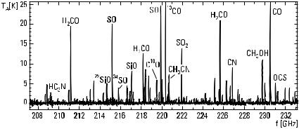
the spectral lines reveals the distribution of molecules and dynamics of clouds. Figure 12.30 shows a measured spectrum of a molecular cloud in Orion [15].
Pulsars, originally called pulsating stars, are swiftly rotating neutron stars. They emit radiation in two narrow beams that sweep space like the beams from a lighthouse. The periods of short pulses received from pulsars range from one-thousandth of a second to a few seconds. The periods are very stable but are in some cases increasing as the neutron star slows down.
Radio galaxies and quasars (quasistellar objects) are radio sources outside our galaxy. The nearest normal galaxies have been mapped using radio waves. The radio emission of an ordinary galaxy is only a small fraction of its optical emission. In radio galaxies, the intensities of radio and optical emissions are of the same order. Quasars look like point sources. Their optical spectra show such large red shifts or recession velocities that the most distant quasars must be located near the edge of the known universe, or they are seen as they looked in the early universe. The intensities of both optical and radio emissions change with periods as small as one day, indicating that the quasars are small. The huge radiation of such a small object can be explained only by assuming that matter is falling down a black hole.
12.9 Sensors for Industrial Applications
Microwaves can be used for many kinds of measurements in industry [16–19]. The electrical properties of matter determine how radio waves propagate in it and reflect from interfaces. Electrical properties in turn depend on physical properties such as moisture, density, composition, and temperature. The
Figure 12.30 Spectral lines of an interstellar molecular cloud. (After: [15].)

354 Radio Engineering for Wireless Communication and Sensor Applications
advantages of microwave sensors are that measurements can be carried out without touching the object and that microwaves penetrate into the material. Different types of sensors and their applicability are treated here.
12.9.1 Transmission Sensors
A typical transmission sensor has two horn antennas, a transmitter, and a receiver. Waves pass through the object placed between the antennas. The phase shift due to the change in propagation velocity and the attenuation due to loss in the material are measured. Transmission sensors are simple and can be used for the measurement of materials moving on a conveyor belt, for example, or in a large tube. They are used to measure the moisture content of grain, coal, sand, and so on.
12.9.2 Resonators
A microwave resonator may be a cavity, strip-line, slot-line, parallel-wire line, or coaxial-line resonator. Resonators based on a slot or parallel-wire line may be used to measure liquid, granular, or pasty materials. Stripline resonators are suitable for measuring sheets and material layers. Cavity resonators may be used as gas analyzers and to measure bars and materials flowing in tubes. Resonators may be used for many kinds of measurements: the moisture content of paper (see Figure 12.31), veneer, and air, the thickness of paper mass, the fiber orientation in paper, the thickness of plastic bars
Figure 12.31 Strip-line resonator array for measuring paper moisture profile. (After: [17].)
Applications |
355 |
and metal sheets, the burning energy value of peat, the water content of snow, and so on.
12.9.3 Reflection Sensors
The complex reflection coefficient of an object depends on the relative permittivity er and its distribution within a few skin depths from the surface. If the object is layered, the thickness and permittivity of the layers may be solved from the frequency response of the reflection coefficient. An open end of a coaxial cable or waveguide, which is pressed on the surface of the object, is a simple reflection sensor. The reflection coefficient depends on the end capacitance and conductance, which in turn are functions of er . Measurement of ground moisture and testing of materials are applications of reflection sensors.
12.9.4 Radar Sensors
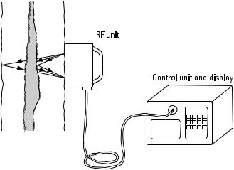
Radar sensors can measure the amplitude of reflection, propagation time, or Doppler shift. Applications of radar sensors are numerous: door openers, movement detectors in burglar alarms, surface height detectors in vessels (applicable also when there is danger of explosion or foam on the surface), measuring power line vibrations, detecting rot in trees (see Figure 12.32), detecting pipes, cables, ancient relics, and mines in the ground, measuring marsh depth, and more.
Figure 12.32 Impulse radar used to measure rot in trees.