- •Radio Engineering for Wireless Communication and Sensor Applications
- •Contents
- •Preface
- •Acknowledgments
- •1 Introduction to Radio Waves and Radio Engineering
- •1.1 Radio Waves as a Part of the Electromagnetic Spectrum
- •1.2 What Is Radio Engineering?
- •1.3 Allocation of Radio Frequencies
- •1.4 History of Radio Engineering from Maxwell to the Present
- •2.2 Fields in Media
- •2.3 Boundary Conditions
- •2.4 Helmholtz Equation and Its Plane Wave Solution
- •2.5 Polarization of a Plane Wave
- •2.6 Reflection and Transmission at a Dielectric Interface
- •2.7 Energy and Power
- •3 Transmission Lines and Waveguides
- •3.1 Basic Equations for Transmission Lines and Waveguides
- •3.2 Transverse Electromagnetic Wave Modes
- •3.3 Transverse Electric and Transverse Magnetic Wave Modes
- •3.4 Rectangular Waveguide
- •3.4.1 TE Wave Modes in Rectangular Waveguide
- •3.4.2 TM Wave Modes in Rectangular Waveguide
- •3.5 Circular Waveguide
- •3.6 Optical Fiber
- •3.7 Coaxial Line
- •3.8 Microstrip Line
- •3.9 Wave and Signal Velocities
- •3.10 Transmission Line Model
- •4 Impedance Matching
- •4.1 Reflection from a Mismatched Load
- •4.2 Smith Chart
- •4.3 Matching Methods
- •4.3.1 Matching with Lumped Reactive Elements
- •4.3.4 Resistive Matching
- •5 Microwave Circuit Theory
- •5.1 Impedance and Admittance Matrices
- •5.2 Scattering Matrices
- •5.3 Signal Flow Graph, Transfer Function, and Gain
- •6.1 Power Dividers and Directional Couplers
- •6.1.1 Power Dividers
- •6.1.2 Coupling and Directivity of a Directional Coupler
- •6.1.3 Scattering Matrix of a Directional Coupler
- •6.1.4 Waveguide Directional Couplers
- •6.1.5 Microstrip Directional Couplers
- •6.2 Ferrite Devices
- •6.2.1 Properties of Ferrite Materials
- •6.2.2 Faraday Rotation
- •6.2.3 Isolators
- •6.2.4 Circulators
- •6.3 Other Passive Components and Devices
- •6.3.1 Terminations
- •6.3.2 Attenuators
- •6.3.3 Phase Shifters
- •6.3.4 Connectors and Adapters
- •7 Resonators and Filters
- •7.1 Resonators
- •7.1.1 Resonance Phenomenon
- •7.1.2 Quality Factor
- •7.1.3 Coupled Resonator
- •7.1.4 Transmission Line Section as a Resonator
- •7.1.5 Cavity Resonators
- •7.1.6 Dielectric Resonators
- •7.2 Filters
- •7.2.1 Insertion Loss Method
- •7.2.2 Design of Microwave Filters
- •7.2.3 Practical Microwave Filters
- •8 Circuits Based on Semiconductor Devices
- •8.1 From Electron Tubes to Semiconductor Devices
- •8.2 Important Semiconductor Devices
- •8.2.1 Diodes
- •8.2.2 Transistors
- •8.3 Oscillators
- •8.4 Amplifiers
- •8.4.2 Effect of Nonlinearities and Design of Power Amplifiers
- •8.4.3 Reflection Amplifiers
- •8.5.1 Mixers
- •8.5.2 Frequency Multipliers
- •8.6 Detectors
- •8.7 Monolithic Microwave Circuits
- •9 Antennas
- •9.1 Fundamental Concepts of Antennas
- •9.2 Calculation of Radiation from Antennas
- •9.3 Radiating Current Element
- •9.4 Dipole and Monopole Antennas
- •9.5 Other Wire Antennas
- •9.6 Radiation from Apertures
- •9.7 Horn Antennas
- •9.8 Reflector Antennas
- •9.9 Other Antennas
- •9.10 Antenna Arrays
- •9.11 Matching of Antennas
- •9.12 Link Between Two Antennas
- •10 Propagation of Radio Waves
- •10.1 Environment and Propagation Mechanisms
- •10.2 Tropospheric Attenuation
- •10.4 LOS Path
- •10.5 Reflection from Ground
- •10.6 Multipath Propagation in Cellular Mobile Radio Systems
- •10.7 Propagation Aided by Scattering: Scatter Link
- •10.8 Propagation via Ionosphere
- •11 Radio System
- •11.1 Transmitters and Receivers
- •11.2 Noise
- •11.2.1 Receiver Noise
- •11.2.2 Antenna Noise Temperature
- •11.3 Modulation and Demodulation of Signals
- •11.3.1 Analog Modulation
- •11.3.2 Digital Modulation
- •11.4 Radio Link Budget
- •12 Applications
- •12.1 Broadcasting
- •12.1.1 Broadcasting in Finland
- •12.1.2 Broadcasting Satellites
- •12.2 Radio Link Systems
- •12.2.1 Terrestrial Radio Links
- •12.2.2 Satellite Radio Links
- •12.3 Wireless Local Area Networks
- •12.4 Mobile Communication
- •12.5 Radionavigation
- •12.5.1 Hyperbolic Radionavigation Systems
- •12.5.2 Satellite Navigation Systems
- •12.5.3 Navigation Systems in Aviation
- •12.6 Radar
- •12.6.1 Pulse Radar
- •12.6.2 Doppler Radar
- •12.6.4 Surveillance and Tracking Radars
- •12.7 Remote Sensing
- •12.7.1 Radiometry
- •12.7.2 Total Power Radiometer and Dicke Radiometer
- •12.8 Radio Astronomy
- •12.8.1 Radio Telescopes and Receivers
- •12.8.2 Antenna Temperature of Radio Sources
- •12.8.3 Radio Sources in the Sky
- •12.9 Sensors for Industrial Applications
- •12.9.1 Transmission Sensors
- •12.9.2 Resonators
- •12.9.3 Reflection Sensors
- •12.9.4 Radar Sensors
- •12.9.5 Radiometer Sensors
- •12.9.6 Imaging Sensors
- •12.10 Power Applications
- •12.11 Medical Applications
- •12.11.1 Thermography
- •12.11.2 Diathermy
- •12.11.3 Hyperthermia
- •12.12 Electronic Warfare
- •List of Acronyms
- •About the Authors
- •Index
7
Resonators and Filters
Transmission line and waveguide devices, discussed in Chapter 6, would ideally operate over a broad bandwidth. However, the useful bandwidth may be limited, for example, by the frequency dependence of the line sections that have proper electrical lengths only at the design frequency. Resonators and filters are intentionally frequency-selective devices.
7.1 Resonators
Resonators are used for stabilizing the frequency of oscillators, as building blocks of filters, as sensors in material measurements, and so on.
There are a large number of different resonator structures. Lumped components, coils and capacitors, are usable in realizing resonators at radio frequencies. Resonators based on the piezoelectric effect in a quartz crystal operate up to the VHF range. In micromechanical resonators made using microelectromechanical systems (MEMS) technology, electrical signals are coupled with the mechanical vibrations of a resonating beam [1]. Micromachined beam resonators may soon become usable at the UHF range. An opencircuited or short-circuited line, a closed metal cavity, a cylindrical pill made of a ceramic material, and a sphere made of ferrite (yttrium iron garnet, YIG) are examples of resonators operating at microwave frequencies. Open quasioptical resonators become usable in the millimeter-wave range and at higher frequencies.
141

142 Radio Engineering for Wireless Communication and Sensor Applications
7.1.1 Resonance Phenomenon
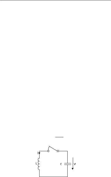
A resonator is a structure having a natural frequency of oscillation. A circuit consisting of a coil and a capacitor, shown in Figure 7.1, forms a simple electromagnetic resonator. At first the switch is open and the capacitor is charged to a voltage V. The electric field of the capacitor contains an energy of We = CV 2/2, where C is the capacitance of the capacitor. After the switch is closed, a current starts to flow through the coil. When the capacitor has completely discharged, the current I is at maximum and the whole energy of the circuit is in the magnetic field of the coil. This energy is Wm = LI 2/2, where L is the inductance of the coil. Then the current will again charge the capacitor, but now the polarity of the voltage is reversed. At resonance, the average energy in the electric field CV 2/4 is equal to the average energy in the magnetic field LI 2/4. The resonance frequency of the circuit is
f r = |
1 |
|
(7.1) |
|
|
||
|
|
||
|
2p √LC |
||
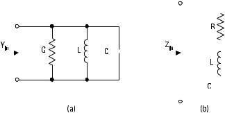
If energy is applied to the circuit from an external source at the resonance frequency and in the correct phase, the energy contained in the circuit will increase. However, due to losses in the circuit, the energy does not increase indefinitely. The losses are modeled with a conductance G in a parallel resonant circuit and with a resistance R in a series resonant circuit, as shown in Figure 7.2. Also, resonators made of transmission lines and waveguides can be modeled with equivalent circuits containing lumped elements.
7.1.2 Quality Factor
The quality factor of a resonator is defined as
= vr W
Q (7.2)
P l
Figure 7.1 Resonator composed of a coil and a capacitor.

|
|
Resonators and Filters |
143 |
|||||||
|
|
|
|
|
|
|
|
|
|
|
|
|
|
|
|
|
|
|
|
|
|
|
|
|
|
|
|
|
|
|
|
|
|
|
|
|
|
|
|
|
|
|
|
|
|
|
|
|
|
|
|
|
|
|
|
|
|
|
|
|
|
|
|
|
|
|
|
|
|
|
|
|
|
|
|
|
|
|
|
|
|
|
|
|
|
|
|
|
|
|
|
|
|
|
|
|
|
|
Figure 7.2 (a) Parallel resonant circuit; and (b) series resonant circuit.
where vr = 2pf r is the angular resonance frequency, W is the energy stored in the resonator, and P l is the power loss in the resonator.
When the energy source of the resonator is closed off, the stored energy decreases from its original value W 0 exponentially as W (t ) = W 0 e −jdt. The damping factor d = vr /(2Q ) describes how fast the energy in the resonator decreases. Conversely, when the energy source is switched on, the energy increases from zero to its final value W 0 as W (t ) = W 0 (1 − e −jdt ). The larger the quality factor, the longer the time required to charge or discharge the resonator.
Let us consider the parallel resonant circuit in Figure 7.2(a). The analysis of a series resonant circuit is a dual case: We replace G with R , interchange C and L , replace admittance quantities with impedance quantities, and replace current sources with voltage sources. Because the power
loss of the parallel resonant circuit is P l |
= GV 2/2, the quality factor is |
|||||||||||
Q = |
vr W |
= |
vr CV 2/2 |
= |
vr C |
= |
1 |
(7.3) |
||||
P l |
|
GV 2/2 |
|
|
G |
|
Gvr L |
|||||
|
|
|
|
|
|
|
||||||
The input admittance of the resonator is |
|
|
|
|
|
|
||||||
|
Yin = G + jv C + |
1 |
|
|
|
(7.4) |
||||||
|
jvL |
|
|
|||||||||
|
|
|
|
|
|
|
|
|
|
|
||
At the resonance frequency, the input admittance is real: Yin = G. At frequencies close to the resonance, the input impedance is approximately
|
S |
|
vr |
D |
|
|
Yin ≈ G + j Dv2C = G |
|
1 + j 2Q |
Dv |
|
= G + jB |
(7.5) |
|
|
|

144 Radio Engineering for Wireless Communication and Sensor Applications
where Dv = v − vr X| Dv | << vr C, Hence on the Smith chart the input impedance moves on a constant-conductance circle as the frequency changes. Close to the resonance frequency, the susceptance B is directly proportional to the frequency deviation Df = Dv/(2p ) from the resonance frequency f r .
Let us assume that an ac current source is connected to the parallel resonant circuit above. At resonance B = 0, and current flows through the conductance G. The power loss in the resonator is now at its maximum. The more the frequency deviates from f r , the larger the magnitude of the susceptance and the smaller the current through the conductance. As Dv =
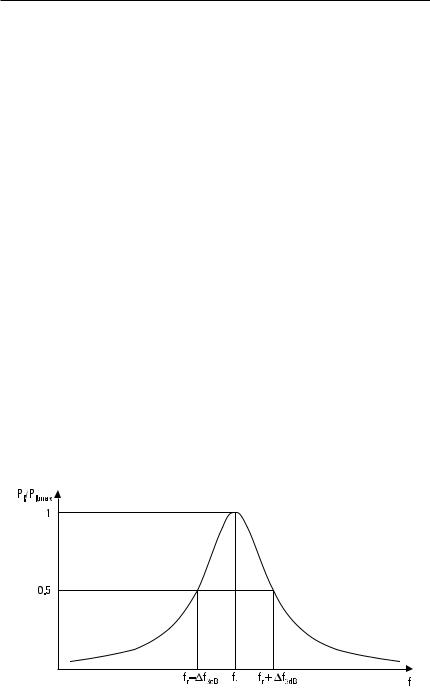
±Dv3dB = ±vr /(2Q ), the real and imaginary parts of the input impedance are equal, the magnitude of the admittance is √2G, and the phase of the admittance is ±p/4. Then the power loss in the resonator is half of that at the resonance frequency. Thus the quality factor may also be defined with the half-power frequencies illustrated in Figure 7.3 as
Q = |
vr |
= |
f r |
|
(7.6) |
2Dv3dB |
2Df 3dB |
||||
In other words, the quality factor of a resonator is a measure of its selectivity. The higher the quality factor, the narrower the frequency response of a resonator.
7.1.3 Coupled Resonator
A resonator may have one, two, or more couplings to the external circuit. Figure 7.4 shows the normalized equivalent circuits of resonators having one
Figure 7.3 Power absorbed in a resonator.

|
|
|
|
|
Resonators and Filters |
145 |
|||||||||
|
|
|
|
|
|
|
|
|
|
|
|
|
|
|
|
|
|
|
|
|
|
|
|
|
|
|
|
|
|
|
|
|
|
|
|
|
|
|
|
|
|
|
|
|
|
|
|
|
|
|
|
|
|
|
|
|
|
|
|
|
|
|
|
|
|
|
|
|
|
|
|
|
|
|
|
|
|
|
|
|
|
|
|
|
|
|
|
|
|
|
|
|
|
|
|
|
|
|
|
|
|
|
|
|
|
|
|
|
|
|
|
|
|
|
|
|
|
|
|
|
|
|
|
|
|
|
|
|
|
|
|
|
|
|
|
|
|
|
|
|
|
|
|
|
|
|
|
|
|
|
|
|
|
|
|
|
|
|
|
|
|
|
|
|
|
|
|
|
|
|
|
|
|
|
|
|
|
|
|
|
|
|
|
|
|
|
|
|
|
|
|
|
|
|
|
|
|
|
|
|
|
|
|
|
|
|
|
|
|
|
|
|
|
|
|
|
|
|
|
|
|
|
|
|
|
|
|
|
|
|
|
|
|
|
|
|
|
|
|
|
|
|
|
|
|
|
|
|
|
|
|
|
|
|
|
|
|
|
|
|
|
|
|
|
|
|
|
|
|
|
|
|
|
|
|
|
|
|
|
|
|
|
|
|
|
|
|
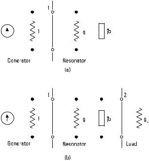
Figure 7.4 Equivalent circuits of resonators: (a) one coupling; and (b) two couplings.
and two couplings. A generator (current source) having a normalized output admittance of 1 is connected to port 1. The load admittance at port 2 of the resonator having two couplings is g L .
Let us consider at first the resonator with one coupling. The normalized input impedance is
y in = g + jb |
(7.7) |
The total conductance of the circuit is 1 + g , whereas that of the resonator alone is g . Therefore, the resonance curve such as that in Figure 7.3 has a peak that is broader by a factor of (1 + g )/g when the external coupling is taken into account.
The power loss in the circuit is divided into two parts, for each of which we can define a quality factor. The unloaded quality factor Q 0 is related to the loss in the resonator. Absorption in the metal walls and in the dielectric medium and radiation into free space are the sources of this loss. Q 0 can be obtained from those frequencies f r ± D f 0 at which g = b :

146 Radio Engineering for Wireless Communication and Sensor Applications
Q 0 |
= |
f r |
|
(7.8) |
||
2Df 0 |
||||||
|
|
|
||||
The external quality factor Q e is a measure of losses in the external |
||||||
circuit. From those frequencies f r ± D f e at which 1 = b, we get |
|
|||||
Q e |
= |
f r |
|
(7.9) |
||
2D f e |
||||||
|
|
|
||||
The loaded quality factor Q L describes the losses of the whole circuit. |
||||||
From frequencies f r ± D f L at which 1 + g = b, we get |
|
|||||
Q L |
= |
f r |
|
(7.10) |
||
2D f L |
||||||
|
|
|
||||
Because the power loss is inversely proportional to the corresponding quality factor, we can combine different loss components as
1 |
= |
1 |
|
+ |
1 |
(7.11) |
|
Q L |
Q 0 |
Q e |
|||||
|
|
|
|||||
or in other words, the total loss equals the sum of the loss in the resonator and the loss in the external circuit.
Figure 7.5 illustrates how the quality factors can be obtained from the input admittance yin ( f ) presented on the Smith chart. From the intersection
points of yin ( f ) with the lines b = g , b = 1, and b = 1 + g , we get the frequency deviations D f 0 , Df e , and Df L , from which we calculate Q 0 , Q e ,
and Q L using (7.8) through (7.10).
If Q e > Q 0 (1 < g ), the resonator loss at the resonance is larger than the loss in the external circuit; the resonator is undercoupled. For an overcoupled resonator, Q e < Q 0 (1 > g ), and the resonator loss at the resonance is smaller than the external loss. The coupling is called critical when Q e = Q 0 ; then the resonator is matched to the generator at resonance.
For a resonator having two couplings we can define two external quality factors: Q e1 for port 1 and Q e2 for port 2. The elements of the equivalent circuits can also be represented using the quality factors as g = Q e1 /Q 0 ,
g L = Q e1 /Q e2 , and b = gQ 0 2D f /f r = Q e1 2Df /f r . The transducer power loss of the resonator is
