
- •1. INTEGRATED AND AUTOMATED MANUFACTURING
- •1.1 INTRODUCTION
- •1.1.1 Why Integrate?
- •1.1.2 Why Automate?
- •1.2 THE BIG PICTURE
- •1.2.2 The Architecture of Integration
- •1.2.3 General Concepts
- •1.3 PRACTICE PROBLEMS
- •2. AN INTRODUCTION TO LINUX/UNIX
- •2.1 OVERVIEW
- •2.1.1 What is it?
- •2.1.2 A (Brief) History
- •2.1.3 Hardware required and supported
- •2.1.4 Applications and uses
- •2.1.5 Advantages and Disadvantages
- •2.1.6 Getting It
- •2.1.7 Distributions
- •2.1.8 Installing
- •2.2 USING LINUX
- •2.2.1 Some Terminology
- •2.2.2 File and directories
- •2.2.3 User accounts and root
- •2.2.4 Processes
- •2.3 NETWORKING
- •2.3.1 Security
- •2.4 INTERMEDIATE CONCEPTS
- •2.4.1 Shells
- •2.4.2 X-Windows
- •2.4.3 Configuring
- •2.4.4 Desktop Tools
- •2.5 LABORATORY - A LINUX SERVER
- •2.6 TUTORIAL - INSTALLING LINUX
- •2.7 TUTORIAL - USING LINUX
- •2.8 REFERENCES
- •3. AN INTRODUCTION TO C/C++ PROGRAMMING
- •3.1 INTRODUCTION
- •3.2 PROGRAM PARTS
- •3.3 CLASSES AND OVERLOADING
- •3.4 HOW A ‘C’ COMPILER WORKS
- •3.5 STRUCTURED ‘C’ CODE
- •3.6 COMPILING C PROGRAMS IN LINUX
- •3.6.1 Makefiles
- •3.7 ARCHITECTURE OF ‘C’ PROGRAMS (TOP-DOWN)
- •3.8 CREATING TOP DOWN PROGRAMS
- •3.9 CASE STUDY - THE BEAMCAD PROGRAM
- •3.9.1 Objectives:
- •3.9.2 Problem Definition:
- •3.9.3 User Interface:
- •3.9.3.1 - Screen Layout (also see figure):
- •3.9.3.2 - Input:
- •3.9.3.3 - Output:
- •3.9.3.4 - Help:
- •3.9.3.5 - Error Checking:
- •3.9.3.6 - Miscellaneous:
- •3.9.4 Flow Program:
- •3.9.5 Expand Program:
- •3.9.6 Testing and Debugging:
- •3.9.7 Documentation
- •3.9.7.1 - Users Manual:
- •3.9.7.2 - Programmers Manual:
- •3.9.8 Listing of BeamCAD Program.
- •3.10 PRACTICE PROBLEMS
- •3.11 LABORATORY - C PROGRAMMING
- •4. NETWORK COMMUNICATION
- •4.1 INTRODUCTION
- •4.2 NETWORKS
- •4.2.1 Topology
- •4.2.2 OSI Network Model
- •4.2.3 Networking Hardware
- •4.2.4 Control Network Issues
- •4.2.5 Ethernet
- •4.2.6 SLIP and PPP
- •4.3 INTERNET
- •4.3.1 Computer Addresses
- •4.3.2 Computer Ports
- •4.3.2.1 - Mail Transfer Protocols
- •4.3.2.2 - FTP - File Transfer Protocol
- •4.3.2.3 - HTTP - Hypertext Transfer Protocol
- •4.3.3 Security
- •4.3.3.1 - Firewalls and IP Masquerading
- •4.4 FORMATS
- •4.4.1 HTML
- •4.4.2 URLs
- •4.4.3 Encryption
- •4.4.4 Clients and Servers
- •4.4.5 Java
- •4.4.6 Javascript
- •4.5 NETWORKING IN LINUX
- •4.5.1 Network Programming in Linux
- •4.6 DESIGN CASES
- •4.7 SUMMARY
- •4.8 PRACTICE PROBLEMS
- •4.9 LABORATORY - NETWORKING
- •4.9.1 Prelab
- •4.9.2 Laboratory
- •5. DATABASES
- •5.1 SQL AND RELATIONAL DATABASES
- •5.2 DATABASE ISSUES
- •5.3 LABORATORY - SQL FOR DATABASE INTEGRATION
- •5.4 LABORATORY - USING C FOR DATABASE CALLS
- •6. COMMUNICATIONS
- •6.1 SERIAL COMMUNICATIONS
- •6.2 SERIAL COMMUNICATIONS UNDER LINUX
- •6.3 PARALLEL COMMUNICATIONS
- •6.4 LABORATORY - SERIAL INTERFACING AND PROGRAMMING
- •6.5 LABORATORY - STEPPER MOTOR CONTROLLER
- •7. PROGRAMMABLE LOGIC CONTROLLERS (PLCs)
- •7.1 BASIC LADDER LOGIC
- •7.2 WHAT DOES LADDER LOGIC DO?
- •7.2.1 Connecting A PLC To A Process
- •7.2.2 PLC Operation
- •7.3 LADDER LOGIC
- •7.3.1 Relay Terminology
- •7.3.2 Ladder Logic Inputs
- •7.3.3 Ladder Logic Outputs
- •7.4 LADDER DIAGRAMS
- •7.4.1 Ladder Logic Design
- •7.4.2 A More Complicated Example of Design
- •7.5 TIMERS/COUNTERS/LATCHES
- •7.6 LATCHES
- •7.7 TIMERS
- •7.8 COUNTERS
- •7.9 DESIGN AND SAFETY
- •7.9.1 FLOW CHARTS
- •7.10 SAFETY
- •7.10.1 Grounding
- •7.10.2 Programming/Wiring
- •7.10.3 PLC Safety Rules
- •7.10.4 Troubleshooting
- •7.11 DESIGN CASES
- •7.11.1 DEADMAN SWITCH
- •7.11.2 CONVEYOR
- •7.11.3 ACCEPT/REJECT SORTING
- •7.11.4 SHEAR PRESS
- •7.12 ADDRESSING
- •7.12.1 Data Files
- •7.12.1.1 - Inputs and Outputs
- •7.12.1.2 - User Numerical Memory
- •7.12.1.3 - Timer Counter Memory
- •7.12.1.4 - PLC Status Bits (for PLC-5s)
- •7.12.1.5 - User Function Memory
- •7.13 INSTRUCTION TYPES
- •7.13.1 Program Control Structures
- •7.13.2 Branching and Looping
- •7.13.2.1 - Immediate I/O Instructions
- •7.13.2.2 - Fault Detection and Interrupts
- •7.13.3 Basic Data Handling
- •7.13.3.1 - Move Functions
- •7.14 MATH FUNCTIONS
- •7.15 LOGICAL FUNCTIONS
- •7.15.1 Comparison of Values
- •7.16 BINARY FUNCTIONS
- •7.17 ADVANCED DATA HANDLING
- •7.17.1 Multiple Data Value Functions
- •7.17.2 Block Transfer Functions
- •7.18 COMPLEX FUNCTIONS
- •7.18.1 Shift Registers
- •7.18.2 Stacks
- •7.18.3 Sequencers
- •7.19 ASCII FUNCTIONS
- •7.20 DESIGN TECHNIQUES
- •7.20.1 State Diagrams
- •7.21 DESIGN CASES
- •7.21.1 If-Then
- •7.21.2 For-Next
- •7.21.3 Conveyor
- •7.22 IMPLEMENTATION
- •7.23 PLC WIRING
- •7.23.1 SWITCHED INPUTS AND OUTPUTS
- •7.23.1.1 - Input Modules
- •7.23.1.2 - Actuators
- •7.23.1.3 - Output Modules
- •7.24 THE PLC ENVIRONMENT
- •7.24.1 Electrical Wiring Diagrams
- •7.24.2 Wiring
- •7.24.3 Shielding and Grounding
- •7.24.4 PLC Environment
- •7.24.5 SPECIAL I/O MODULES
- •7.25 PRACTICE PROBLEMS
- •7.26 REFERENCES
- •7.27 LABORATORY - SERIAL INTERFACING TO A PLC
- •8. PLCS AND NETWORKING
- •8.1 OPEN NETWORK TYPES
- •8.1.1 Devicenet
- •8.1.2 CANbus
- •8.1.3 Controlnet
- •8.1.4 Profibus
- •8.2 PROPRIETARY NETWORKS
- •8.2.0.1 - Data Highway
- •8.3 PRACTICE PROBLEMS
- •8.4 LABORATORY - DEVICENET
- •8.5 TUTORIAL - SOFTPLC AND DEVICENET
- •9. INDUSTRIAL ROBOTICS
- •9.1 INTRODUCTION
- •9.1.1 Basic Terms
- •9.1.2 Positioning Concepts
- •9.1.2.1 - Accuracy and Repeatability
- •9.1.2.2 - Control Resolution
- •9.1.2.3 - Payload
- •9.2 ROBOT TYPES
- •9.2.1 Basic Robotic Systems
- •9.2.2 Types of Robots
- •9.2.2.1 - Robotic Arms
- •9.2.2.2 - Autonomous/Mobile Robots
- •9.2.2.2.1 - Automatic Guided Vehicles (AGVs)
- •9.3 MECHANISMS
- •9.4 ACTUATORS
- •9.5 A COMMERCIAL ROBOT
- •9.5.1 Mitsubishi RV-M1 Manipulator
- •9.5.2 Movemaster Programs
- •9.5.2.0.1 - Language Examples
- •9.5.3 Command Summary
- •9.6 PRACTICE PROBLEMS
- •9.7 LABORATORY - MITSUBISHI RV-M1 ROBOT
- •9.8 TUTORIAL - MITSUBISHI RV-M1
- •10. OTHER INDUSTRIAL ROBOTS
- •10.1 SEIKO RT 3000 MANIPULATOR
- •10.1.1 DARL Programs
- •10.1.1.1 - Language Examples
- •10.1.1.2 - Commands Summary
- •10.2 IBM 7535 MANIPULATOR
- •10.2.1 AML Programs
- •10.3 ASEA IRB-1000
- •10.4 UNIMATION PUMA (360, 550, 560 SERIES)
- •10.5 PRACTICE PROBLEMS
- •10.6 LABORATORY - SEIKO RT-3000 ROBOT
- •10.7 TUTORIAL - SEIKO RT-3000 ROBOT
- •10.8 LABORATORY - ASEA IRB-1000 ROBOT
- •10.9 TUTORIAL - ASEA IRB-1000 ROBOT
- •11. ROBOT APPLICATIONS
- •11.0.1 Overview
- •11.0.2 Spray Painting and Finishing
- •11.0.3 Welding
- •11.0.4 Assembly
- •11.0.5 Belt Based Material Transfer
- •11.1 END OF ARM TOOLING (EOAT)
- •11.1.1 EOAT Design
- •11.1.2 Gripper Mechanisms
- •11.1.2.1 - Vacuum grippers
- •11.1.3 Magnetic Grippers
- •11.1.3.1 - Adhesive Grippers
- •11.1.4 Expanding Grippers
- •11.1.5 Other Types Of Grippers
- •11.2 ADVANCED TOPICS
- •11.2.1 Simulation/Off-line Programming
- •11.3 INTERFACING
- •11.4 PRACTICE PROBLEMS
- •11.5 LABORATORY - ROBOT INTERFACING
- •11.6 LABORATORY - ROBOT WORKCELL INTEGRATION
- •12. SPATIAL KINEMATICS
- •12.1 BASICS
- •12.1.1 Degrees of Freedom
- •12.2 HOMOGENEOUS MATRICES
- •12.2.1 Denavit-Hartenberg Transformation (D-H)
- •12.2.2 Orientation
- •12.2.3 Inverse Kinematics
- •12.2.4 The Jacobian
- •12.3 SPATIAL DYNAMICS
- •12.3.1 Moments of Inertia About Arbitrary Axes
- •12.3.2 Euler’s Equations of Motion
- •12.3.3 Impulses and Momentum
- •12.3.3.1 - Linear Momentum
- •12.3.3.2 - Angular Momentum
- •12.4 DYNAMICS FOR KINEMATICS CHAINS
- •12.4.1 Euler-Lagrange
- •12.4.2 Newton-Euler
- •12.5 REFERENCES
- •12.6 PRACTICE PROBLEMS
- •13. MOTION CONTROL
- •13.1 KINEMATICS
- •13.1.1 Basic Terms
- •13.1.2 Kinematics
- •13.1.2.1 - Geometry Methods for Forward Kinematics
- •13.1.2.2 - Geometry Methods for Inverse Kinematics
- •13.1.3 Modeling the Robot
- •13.2 PATH PLANNING
- •13.2.1 Slew Motion
- •13.2.1.1 - Joint Interpolated Motion
- •13.2.1.2 - Straight-line motion
- •13.2.2 Computer Control of Robot Paths (Incremental Interpolation)
- •13.3 PRACTICE PROBLEMS
- •13.4 LABORATORY - AXIS AND MOTION CONTROL
- •14. CNC MACHINES
- •14.1 MACHINE AXES
- •14.2 NUMERICAL CONTROL (NC)
- •14.2.1 NC Tapes
- •14.2.2 Computer Numerical Control (CNC)
- •14.2.3 Direct/Distributed Numerical Control (DNC)
- •14.3 EXAMPLES OF EQUIPMENT
- •14.3.1 EMCO PC Turn 50
- •14.3.2 Light Machines Corp. proLIGHT Mill
- •14.4 PRACTICE PROBLEMS
- •14.5 TUTORIAL - EMCO MAIER PCTURN 50 LATHE (OLD)
- •14.6.1 LABORATORY - CNC MACHINING
- •15. CNC PROGRAMMING
- •15.1 G-CODES
- •15.3 PROPRIETARY NC CODES
- •15.4 GRAPHICAL PART PROGRAMMING
- •15.5 NC CUTTER PATHS
- •15.6 NC CONTROLLERS
- •15.7 PRACTICE PROBLEMS
- •15.8 LABORATORY - CNC INTEGRATION
- •16. DATA AQUISITION
- •16.1 INTRODUCTION
- •16.2 ANALOG INPUTS
- •16.3 ANALOG OUTPUTS
- •16.4 REAL-TIME PROCESSING
- •16.5 DISCRETE IO
- •16.6 COUNTERS AND TIMERS
- •16.7 ACCESSING DAQ CARDS FROM LINUX
- •16.8 SUMMARY
- •16.9 PRACTICE PROBLEMS
- •16.10 LABORATORY - INTERFACING TO A DAQ CARD
- •17. VISIONS SYSTEMS
- •17.1 OVERVIEW
- •17.2 APPLICATIONS
- •17.3 LIGHTING AND SCENE
- •17.4 CAMERAS
- •17.5 FRAME GRABBER
- •17.6 IMAGE PREPROCESSING
- •17.7 FILTERING
- •17.7.1 Thresholding
- •17.8 EDGE DETECTION
- •17.9 SEGMENTATION
- •17.9.1 Segment Mass Properties
- •17.10 RECOGNITION
- •17.10.1 Form Fitting
- •17.10.2 Decision Trees
- •17.11 PRACTICE PROBLEMS
- •17.12 TUTORIAL - LABVIEW BASED IMAQ VISION
- •17.13 LABORATORY - VISION SYSTEMS FOR INSPECTION
- •18. INTEGRATION ISSUES
- •18.1 CORPORATE STRUCTURES
- •18.2 CORPORATE COMMUNICATIONS
- •18.3 COMPUTER CONTROLLED BATCH PROCESSES
- •18.4 PRACTICE PROBLEMS
- •18.5 LABORATORY - WORKCELL INTEGRATION
- •19. MATERIAL HANDLING
- •19.1 INTRODUCTION
- •19.2 VIBRATORY FEEDERS
- •19.3 PRACTICE QUESTIONS
- •19.4 LABORATORY - MATERIAL HANDLING SYSTEM
- •19.4.1 System Assembly and Simple Controls
- •19.5 AN EXAMPLE OF AN FMS CELL
- •19.5.1 Overview
- •19.5.2 Workcell Specifications
- •19.5.3 Operation of The Cell
- •19.6 THE NEED FOR CONCURRENT PROCESSING
- •19.7 PRACTICE PROBLEMS
- •20. PETRI NETS
- •20.1 INTRODUCTION
- •20.2 A BRIEF OUTLINE OF PETRI NET THEORY
- •20.3 MORE REVIEW
- •20.4 USING THE SUBROUTINES
- •20.4.1 Basic Petri Net Simulation
- •20.4.2 Transitions With Inhibiting Inputs
- •20.4.3 An Exclusive OR Transition:
- •20.4.4 Colored Tokens
- •20.4.5 RELATIONAL NETS
- •20.5 C++ SOFTWARE
- •20.6 IMPLEMENTATION FOR A PLC
- •20.7 PRACTICE PROBLEMS
- •20.8 REFERENCES
- •21. PRODUCTION PLANNING AND CONTROL
- •21.1 OVERVIEW
- •21.2 SCHEDULING
- •21.2.1 Material Requirements Planning (MRP)
- •21.2.2 Capacity Planning
- •21.3 SHOP FLOOR CONTROL
- •21.3.1 Shop Floor Scheduling - Priority Scheduling
- •21.3.2 Shop Floor Monitoring
- •22. SIMULATION
- •22.1 MODEL BUILDING
- •22.2 ANALYSIS
- •22.3 DESIGN OF EXPERIMENTS
- •22.4 RUNNING THE SIMULATION
- •22.5 DECISION MAKING STRATEGY
- •23. PLANNING AND ANALYSIS
- •23.1 FACTORS TO CONSIDER
- •23.2 PROJECT COST ACCOUNTING
- •24. REFERENCES
- •25. APPENDIX A - PROJECTS
- •25.1 TOPIC SELECTION
- •25.1.1 Previous Project Topics
- •25.2 CURRENT PROJECT DESCRIPTIONS
- •26. APPENDIX B - COMMON REFERENCES
- •26.1 JIC ELECTRICAL SYMBOLS
- •26.2 NEMA ENCLOSURES
page 258
4. A controls network is to be 1500m long. Suggest three different types of networks that would meet the specifications.
(ans. Controlnet, Profibus, Ethernet with multiple subnets)
5 How many data bytes (maximum) could be transferred in one second with DH+?
(ans. the maximum transfer rate is 230 Kbps, with 11 bits per byte (1start+8data+2+stop) for 20909 bytes per second. Each memory write packet contains 17 overhead bytes, and as many as 2000 data bytes. Therefore as many as 20909*2000/(2000+17) = 20732 bytes could be transmitted per second. Note that this is ideal, the actual maximum rates would be actually be a fraction of this value.)
8.4 LABORATORY - DEVICENET
Purpose:
To be introduced to a software based PLC, interfacing with devices using devicenet and practical sensors.
Overview:
In previous coursework you have used PLC-5 processors. The software based PLC is very similar. The most noticeable difference is that Inputs and Outputs will appear in integer memory instead of the normal I:1 and O:0 blocks of memory.
The program to be developed for this laboratory should......
Pre-Lab:
1. Develop the ladder logic for the system described in the Overview.
In-Lab:
1.Follow the Softplc and Devicenet tutorial.
2.Implement a control system to .....
Submit (individually):
1. Program listings and prelab design work.
8.5 TUTORIAL - SOFTPLC AND DEVICENET
Objective: By the end of this tutorial you should be able to do the major steps required to connect a devicenet network and program a SoftPLC to control it. It will end with the connection and
page 259
programming of a Panelview 550 display.
1.Gather the components below. These will be used to build the Devicenet for the rest of the tutorial. When finding components the labels on the back are a good source of information. The information on the front of the devices is not normally useful.
-A PC with a PCIDS devicenet scanner card and software installed
-Devicenet Flex I/O rack on a din rail including,
24VDC adapter 1794-ADN Relay output 1794-DWB 24Vdc source input 1794-IV16 24Vdc sink input 1794-IB16
-a Sola 24Vdc power supply with a power cable attached
-a Sola 24Vdc power supply with a power tap (1485T-P2T5-T5) attached
-a devicenet capable photoswitch (42GNP-9000-QD)
-2 normal photoswitches (42GRP-9000-QD)
-4 Devicenet cable mini connector to wires (1485R-P3M5-C)
-a light stack with red/amber/green
-a central terminal Devicebox (1485P-P4T5-T5)
-3 network taps
-a stop pushbutton
-2 terminator resistors
-thick wire trunk line
-wires for connection
-Panelview 550 touch screen display
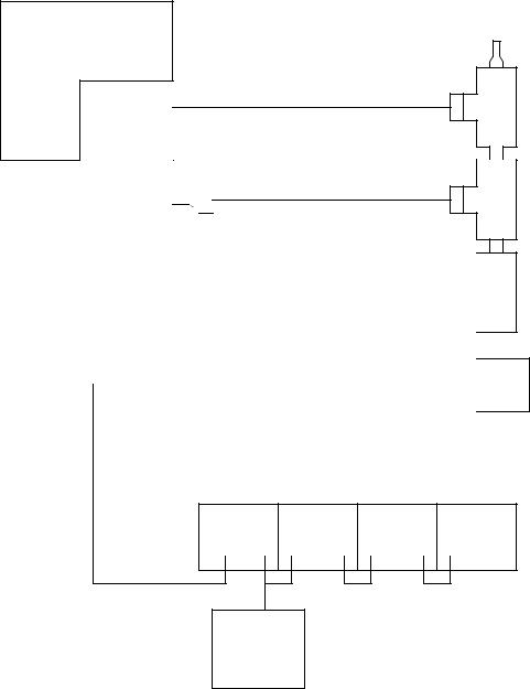
2.Wire up the network below (note: we will add more of the components later).

page 260
PC
1485R-P3R5-C
PCIDS
CARD
terminator 1485R-P3R5-C
|
|
|
|
|
|
|
|
|
|
|
24V sola |
|
|
|
|
|
|
|
|
|
|
power |
|
thick |
|
|
|
|
|
|
|
|
|
|
|
|
|
|
|
|
|||
supply |
|
line |
|
|
|
|
|
|
|
|
|
|
|
|
|
|
|
|
|
||
|
|
|
|
|
|
|
|
|
|
|
|
|
|
|
|
|
|
|
|
|
|
|
|
|
|
|
|
|
|
|
|
|
|
|
|
|
|
|
|
|
|
|
|
|
|
|
|
|
|
|
|
|
|
|
|
|
|
|
|
|
|
|
|
|
|
|
|
|
|
|
|
|
|
|
|
|
thick line
24Vdc sola power supply
terminator
tee
tee
tee
photosensor
flex I/O rack
3.Start the “RS Networx for Devicenet” software. When it starts it might show a diagram of previously programmed devices on the network. We need to get a current list of devices on the network. To do this pick “Selection” “Online”. This will scan the devices on the network and get their current configurations. After this the diagram on the screen will be current.
4.Next, we want to map the data from each of the Devicenet nodes to a location in the SoftPLC memory. Double click on the PCIDS card on the screen. Click on the “scanlist” tab (you may have to upload parameters). Make sure that all of the devices appear on the scanlist. Use the “Input” and “Output” tabs to map these devices to specific input and output memory. Notice
page 261
that this is organized in words (16bits). You will want to make a note of these values, because you will use these when programming the PLC. When done select “Apply” and then “OK”. Exit the program and save the changes. At this point a file has been set up that tells the SoftPLC what devices are on the Devicenet, and what to do with them.
5.Move the pointer to the bottom right of the screen. You will see a black dot near the time. Click twice on this (Note: when the SoftPLC is running this will be green). A screen entitled “Softlogix 5 Status Monitor” will popup. Click on “Config” and then “Start SoftLogix 5”. The SoftPLC should now be running. Click “OK” to dismiss the screens.
6.Start the “RS-Logix SL5 English” software (Note the ‘SL’). Start a “New Project”, the programming window should appear. You should now be ready to tell the SoftPLC that you will be using devicenet. Double click on “Processor Status” and on the pop-up window scroll across and select the “Dnet” tab. For the output file enter “9”, for the input file enter “10”, for the diagnostic file enter “11”. Dismiss the window and look at the memory locations under data files, there should now be I/O words there under N9, N10, N11. The input and output memory set in the RSNetworx program will be put in this memory.
7.Write a simple ladder logic program to read to smart optical sensor and output a value to the relay card. If you need help finding which inputs are which, try running a simple or empty program, and watching the memory.
8.Connect the other photooptical sensors and the light stack to the Flex I/O rack and write a more sophistocated program.
9.Connect the PanelView display, and reconfigure the devicenet network. Use the Panel Builder software to create a visual interface, and then download it to the touchscreen. Write ladder logic that uses it for input and output.