

page 240
8. PLCS AND NETWORKING
Computer |
|
Devicenet |
|
|
|
|
|
|
|
|
|
|
|
|
|
|
|
|
|
RS-232 |
Process |
|
|
|
|
|
Process |
|
|
|
|
Actuators |
|
|
|
|
|
Sensors |
|
|
|
|
|
Process |
||||
|
|
|
|
|
|
|
|
|
|
|
|
|
|
|
|||||
|
|
|
|
|
|
|
|
|
|
|
|
|
Process |
|
|
|
|
|
Process |
|
|
|
|
|
|
|
|
||
|
|
|
|
|
|
|
|
||
|
|
|
|
|
|
||||
|
|
|
Actuators |
|
|
|
|
|
Sensors |
|
|
|
|||||||
PLC
Normal I/O on PLC
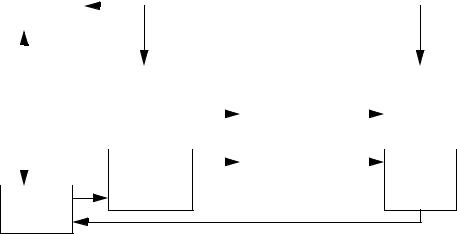
Figure 22.1 - A Communication Example
8.1 OPEN NETWORK TYPES
8.1.1 Devicenet
Devicenet has become one of the most widely supported control networks. It is an open standard, so components from a variety of manufacturers can be used together in the same control system. It is supported and promoted by the Open Devicenet Vendors Association (ODVA) (see http:/ /www.odva.org). This group includes members from all of the major controls manufacturers.
This network has been designed to be noise resistant and robust. One major change for the control engineer is that the PLC chassis can be eliminated and the network can be connected directly to the sensors and actuators. This will reduce the total amount of wiring by moving I/O points closer to the application point. This can also simplify the connection of complex devices,
page 241
such as HMIs. Two way communications inputs and outputs allow diagnosis of network problems from the main controller.
Devicenet covers all seven layers of the OSI standard. The protocol has a limited number of network address, with very small data packets. But this also helps limit network traffic and ensure responsiveness. The length of the network cables will limit the maximum speed of the network.
The basic features of are listed below.
•A single bus cable that delivers data and power.
•Up to 64 nodes on the network.
•Data packet size of 0-8 bytes.
•Lengths of 500m/250m/100m for speeds of 125kbps/250kbps/500kbps respectively.
•Devices can be added/removed while power is on.
•Based on the CANbus (Controller Area Network) protocol for OSI levels 1 and 2.
•Addressing includes peer-to-peer, multicast, master/slave, polling or change of state.
An example of a Devicenet network is shown in Figure 22.16. The dark black lines are the network cable. Terminators are required at the ends of the network cable to reduce electrical noise. In this case the PC would probably be running some sort of software based PLC program. The computer would have a card that can communicate with Devicenet devices. The ’FlexIO rack’ is a miniature rack that can hold various types of input and output modules. Power taps (or tees) split the signal to small side branches. In this case one of the taps connects a power supply, to provide the 24Vdc supply to the network. Another two taps are used to connect a ’smart sensor’ and another ’FlexIO rack’. The ’Smart sensor’ uses power from the network, and contains enough logic so that it is one node on the network. The network uses ’thin trunk line’ and ’thick trunk line’ which may limit network performance.
page 242
terminator
|
thin |
|
|
thin |
|
|
|
|
|
|
thick trunk line |
|
||||||
|
trunk tap |
|
|
trunk |
|
|
|
|
|
|
|
|||||||
|
|
|
power tap |
|
||||||||||||||
|
line |
|
|
|
|
|
line |
|
|
|
|
|
|
|
|
|
|
|
|
|
|
|
|
|
|
|
|
|
|
|
|
|
|
||||
|
|
|
|
|
|
|
|
|
|
|
|
|
|
|
|
|
|
|
|
|
|
|
|
|
|
|
|
|
|
|
|
|
|
|
|
|
|
|
|
|
|
|
drop |
|
|
|
|
|
|
|
|
|
||||
|
|
|
|
|
|
|
|
|
|
|
FlexIO |
|
|
|||||
|
|
|
|
|
line |
|
|
|
|
|
|
|
PC |
|||||
|
|
|
|
|
|
|
|
|
|
|
rack |
|
||||||
|
|
|
|
|
|
|
|
|
|
|
|
|
|
|
|
|
||
|
|
|
|
|
|
|
|
|
|
|
|
|
|
|
|
|
|
|
|
tap |
|
|
|
|
|
drop |
|
|
|
|
|
|
|
|
|
||
|
|
|
|
|
|
|
|
|
|
|
|
|
|
|
|
|
||
|
|
|
|
|
|
|
|
|
|
|
|
|
|
|
||||
|
|
|
|
|
|
|
|
line |
|
|
|
|
|
|
|
|
|
|
|
|
|
|
|
|
|
|
|
|
|
|
|
|
|
|
|||
|
|
|
|
|
|
|
|
|
|
|
|
|
|
|
|
|
|
|
|
Smart |
|
|
FlexIO |
|
|
|
power |
|
|
|
|
||||||
|
|
|
rack |
|
|
|
supply |
|
|
|
|
|||||||
|
sensor |
|
|
|
|
|
|
|
|
|
||||||||
|
|
|
|
|
|
|
|
|
|
|
|
|
|
|
||||
|
|
|
|
|
|
|
|
|
|
|
|
|
|
|
|
|
|
|
Figure 22.16 - A Devicenet Network
terminator
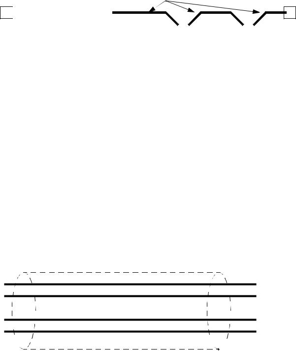
The network cable is important for delivering power and data. Figure 22.17 shows a basic
cable with two wires for data and two wires for the power. The cable is also shielded to reduce the
effects of electrical noise. The two basic types are thick and thin trunk line. The cables may come
with a variety of connections to devices.
•bare wires
•unsealed screw connector
•sealed mini connector
•sealed micro connector
•vampire taps
power (24Vdc)
data
 drain/shield
Thick trunk - carries up to 8A for power up to 500m
Thin trunk - up to 3A for power up to 100m
Figure 22.17 - Shielded Network Cable
page 243
Some of the design issues for this network include;
•Power supplies are directly connected to the network power lines.
•Length to speed is 156m/78m/39m to 125Kbps/250Kbps/500Kbps respectively.
•A single drop is limited to 6m.
•Each node on the network will have its own address between 0 and 63.
If a PLC-5 was to be connected to Devicenet a scanner card would need to be placed in the rack. The ladder logic in Figure 22.18 would communicate with the sensors through a scanner card in slot 3. The read and write blocks would read and write the Devicenet input values to integer memory from ’N7:40’ to ’N7:59’. The outputs would be copied from the integer memory between ’N7:20’ to ’N7:39’. The ladder logic to process inputs and outputs would need to examine and set bits in integer memory.

page 244
MG9:0/EN |
|
|
MSG |
|
|
(EN) |
||
|
|
|
|
|
Send/Rec Message |
|
|
|
|
|
|
|
|
|
|||
|
|
|
|
|
|
|
|
|
|
|
|
|
|
|
|
|
|
|
|
|
|
|
|
(DN) |
||
|
|
|
|
|
Control Block MG9:0 |
|
|
(ER) |
MG9:1/EN |
|
|
|
|
|
|||
|
|
|
|
|
||||
|
|
MSG |
|
|
(EN) |
|||
|
|
|
|
|
Send/Rec Message |
|
|
|
|
|
|
|
|
|
|
|
|
|
|
|
|
|
|
|
|
|
|
|
|
|
|
|
(DN) |
||
|
|
|
|
|
Control Block MG9:1 |
|
|
(ER) |
|
|
|
|
|
|
|
||
|
|
|
|
|
|
|
|
|
|
|
MG9:0 |
|
|
MG9:1 |
|
|
|
|
|
|
|
|
|
|||
Read/Write |
Write |
|
Read/Write |
|
Read |
|||
Data Table |
N7:20 |
|
Data Table |
|
N7:40 |
|||
Size |
20 |
|
Size |
20 |
||||
Local/Remote |
Remote |
|
Local/Remote |
|
Remote |
|||
Remote Station |
?? |
|
Remote Station |
?? |
||||
Link ID |
?? |
|
Link ID |
?? |
||||
Remote Link type |
?? |
|
Remote Link type |
?? |
||||
Local Node Addr. |
N/A |
|
Local Node Addr. |
|
N/A |
|||
Processor Type |
???? |
|
Processor Type |
???? |
||||
Dest. Addr. |
???? |
|
Dest. Addr. |
???? |
||||
Note: Get exact settings for these parametersXXXXXXXXXXXXXXXXX
Figure 22.18 - Communicating with Devicenet Inputs and Outputs
On an Allen Bradley Softlogix PLC the I/O will be copied into blocks of integer memory.
These blocks are selected by the user in setup software. The ladder logic would then using integer
memory for inputs and outputs, as shown in Figure 22.19. Here the inputs are copied into N9 inte-
ger memory, and the outputs are set by copying the N10 block of memory back to the outputs.