

page 198
7.18 COMPLEX FUNCTIONS
7.18.1 Shift Registers
• The values can be shifted left or right with the following functions.
BSL - shifts left from the LSB to the MSB. The LSB must be supplied
BSR - similar to the BSL, except the bit is input to the MSB and shifted to the LSB
•These use bit memory blocks of variable length.
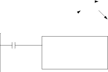
•An example of a shift register is given below. In this case it is taking the value of bit B3:1/0 and putting it in the control word bit R6:2/UL. It then shifts the bits once to the right, B3:1/0 = B3:1/1 then B3:1/1 = B3:1/2 then B3:1/2 = B3:1/3 then B3:1/3 = B3:1/4. Then the input bit is put into the most significant bit B3:1/4 = I:000/00.
|
|
|
|
|
|
|
|
|
|
|
|
|
|
|
bits shift right |
|||||
B3:1 |
|
|
|
|
|
|
|
|
|
|
|
|
|
|
|
|
|
|
|
|
MSB |
|
|
|
|
|
|
|
|
|
|
|
|
|
|
|
|
|
|
LSB |
|
0 |
0 |
0 |
0 |
0 |
0 |
0 |
0 |
0 |
0 |
0 |
0 |
0 |
0 |
0 |
0 |
|||||
|
15 |
|
|
|
|
|
|
|
|
|
|
|
|
|
|
|
|
|
|
00 |
|
|
|
|
|
|
|
|
|
|
|
|
|
|
|
|
|
|
|
||
|
|
|
|
|
|
|
|
I:000/00 |
|
|
|
|
|
R6:2/UL |
||||||
|
|
|
|
|
|
|
|
|
|
|
|
|
||||||||
|
|
|
|
|
|
|
|
5 |
|
|
|
|||||||||
BSR
File B3:1
Control R6:2
Bit address I:000/00
Length 5
• There are other types of shift registers not implemented in PLC-5s.
page 199
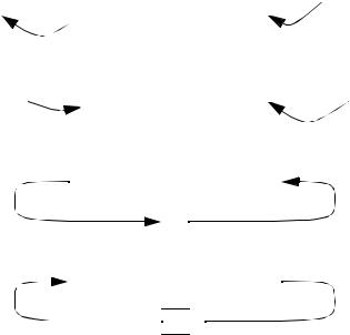
Arithmetic Shift Left (ASL) |
|
|
|
|
|
|
|
|
|
|
|
|
|
||||
|
carry |
msb |
|
|
|
|
|
|
|
|
lsb |
|
|
|
|||
|
0 |
|
0 |
|
0 |
0 |
0 |
0 |
0 |
0 |
0 |
|
0 |
|
|
||
|
|
|
|
|
|
|
|||||||||||
Arithmetic Shift Right (ASR) |
|
|
|
|
|
|
|
|
|
|
|
carry |
|||||
0 |
|
|
|
|
|
|
|
|
|
|
|
|
|
||||
0 |
|
0 |
0 |
0 |
0 |
0 |
0 |
0 |
|
||||||||
|
|
|
0 |
|
|||||||||||||
Rotate Left (ROL) |
|
|
|
|
|
|
|
|
|
|
|
|
|
|
|||
|
|
|
|
|
|
|
|
|
|
|
|
|
|
|
|||
0 |
|
0 |
0 |
0 |
0 |
0 |
0 |
0 |
|
|
|
|
|||||
|
|
|
|
|
|
|
|
||||||||||
|
|
|
|
|
|
|
|
carry |
|
|
|
|
|
|
|
||
|
|
|
|
|
|
|
|
|
0 |
|
|
|
|
|
|
|
|
Rotate Right (ROR) |
|
|
|
|
|
|
|
|
|
|
|
|
|
|
|
||
0 |
|
0 |
0 |
0 |
0 |
0 |
0 |
0 |
|
|
|
|
|||||
|
|
|
|
|
|
|
|
||||||||||
carry 
 0
0 
7.18.2 Stacks
•We can also use stack type commands. These allow values to be stored in a ‘pile’. This allows us to write programs that will accumulate values that can be used later, or in sequence.
•The basic concept of a FIFO stack is that the first element in is the first element out.
•The PLC-5 commands are FFL to load the stack, and FFU to unload it.
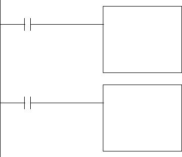
•The example below shows two instructions to load and unload the stack. The first time FFL is activated it will grab all of the bits from the input card I:001 and store them on the stack, at N7:0. The next value would be at N7:1, and so on until the stack length is met. When FFU is used the value at N7:0 will be moved to set all of the bits on the output card O:003 and the values on
page 200
the stack will be shifted up so that the value previously in N7:1 is now in N7:0, etc. (note: the
source and destination do not need to be inputs and outputs)
A
FFL
source I:001 FIFO N7:0 Control R6:0 length 5 position 0
B
FFU
FIFO N7:0 destination O:003 Control R6:0 length 5
position 0
• A Last-In-First-Out stack can also be used with the LFL/LFU functions.
7.18.3 Sequencers
•Basically, sequencers are a method for using predetermined patterns to drive a process
•These were originally based on motor driven rotating cams that made and broke switches. When a number of these cams were put together, they would be equivalent to a binary number, and could control multiple system variables.
page 201
As it rotates it makes contact with none, one, or two terminals, as determined by the depressions and rises in the rotating cam.
•A sequencer can keep a set of values in memory and move these to memory locations (such as an output card) when directed.
•These are well suited to state diagrams/processes with a single flow of execution (like traffic lights)
•The commands are,
SQO(start,mask,source,destination,control,length) - sequencer output from table to memory address
SQI(start,mask,source,control,length) - sequencer input from memory address to table
SQL(start,source,control,length) - sequencer load to set up the sequencer parameters
• An example of a sequencer is given below for traffic light control. The light patterns are stored in memory (entered manually by the programmer). These are then moved out to the output card as the function is activated. The mask (003F = 0000000000111111) is used so that only the 6 LSB are changed.