


page 147
7.3.3 Ladder Logic Outputs
•The outputs allow switches to close that supply or cut-off power to control devices.
•Ladder logic indicates what to do with the output, regardless of what is hooked up -- The programmer and electrician that connect the PLC are responsible for that.
•Outputs can go to electrical outputs, or to memory.
•Output symbols -
When power is applied (on) the output is activated
When power is not applied (off) the output is activated
•We can relate these to actual outputs using numbers (look for these on the front of the PLC).
•For the Micrologix PLCs the outputs are labelled ‘O:0.0/x’ where x is the output number 0
to 5.
7.4 LADDER DIAGRAMS
•These diagrams are read from left to right, top to bottom.
•For the ladder logic below the sequence of operations would be B1, B2 on the top first, then

page 148
the bottom. This would be followed by T1, then F1.
B1 |
B2 |
|
|
T1 |
|||
|
|
|
|
|
F1 |
||
|
|
|
|
|
|
|
|
|
|
|
|
|
|
|
|
|
|
|
|
|
|
|
|
B1 |
B2 |
|
|
|
|
|
|
|
|
|
|
|
|
|
|
|
|
|
|
|
|
|
|
|
|
|
|
|
|
|
|
• Power flow can be used to consider how ladder diagrams work. Power must be able to flow from the left to the right.
7.4.1 Ladder Logic Design
eg. Burglar Alarm
1.If alarm is on, check sensors.
2.If window/door sensor is broken (turns off), sound alarm and turn on lights.
3.If motion sensor goes on (detects thief), sound alarm and turn on lights.
A = Alarm and lights switch (1 = on)
W = Window/Door sensor (1 = OK)
M = Motion Sensor (0 = OK)
S = Alarm Active switch (1 = on)
page 149
We can do this with ladder logic |
|
||||||||
|
|
|
M |
|
|
S |
A |
||
|
|||||||||
|
|
|
|
|
|
|
|
|
|
|
|
|
|
|
|
|
|
|
|
|
|
|
|
|
|
|
|
|
|
|
|
|
W |
S |
|
|
|||
|
|
|
|
|
|
|
|
|
|
|
|
|
|
|
|
|
|
|
|
|
|
|
|
|
|
|
|
|
|
|
|
|
|
|
|
|
|
|
|
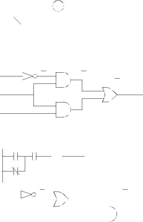
We can also draw an electronic circuit for this -
W |
W |
(S*W) |
|
|
(S*W)+(S*M) |
S |
|
|
A
M
(S*M)
We can also simplify both the circuit and the ladder -
M S  A
A
W
W |
|
|
W |
|
|
|
S * (M+W) |
|||||||
|
|
(M+W) |
|
|||||||||||
|
|
|
|
|
|
|
|
|
= |
|
|
|||
M |
|
|
|
|
|
|
|
|
(S*W)+(S*M) |
|||||
|
|
|
|
|
|
|
|
|||||||
S |
|
|
|
|
|
|
|
|
|
|
|
|
|
A |
|
|
|
|
|
|
|
|
|
|
|
|
|
||
|
|
|
|
|
|
|
|
|
|
|
|
|
||
|
|
|
|
|
|
|
|
|
|
|
|
|
||
|
|
|
|
|
|
|
|
|
|
|
|
|
|
|

page 150
7.4.2 A More Complicated Example of Design
D
E
C
A
F
B
|
|
|
|
|
|
|
|
|
|
The gates can be purchased for |
D |
|
C |
|
B |
|
about $0.25 each in bulk. |
||||
|
|
A |
Inputs and outputs are |
|||||||
|
|
|
|
|
|
|
|
|
||
|
|
|
|
|
|
|
|
|
|
|
|
E |
|
|
|
|
|
|
|
|
typically 5V. |
|
|
|
|
|
|
An inexpensive PLC is worth |
||||
|
|
|
|
|
||||||
|
|
|
|
|
|
|
||||
|
|
|
|
|
|
|||||
|
C |
|
|
|
|
|
at least a few hundred dollars. |
|||
|
|
|
|
|
||||||
|
|
|
|
|
|
|
|
|
Consider the cost trade-off! |
|
|
|
|
|
|
|
|
|
|||
|
|
|
|
|
|
|
|
|
|
|
|
|
|
|
|
|
|
|
|
|
|
F |
|
C |
|
|
|
|
|
|||
|
|
|
|
|
|
|
|
|
|
Why are gates not used more often? |
|
|
|
|
|
|
|
|
|
|
|
D |
|
E |
A |
F |
|
C |
|
B |
|
D |
|
C |
|
B |
A |
Simplified |
|
|
|
|
|
|
|
|
|
|
|
|
|
|
|
|
|
|
|
|
|
|
|
|
|
E
F