

page 141
outputs after the ladder logic program is done. This continues indefinitely while the PLC is run-
ning.
• PLC operation can be shown with a time-line -
|
Self |
input |
logic |
output |
|
Self |
input |
logic |
output |
Self |
input |
logic |
|
|
test |
scan |
solve |
scan |
|
test |
scan |
solve |
scan |
test |
scan |
solve |
|
|
|
|
|
|
|
|
|
|
|
|
|
|
|
|
|
|
|
|
|
|
|
|
|
|
|||
|
|
|
|
|
|
|
|
|
|
|
|
|
|
|
0 |
PLC turns on |
|
|
ranges from 1 to 100 ms |
|
|
|
time |
||||
|
|
|
|
|
|||||||||
|
|
|
|
|
|
|
|
|
|
|
|
||
SELF TEST - Checks to see if all cards error free, resets watch-dog timer, etc. (A watchdog timer will cause an error, and shut down the PLC if not reset within a short period of time - this would indicate that the ladder logic is not being scanned normally).
INPUT SCAN - Reads input values from the chips in the input cards and copies their values to memory. This makes the PLC operation faster and avoids cases where an input changes from the start to the end of the program (e.g., an emergency stop). There are special PLC functions that read the inputs directly and avoid the input tables.
LOGIC SOLVE/SCAN - Based on the input table in memory, the program is executed one step at a time, and outputs are updated. This is the focus of the later sections.
OUTPUT SCAN - The output table is copied from memory to the output chips. These chips then drive the output devices.
7.3 LADDER LOGIC
•Ladder logic has been developed to mimic relay logic - to make the computer more acceptable to companies and employees.
•Original efforts resisted the use of computers because they required new skills and approaches, but the use of ladder logic allowed a much smaller paradigm shift.
page 142
• Original relay ladder logic diagrams show how to hook-up inputs to run outputs.
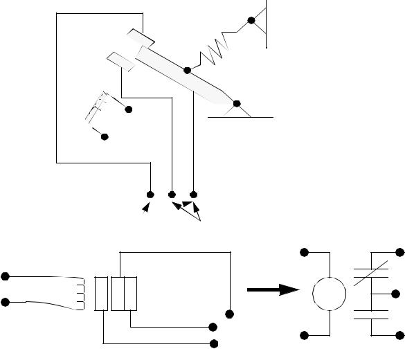
Relay - An input coil uses a voltage/current to create a magnetic field. As the coil becomes magnetic it pulls a metal switch (or reed) towards it and makes an electrical contact. The contact that closes when the coil is energized is normally open. There is a contact that the reed touches without the coil energized is called the normally closed contact. Relays are used to let one power source close a switch for another (often high current) power source while keeping them isolated.
 input coil
normally |
normally |
closed |
open |
Schematic - The drawing below shows the relay above in a symbolic form.
OR
page 143
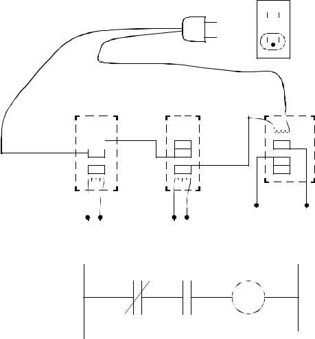
A Circuit - A mix of inputs and outputs allows logical selection of a device.
115VAC  wall plug
relay logic
output
(normally open)
input
(normally closed) input
(normally open)
ladder logic
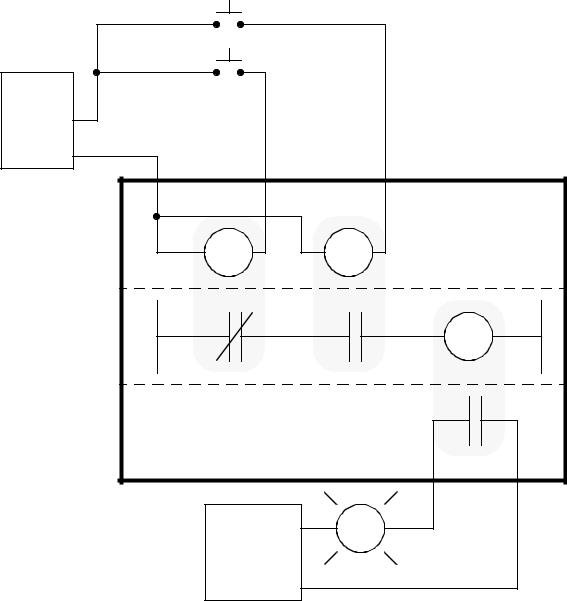
• We can then imaging this in context of a PLC. (this idea was suggested by Walt Siedelman
of Ackerman Electric)
page 144
push buttons
power |
supply |
+24V |
com. |
PLC |
inputs |
ladder |
logic |
outputs |
115Vac |
AC power |
neut. |
7.3.1 Relay Terminology |
• Contactor - special relays for switching of large loads.
page 145
•Motor Starter - Basically a contactor in series with an overload relay to cut off when too much current is drawn.
•Rated Voltage - Suggested operation voltage. Lower levels can result in failure to operate: voltages above shorten life.
•Rated Current - The maximum current before contact damage occurs (welding or melting).
•DC relays require special arc suppression. AC relays have a zero crossing to reduce relay arc problems.
•AC relays require a shading pole to maintain contact. If a DC relay is used with AC power on the coil, it clicks on-and-off at the frequency of the AC (also known as chattering).